

Page 1

AGCO
ALLIS
O
PERATOR
16 HP Hydro
Mfg. No. 1692375
’
S
M
42” Mower Deck
Mfg. No. 1691662 Mfg. No. 1691663
ANUAL
48” Mower Deck
Page 2

500 N. Spring Street, P.O. Box 997
Port Washington,
WI 53074.0997
17143w01
Printed In USA
01995 Revised
Z/95
Page 3

O
PERATOR
’
S
M
ANUAL
16 HP Hydro
Mfg. No.
1692375
FC S
42” Mower Deck
Mfg. No. 1691662 Mfg. No. 1691663
ERIES
48” Mower Deck
Page 4

500 N. Spring Street, P.O. Box 997
Port Washington, WI
53074.0997
1714295-01
Printed In USA
01995 Revised
2195
Page 5

Table Of Contents
&
RIDER
SAFETY RULES.
DECALS..
FEATURES
Controls
Engine
Safety Interlock System
OPERATION
General.. ..............................................................................
Mower Installation.. .............................................................
Mower Removal
Operating The Mower.. .......................................................
Checks Before Starting.......................................................
Clutch/Brake Pedal
Starting The Engine
Selecting Ground Speed
Stopping The Rider
Pushing the Rider by
MOWING
MOWER
......................................................................
...............................................................................
.................................................................................
PATTERN
IDENTIFICATION..
...........................................................
&
CONTROLS..
..................................................................
.................................................................. 10
Operation
............................................................
.............................................................
Hand ................................................
&TIPS..
........................................
........................................................
...........................................
&
Engine Speed
....................................
.........................
.........................
.2
TROUBLESHOOTING & REPAIR
.5
.6
12
12
.I2
12
12
13
14
.15
3
.6
.7
6
9
.9
.9
General..
Troubleshooting The Rider.. ..............................................
Troubleshooting The
Checking the Battery
Charging A Completely
Jump Starting with
Auxiliary (Booster) Battery..
ADJUSTMENTS .........................................................
Seat Adjustment ................................................................
Neutral Adjustment..
Clutch/Brake Adjustment
PTO (Electric Clutch) Adjustment.. ....................................
Mower Adjustments...........................................................
BELT REPLACEMENT.. .............................................
Mower Belt.. .......................................................................
Power Unit Belt.. .................................................................
............................................................................
Discharged Battery.
Leveling the Mower ........................................................
Blade Brake Check..
...............................
Mower.. .............................................
..........................................................
.........................................................
.............................................
...........................................................
..................................................
........................................................
22
.22
.22
23
23
23
24
.26
.26
26
.27
.27
.27
.27
28
.29
.29
30
NORMAL CARE
Schedule .............................................................................
Checking/Adding Gasoline ................................................
Checking Tire Pressure
Lubrication ..........................................................................
Battery Maintenance
Checking Battery Fluid.....................................................
Cleaning the Battery and Cables
Check Transmission Fluid Level
Servicing the Mower
STORAGE
Temporary Storage.............................................................
Long Term Storage .............................................................
Starting After Storage..
..........................................................
......................................................
...........................................................
.....................................
.........................................
Blades..
...................................................................
............................................
.......................................................
16
16
.16
16
16
18
18
18
.19
20
SPECIFICATIONS ......................................................
PARTS&ACCESSORIES .........................................
Common Replacement Parts. .............................................
Maintenance Items ............................................................
Optional Accessories.
Technical Literature ............................................................
19
INTERNATIONAL SYMBOLS ....................................
NOTE: In this manual, “left” and “right” are referred to as seen
fmm the operating position.
20
29
21
.........................................................
.32
.33
33
.33
34
34
.35
1
Page 6
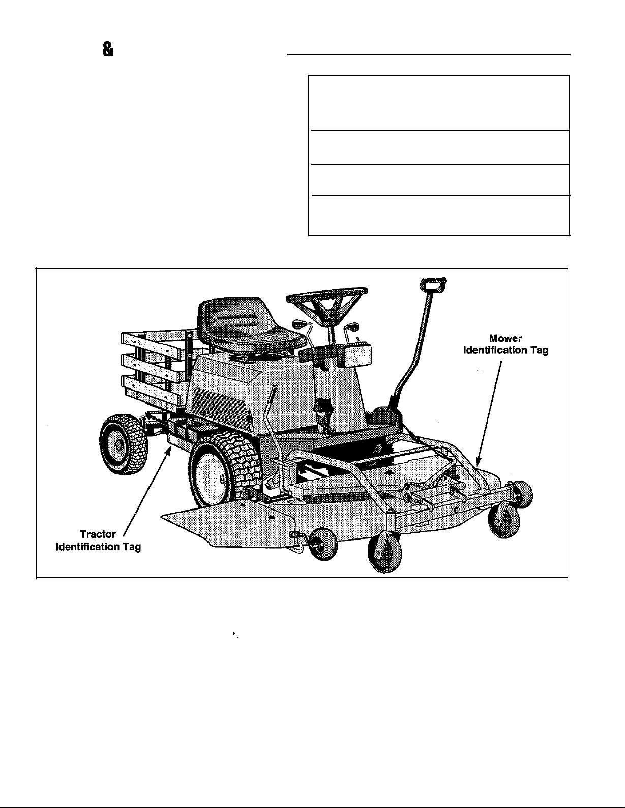
Tractor & Mower Identification
Record your model number, manufacturer number and
engine serial number in the space provided for easy reference.
The models and manufacturer numbers covered in this
manual are listed on the front cover.
The tractor I.D. tag is located on the right-side, below the
fuel tank, as shown below. The mower deck I.D. tag is on
the left side, top of the mower deck.
Refer to the engine Owner’s Manual for location of
engine serial number.
Be sure to fill out and return the Warranty Registration
Card supplied with your tractor.
Model Number:
Manufacturer Number:
Engine I.D. Number:
Dealer Name/Date Purchased:
MODEL REFERENCE
*.
2
Page 7

-
Safety Rules
Read these safety rules and follow them closely. Failure to obey these rules could result in loss of control of
rider, severe personal injury or death to you, or bystanders, or damage to property or equipment.
k is caoable of
signifies important cautions or warnings which must be followed.
-tina
hands and feet and throwina obiects. The triangle
a
Ihis
in text
GENERAL OPERATION
*
Read, understand, and follow all instructions in the
manual and on the unit before starting.
*
Only allow responsible adults, who are familiar with
the instructions, to operate the unit.
*
Clear the area of objects such as rocks, toys, wire,
etc., which could be picked up and thrown by the
blade(s).
l
Be sure the area is clear of other people before mow-
ing. Stop unit if anyone enters the area.
*
Never carry passengers.
*
Do not mow in reverse unless absolutely necessary.
Always look down and behind before and while trav-
elling
in reverse.
*
Be aware of the mower discharge direction and do
not point it at anyone. Do not operate the mower
without either the entire grass catcher or the deflector
in place.
*
Slow down before turning.
. Never leave a running unit unattended. Always
disengage the PTO, set parking brake, stop engine,
and remove keys before dismounting.
. Turn off the PTO switch to disengage the blades
when not mowing.
*
Stop engine before removing grass catcher or
unclogging chute.
*
Mow only in daylight or good artificial light.
*
Do not operate the unit while under the influence of
alcohol or drugs.
*
Watch for traffic when operating near or crossing
roadways.
*
Use extra care when loading or unloading the unit
into a trailer or truck.
SLOPE OPERATION
Slopes are a major factor related to loss-of-control and
tip-over accidents, which can result in severe injury or
I,
death. All slopes require extra caution. If you cannot
back up the slope or if you feel uneasy on it, do not mow it.
Do
Do Not
A
WARNING - SLOPE OPERATION
Never operate on slopes greater than 30 percent
(16.7’) which is a rise of three feet vertically in 10 feet
horizontally. Select slow ground speed before driving
onto slope. Use extra caution when operating on
slo es with rear-mounted grass catcher. Mow UP and
D&N
the slope never across the face use caution
when changing directions and DO NOT START OR
STOP ON SLOPE.
*
Mow up and down slopes, not across.
*
Remove obstacles such as rocks, tree limbs, etc.
*
Watch for holes, ruts, or bumps. Uneven terrain could
overturn the unit. Tall grass can hide obstacles.
*
Use slow speed.
*
Use extra care with grass catchers or other attach-
ments. These can change the stability of the unit.
*
Keep all movement on the slopes slow and gradual.
Do not make sudden changes in speed or direction.
*
Do not start or stop on a slope. If tires lose traction,
disengage the blade(s) and proceed slowly straight
down the slope.
*
Do notturn on slopes unless necessary, and then,
turn slowly and gradually downhill, if possible.
l
Do not mow near drop-offs, ditches, or embankments. The mower could suddenly turn over if a
wheel is over the edge of a cliff or ditch, or if an edge
caves in.
*
Do not mow on wet grass. Reduced traction could
cause sliding.
*
Do nottry to stabilize the unit by putting your foot on
the ground.
*
Do not use grass catcher on steep slopes.
Page 8

CHILDREN
Tragic accidents can occur if the operator is not alert to
the presence of children. Children are often attracted to
the unit and the mowing activity. Never assume that chil-
dren will remain where you last saw them.
l Keep children out of the mowing area and under the
watchful care of another responsible adult.
l Be alert and turn unit off if children enter the area.
l Before and when backing, look behind and down for
small children.
l Never carry children. They may fall off and be seri-
ously injured or interfere with safe unit operation.
l Never allow children to operate the unit.
l Use extra care when approaching blind comers, shrubs,
trees, or other objects that may obscure vision.
TRANSPORTING AND STORAGE
l Always observe safe refueling and fuel handling prac-
tices when refueling the tractor after transportation or
storage.
l Always follow the engine manual instructions for
storage preparations before storing the tractor for
both short and long term periods.
l Always follow the engine manual instructions for
proper start-up procedures when returning the unit to
service.
l Never store the unit or fuel container inside where
there is an open flame or pilot light, such as in a
water heater. Allow unit to cool before storing.
SERVICE AND MAINTENANCE
. Use extra care in handling gasoline and other fuels.
They are flammable and vapors are explosive.
a) Use only an approved container.
b) Never remove gas cap or add fuel with the engine
running. Allow engine to cool before refueling. Do
not smoke.
c)
Never refuel the unit indoors.
*
Never run a unit inside an enclosed area.
l Keep nuts and bolts, especially blade attachment
bolts, tight and keep equipment in good condition.
. Never tamper with safety devices. Check their proper
operation regularly.
*
Keep unit free of grass, leaves, or other debris build-
up. Clean up oil or fuel spillage.
. Stop and inspect the equipment if you strike an
object. Repair, if necessary, before restarting.
*
Never make adjustments or repairs with the engine
running unless spedified otherwise in the engine
manufacturer’s manual.
l Grass catcher components are subject to wear, dam-
age, and deterioration, which could expose moving
parts or allow objects to be thrown. Frequently check
components and replace with manufacturer’s
racom-
mended parts, when necessary.
. Mower blades are sharp and can cut. Wrap the
blade(s) or wear gloves, and use extra caution when
servicing them.
l Check brake operation frequently. Adjust and service
as required.
l Use only factory authorized replacement parts when
making repairs.
l Always comply with factory specifications on all
settings and adjustments.
l Only authorized service locations should be utilized
for major service and repair requirements.
*
Never attempt to make major repairs on this unit
unless you have been properly trained. Improper service procedures can result in hazardous operation,
equipment damage and voiding of manufacturer’s
warranty.
4
Page 9
-
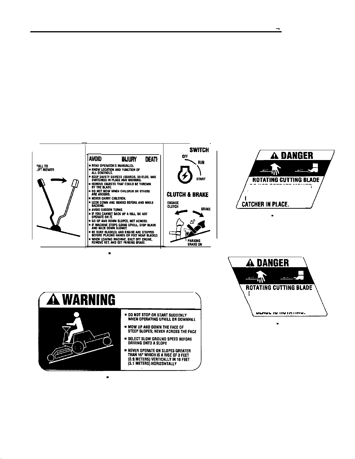
Safety Decals
This unit has been designed and manufactured to provide you with the safety and reliability you would expect
from an industry leader in outdoor power equipment
manufacturing.
Although reading this manual and the safety instructions
it contains will provide you with the necessary basic
knowledge to operate this equipment safely and effec-
tively, we have placed several safety labels on the unit to
remind you of this important information while you are
operating your tractor.
All WARNING, CAUTION and instructional messages on
-I-
MOWER LIFT
A WARNING
lAVOl0 SERIOUS lNJURY OR OEATl
IGNITION SWITCH-
your tractor and mower should be carefully read and
obeyed. Personal bodily injury can result when these
instructions are not followed. The information is for your
safety and it is important! The safety decals shown below
are on your tractor and mower.
If any of these decals are lost or damaged, replace them
at once. See your local dealer for replacements.
These labels are easily applied and will act as a constant
visual reminder to you, and others who may use the
equipment, to follow the safety instructions necessary for
safe, effective operation.
OFF
\
““I1
DO NOT OPERATE MOWER
WITHOUT DEFLECTOR
OR ENTIRE GRASS
Decal - Operating Information
Part No. 1708280
(AW~RNING
Decal
- Slope Operation
Part No. 1768280
Decal
Part No. 1704277
DO NOT PUT HANDS
OR
MOWER DECK WHILE
- Danger
FEET UNDER
BLADE IS ROTATING.
Decal - Danger
Part No. 1704276
Page 10

CONTROLS
REF NAME
A Engine Speed Control Lever
B
Headlight Switch
C
Traction/Mower Transport Lever
D
G
Ground Speed Control Lever Controls ground speed and forward reverse motion. Push forward to go forward,
E
PTO (Electric Clutch) Switch Controls PTO for mowing. Pull up and push forward to engage mower. pull
F
Oil Pressure Light (Red)
Mower Height Adjustment Lever Controls height of mower cut. Seven cutting height positions from 1 -I/4” to 4”.
FUNCTION
Controls engine speed.
Push forward to turn headlight on, pull back to turn headlight off.
Raises
onto front drive wheels for additional traction.
pull back to go in reverse. Ground speed is controlled by how far lever is in
forward or reverse gate.
backwards to
Indicates low oil pressure when engine is running. Lights up with ignition key
turned on and should go out immediately after engine starts.
Place in forward slot for lowest cut.
mcwer
for transport. Pull back slightly to transfer weight of mower deck
disenage.
Activates PTO light
(K)
Figure 2. Controls
6
Page 11

ENGINE
Featms & Controls
Figure 2.16 HP Engine Compartment
Page 12
Features & Controls
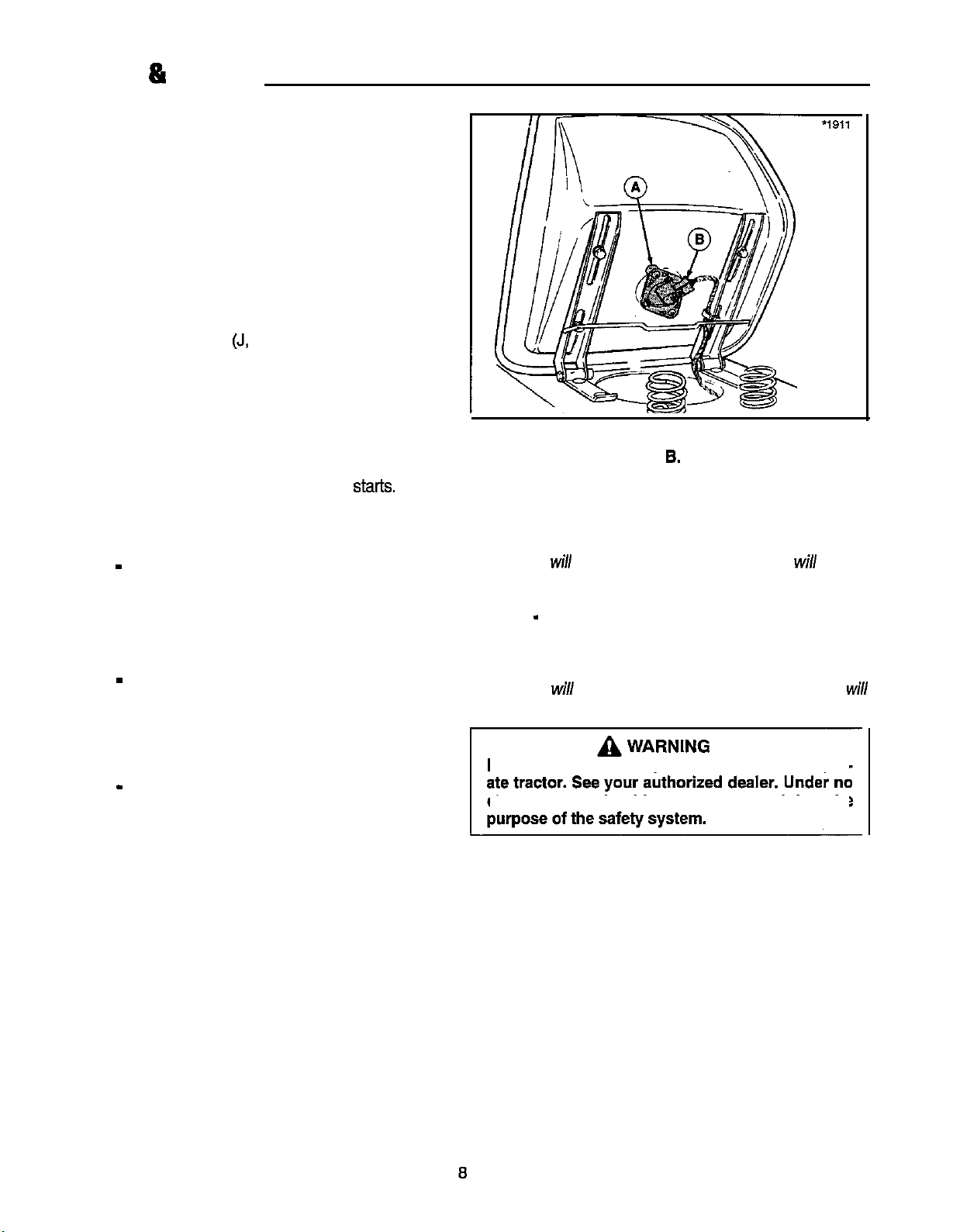
SAFETY INTERLOCK SYSTEM
Your rider is equipped with a seat switch safely system
that will automatically shut the engine off when the oper-
ator leaves the seat with the transmission control lever in
gear or PTO engaged. Once the engine has stopped, the
electric PTO switch must be turned off (after operator
returns to the seat) in order to start the engine.
Check operation of dash safely lights. With operator in
seat and ignition switch turned to ON (engine not running):
A. Neutral Indicator Light (J, figure 1) should go on with
transmission lever in neutral gate and should go out
when lever is moved to either the forward or reverse
gate.
B. PTO Light (K, figure 1) should go on and off with
operation of PTO switch.
C. Oil Pressure Light (F, figure 1) should be on and
should go out immediately after engine
Check the seat switch (A, figure 3) every fall and spring
with the following four tests:
Test 1 - Engine should NOT crank if:
A. seat is not occupied or
B. transmission lever out of neutral or
C. PTO switch engaged.
Test 2 - Engine should crank if:
A. seat is occupied and
B. transmission lever is in neutral and
C. PTO switch is disengaged.
Test 3 - Engine should shut off if:
A. operator rises off seat with transmission lever in
gear or
starts.
Figure 3. Seat Switch
A. Switch 8. Wiring Harness
B. operator rises off seat with PTO engaged.
NOTE: If operator returns to seat before engine stops,
the engine
will
re-start and electric PTO clutch
will
re-
engage.
Test 4 - PTO will disengage if:
A. operator rises off seat with engine running.
NOTE; If operator returns to seat before engine stops,
the engine
re-engage.
If the tractor does not pass the test, do not oper-
circumstance should you attempt to defeat the
will
resume speed and electric PTO clutch
will
Page 13

GENERAL
Before operating this rider for the first time, the owner
should operate in an open area without mowing, to
become accustomed to the unit. The left side of the
mower can be used to trim close to objects. Be sure to
read all information in the Safety and Operation sections
before attempting to operate this rider and mower.
g
WARNING - SLOPE OPERATION
Never operate on slopes greater than 30 percent
(16.7’) which Is a rise of three feet vertically in 10 feet
horlzontally. Select slow ground speed before driving
onto slope. Use extra caution when operating on
slopes with rear-mounted grass catcher. Mow UP and
DOWN the slope, never across the face, use caution
when changing directions and DO NOT START OR
STOP ON SLOPE.
lowing the rider will cause transmission damage. Do not use another vehicle to push or pull
To reduce fire hazard, keep the engine and
mower free of grass, leaves and excess grease.
The Interlock safety switches are for your safety.
Do not attempt to bypass them.
Operation
Never allow passengers to ride on the unit.
WARNING
A
WARNING
A
gure 5. PTO Wire Harness
Harness Plug C. Ties
I
Figure 4. Belt Installation
A. PTO (Electric Clutch) C. Belt Stop
B. Idler Pulley
-
MOWER INSTALLATION
Stop engine and remove key Do not engage PTO
until mower is completely installed and operator
1 is seated.
A
NOTE: Perform mower installation on a hard, level sur- 4. Install rod to PTO as shown in figure 6. Insert other
face such as a concrete floor.
wARNING
B. Belt Stop
1.
Position mower deck directly in front of rider.
2. Route belt underneath rider and over the drive axle.
Install mower belt around bottom pulley (V-side) of
PTO. Refer to figure 4.
3. Connect wire harness for PTO as shown in figure 5.
Secure wire to belt stop with reusable ties. If ties are
damaged, tape wire securely at top and bottom of
belt stop.
end through frame and secure with spring clip.
9
Page 14
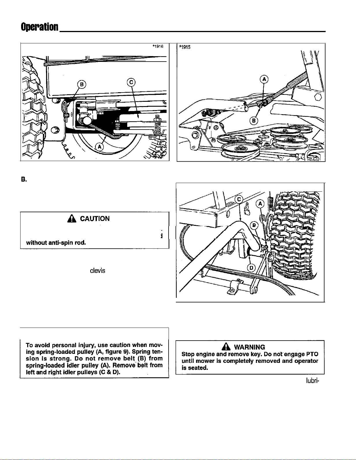
Figure 6. Anti-Spin Rod
A. Anti-Spin Rod c. PTO
6. Spring Clip
5. Connect top and bottom halves of mower lift arms.
See figure 7.
Anti-spin rod must be installed for operation
PTO will be immediately damaged if operated
6. Install mower hitch arms to rider hitch arms. See figure 8. Make sure large washer (D) is placed on rider
hitch arms. Secure with
7. See figure 9. Connect top link of chains (E) to weld
studs and secure with washers and cotter pins.
6. Install belt on right-hand and left-hand idler pulley by
pulling on spring-loaded idler pulley (A, figure 9).
9. Check mower belt routing carefully. Belt should be
positioned as shown in figure 10.
clevis
pins and spring clips.
Figure 7. Lift Arm Halves
A. Weld Stud B. Spring Clip
1914
I
Figure 8. Hitch Arms
A. Spring Clip C. Mower Hitch Arm
B. Clevis Pin D. Washer
WARNING
1
10. Make sure deflector is properly installed.
A
MOWER REMOVAL
1. Mower can be easily removed and installed for
cation, service and year-end storage.
2. Remove hardware securing belt covers to mower
deck. Refer to figure 12. Remove belt covers.
Diagram is located on underside of belt cover.
10
lubri-
Page 15

Figure 9. Removing Belt Tension
A. Spring-Loaded
Idler Pulley
B. Belt G. Rider Lift Arm
C. R.H. Idler Pulley H. Weld Stud
D. L.H. Idler Pulley
E. Chain
F. Mower Lift Arm
I.
Cotter Pin
Operation
Electric Clulch
FRONT
I
Figure 10. Mower Belt Routing
3. Place mower in lowest cutting position. To provide
slack, pull spring-loaded idler pulley away from belt
and remove belt from around left and right hand idler
pulleys.
A
I
Use caution when moving spring-loaded pulley
(A, figure 9). Spring tension is strong. Do not
remove belt
(A). Remove belt from
(C & D).
4. See figure 9. To remove ChainS trOm rider litt arms,
remove cotter pins
(H). Replace washers and pins on weld studs.
5. See figure 6. Remove the spring clips (A) and clevis
pins (B) from mower hitch arms (C). Drop mower
hitch arms and remove large washer (D) from rider
hitch arm. For storage, install clevis pin (B) and
spring clip (A) onto mower hitch arm with large wash-
er (D) in between hardware.
6. See figure 7. Disconnect the top
of the mower lift arm. Install spring clip onto weld
stud.
7. See figure 6. Remove the spring clip from anti-spin
rod outside rider frame. Push rod through frame and
disengage other end from PTO.
CAUTION
(B)
from spring-loaded idler pulley
left and
(I)
and washers from weld studs
right idler pulleys
and.bottom
halves
I
Figure 11. Belt Cover Removal
A. Flange Whiz Nut, l/Z
B. Flange Whiz Nut, 9/16
C. Large Washer
8. See figure 5. Disconnect wiring harness from PTO
harness plug. Remove the ties securing harness to
belt stop.
9. See figure 4. Remove mower belt from bottom pulley
(V
side) and idler pulley (flat side). Hardware securing belt stop may need to be loosened to remove
belt.
10. Mower deck can now be rolled forward from underneath rider.
D. Taptite Screw,
E. Taptite Screw, i/2
F. Flat Washer
316
11
Page 16

Operation
OPERATING THE MOWER
1. When traveling to or from the work site, fully raise the
mower using the mower transport lever (C, figure 13).
At the work site, lower mower using the lift lever.
2. Use the mower height adjustment lever (G, figure 13)
to set the proper mowing height. See Mowing
Patterns &Tips section for cutting height recommen-
dations.
CHECKS BEFORE STARTING
1.
See SLOPE OPERATION in the Safety Rules sec-
tion Make sure any slopes are within required limits,
2. Check that crankcase is filled to full mark on dipstick.
See the engine manual for instructions and oil recommendations.
3. Make sure all nuts, bolts, screws and pins are in
place and tight.
4. Make sure you can reach all controls from operator’s
positions. If not, see SEAT ADJUSTMENT.
5. Fill the gasoline tanks with fresh gasoline. Fill to bot-
tom of filler neck to avoid spillage and overflow. DO
NOT mix oil with gasoline. Refer to engine manual for
gasoline recommendations.
CLUTCH/BRAKE PEDAL OPERATION
WARNING
A
Gasoline is highly flammable and must be handled with care. Never fill the tank when the
engine is still hot from recent operation. Do not
allow open flame, smoking or matches in the
area. Avoid over-filling and wipe up any spills.
I. See figure 12. Depressing the pedal from position A to
B disengages the transmission. Fully depressing the
pedal to position C applies the tractor brake.
2. Parking brake is applied at pedal position C when
pedal is latched over footrest as shown in figure 12.
STARTING THE ENGINE
Refer to figure 13.
1. Seat yourself on the rider seat in the operating position.
2. Pull back on the switch (E) to disengage the’PT0 and
place the ground speed control lever (D) in neutral.
3. For cold starts, pull choke knob (M) out to the choke
position. For warm starts, leave choke knob pushed
in.
‘_
‘7
I
Figure 12. Clutch/Brake Pedal
4. Turn the ignition key (L) to start and release when
5. Move the engine speed control lever (A) to the slow
SELECTING GROUND
8c
Ground speed is infinitely variable according to how far
the control lever (D, figure 13) is moved in the forward or
reverse position.
1. If you are ready to mow, lower the mower from the
2. Set the engine speed control lever (A, figure 13) for
3. Use the PTO switch (E, figure 13) to engage the
4. Release the parking brake by depressing
923
engine has started.
position. Warm up the engine by running it for at least
a minute before engaging the PTO or driving the
rider.
ENGINE SPEED
WARNING
A
Make sure desired direction of travel is clear of
objects, people and animals.
transport position using lever (C, figure 13) and set
the mowing height using the mowing height adjuster
(G, figure 13).
full speed.
PTO.
clutch/brake pedal (H, figure 13).
12
Page 17

-
A.
Engine Speed Control Lever
B. Headlight Switch
C. Mower Transport Lever
D. Ground Speed Control Lever
E. PTO Switch
F.
Oil Pressure Light (Red)
G. Mower Height Adjustment
Lever
H. Clutch/Brake Pedal
I.
Parking Brake Lever
J. Neutral Light (Green)
K. PTO Light (Red)
L.
ignition Switch & Key
M. Choke Knob
Operation
Figure 13. Controls
5. Move the ground speed control lever (D, figure 13) to 4. Set the engine speed control lever (A, figure 13) to
the desired direction and speed of travel to set the
rider in motion.
6. Adjust engine speed control lever (A, figure 13) to the
desired speed. Between
mended for mowing.
3/4
and full speed is
recom-
STOPPING THE RIDER
1.
Move the ground speed control iever(D, figure 13)
into the NEUTRAL position to make a gradual stop.
To make a more rapid stop, depress the clutch/brake
pedal
(l-t,
figure 13).
2. Engage the parking brake by fully depressing
clutch/brake pedal and locking it over the footrest.
3. Use the PTO switch (E, figure 13) to disengage the
PTO.
l/2
throttle setting and allow the engine to idle for 20
seconds. Stopping a hot engine too fast may cause
engine damage.
5. Turn key (L, figure 13) to OFF and remove it.
WARNING
A
Before leaving the operator’s
reason, engage the parking brake, disengage the
PTO, stop the engine and remove the key.
WARNING
A
To reduce fire hazard, keep the engine, rider and
mower free of grass, leaves and excess grease.
Do not stop or-park rider over dry leaves, grass
or combustible materials.
13
~position
for any
Page 18

Operation
Figure 14.
A. Release Lever
B.
Plunger
C. Bracket
Transexle
Release Lever Engaged
PUSHING THE RIDER BY HAND
To push the rider by hand, the hydro release valve must
be engaged so
sion is depressed (figure 14). To drive the rider, the
release valve must be disengaged (figure 15).
1.
See figure 14. To engage the release lever (A), pull
the lever toward the left to clear pump bracket (C),
then flip it up so the lever depresses the plunger.
that’the
plunger on front of the transmis-
Figure 15. Transaxle Release Lever Disengaged
A. Release Lever
B. Plunger
C. Bracket
2. See figure 15. To disengage the release lever, pull
the lever toward the left, then flip it down. Push the
lever towards the right to secure it into
postion.
14
Page 19

Mowing Patterns 8 lips
For the first use of the mower, choose a smooth level
*
Aerate lawn in spring, consider renting an aerator
area. Cut long straight strips overlapping slightly.
The size and type of area to be mowed determines the
best mowing pattern to use. Obstructions such as trees,
fences and buildings must also be considered. Where
*
possible, make one or two passes in a counterclockwise
Don’t over-water. Too much water can encourage
direction around the outside of the area to keep the cut
grass off fences and walks. The remainder of the mow-
f Mow when the grass is dry, preferably in the late
ing should be done in a clockwise direction so the clippings are dispersed on the cut area.
*
Where possible, change patterns occasionally to
Keep in mind the following lawn care and mowing tips:
*
Too much maintenance is as detrimental to your lawn
as neglect.
*
Mow when grass is 3-5 inches tall. Don’t cut shorter
than 2 to
2-112
inches. Cut only the top one-third of the
*
For wet grasses, grasses prone to wheel tracking and
grass blade. Cutting below this level can lead to thatch
problems. Your mower has a cutting height adjustment
that can help you maintain a proper length.
*
For extremely tall grass, set the cutting height at
maximum for the first pass, and then reset to the
desired height and mow again.
*
Mow often. Short clippings of an inch or less decom-
pose more quickly than longer blades.
*
Keep the blades on your mower sharp for finer clip-
l
pings.
*
Let grass grow a bit longer when it is hot to reduce
heat build-up and protect grass from heat damage.
*
Use slow-release fertilizer for slow, even growth.
l
Don’t cover grass surface with a heavy layer of clippings. Consider using a grass collection system and
starting a compost pile.
which removes cores of soil from the lawn. This
increases the speed of clipping decomposition and
deep root growth by opening up the soil and permitting
greater movement of water, fertilizer and air.
disease development.
afternoon when the temperatures are cooler.
eliminate matting, graining or a corrugated appearance.
for collecting clippings:
a. Use sharp blades.
b. Raise deck
l/4”
higher in front than in rear.
c. Run at maximum engine speed but slow ground
speed.
d. Clean deck of built-up material/caked-on grass.
e. Check for free movement of mower idler pulley.
For dry conditions where grass blow-out is a problem:
a. Use sharp blades.
b. Raise deck so the front is even with, or
i/8”
lower
than, rear.
c. Use
314
engine speed.
d. Clean deck of built-up material/caked-on grass.
15
Page 20

NormalCare
SCHEDULE
The following schedule should be followed for normal care of your rider and mower. You will need to keep a record of
your operating time. Determining operating time is easily accomplished by multiplying the time it takes to do one job
by the number of times you’ve done the job.
Check tire pressure.
Change transmission
Clean battery &cables.
Clean/sharpen blades.
Inspect spark plug(s).
*
See the engine manufacturer’s owner’s manual.
n
Change original engine oil after first 5 hours of operation.
*
More often in hot (over 85’ F: 30” C) weather or dusty operating conditions.
-
Transaxle is a sealed unit and requires no regular
fluid.-
16
18
19
*
. .
interval fluid changes.
CHECKING/ADDING GASOLINE
Check the gas tanks (located on each side of seat deck)
to make sure there is enough gasoline to complete the
job. To add gasoline, remove the gas cap from each
tank. Do not overfill. Leave room in the tanks for fuel
expansion. Refer to your engine manual for gasoline recommendations. Install and hand tighten the gas caps.
A
CAUTION
Never use gasoline containing METHANOL, gaso-
hol containing more than 10% ethanol, gasoline
additives, premium gasoline, or white gas because
engine/fuel system damage could result.
-.
Only if transsxle is serviced.
.
.
.
LUBRICATION
Lubricate the rider and mower as shown in figures 16
24. When a grease gun is shown, wipe the fitting clean,
apply two or three shots of lithium base automotive
grease, and wipe off excess grease. When an oil can is
shown, wipe the area clean, apply a few drops of oil
(SAE
30),
then wipe up drips or spills.
-
CHECKING TIRE PRESSURE
Front tire pressure should be 8 to 12 psi. Rear tire pres-
sure should be 18 to 22 psi.
Figure 16. Lubricate Brake Pedal Pivot Point
Page 21

-
Normal Care
Figure 17. Lubricate
Figure 18. Lubricate Steering Arm and Axle Pivot
Hydra
Release Valve
Figure 20. Lubricate Lift Lever
Figure 21. Lubricate Rear Axle and Spindles
Figure 19. Lubricate Chain
Figure 22. Lubricate Steering Gear and Brake/Clutch
Rod Pivot Points
17
Page 22

NormalCare
gure 23. Lubricate Mower Pivot Points
Figure 24. Arbor Grease Fittings
BAlTERY MAINTENANCE
A
WARNING
Be careful when handling the battery. Avoid
spilling electrolyte. Keep flames and sparks
away from the battery.
Checking the Battery Fluid
1. Raise the rear platform to locate the battery.
2. Remove battery filler cap. Fluid must be even with split
ring full mark. If not, add distilled water.
3. Reinstall filler cap.
Cleaning the Battery and Cables
1. Disconnect the cables from the battery, negative
cable first (B, figure 25).
WARNING
A
When removing or installing battery cables, dis-
connect the negative cable FIRST and reconnect
it LAST. If not done in this order, the positive
minal can be shorted to the frame by a tool.
ter-
Figure 25. Battery
A. Positive Terminal
B. Neaative Terminal
CHECK TRANSMISSION FLUID LEVEL
Allow
accurate check.
C. Strap
D. Vent Tube
rider to cool after operation. Fluid must be cool for an
2. Slip the battery straps off, disconnect the vent tube,
then remove the battery.
3. Scrub the battery, cables and battery compartment
with baking soda and water.
4. Clean the battery teninals and cable clamps’with a
wire brush and battery post terminal cleaner.
5. Reinstall battery, vent tube and straps.
6. Connect cables, positive cable first.
7. Coat cable clamps and terminals with grease or
petroleum jelly.
I.
Raise the seat deck.
2. The fluid level is visible in the reservoir
without removing the cap. The level shduid ce at
COLD mark. If not, go to step 3.
3.
Clean the area around the reservoir and remove the
cap. Add multi-purpose
required. See your dealer for recommendation.
NOTE: In extemely hot weather, 30W oil may be used for
hydro pump. Do not mix multi-purpose oil with 30W oil.
Drain hydro system comp/ete/y and refill with appropriate oil.
4. It will take awhile for the oil to seep through a filter
18
hydrauli&ansmission
(B.
fiaure 26)
oil as
FLJLL
Page 23

Figure 26. Hydrostatic Reservoir
A. Cap
screen into the reservoir. Check the level again after
operating the rider a few times. If level is consistently
low, see your dealer to check for leaks.
5.
Keep cooling fins and fan cover free of grass and dirt.
B. Reservoir
-
Normal Care
Figure 27. Removing The Blade
SERVICING THE MOWER BLADES
AWARNING
For your personal safety, do not handle the
sharp mower blades with bare hands. Careless
or improper handling of blades may result in
serious injury.
1.
Remove mower from the tractor.
2. Blades should be sharp and free of nicks and dents.
If not, sharpen blades as described in following steps.
3. To remove blade for sharpening, use wooden block
to hold blade while removing the blade mounting
screw (figure 27).
4. Use a file to sharpen blade to fine edge. Remove all
nicks and dents in blade edge. If blade is severely
damaged, it should be replaced.
5. Balance the blade as shown in figure 26. Center the
blade hole on a nail lubricated with a drop of oil. A
balanced blade will remain level.
6. Reinstall each blade with the tabs pointing up toward
deck as shown in figure 29. Secure with a
(D), cup washer (C) and spline washer (B). Use a
wooden block to prevent blade rotation and torque
capscrews to 50-70
ft.lbs.
(67-95
‘.
N.m.).
cap-
capscrew
Figure 26. Balancing The Blade
Figure 29. Installing The Blade
A. Wooden Block
B. Spline Washer
A
For your personal safety, blade mounting
screws must each be installed with a cup washer
and spllne washer, then securely tightened.
Torque blade mounting
(67-96
N.m.)
C. Cup Washer
D.
WARNING
capscrew
Capscrew
to 50-70
cap-
ft.lbs.
19
Page 24

WARNING
A
Never store the rider, with gasoline In engine or fuel tank, in a heated shelter or in enclosed, poorly ventilated enclosures. Gasoline fumes may reach an open flame, spark or pilot light (such as a furnace, water
heater, clothes dryer, etc.) and cause an explosion.
Handle gasoline carefully. It is highly flammable and careless use could result in serious fire damage to
your person or property.
Drain fuel into an approved container outdoors away from open flame or sparks.
TEMPORARY STORAGE
(30 Days Or Less)
Remember, the fuel tank will still contain some gasoline,
so never store the rider indoors or in any other area
where fuel vapor could travel to any ignition source. Fuel
vapor is also toxic if inhaled, so never store the rider in
any structure used for human or animal habitation.
Here is a checklist of things to do when storing your rider
temporarily or in between uses:
. Keep the rider in an area away from where children
may come into contact with it. If there’s any chance of
unauthorized use, remove the spark plug (s) and put
in a safe place. Be sure the spark plug opening is
protected from foreign objects with a suitable cover.
. If the rider can’t be stored on a reasonable level sur-
face, chock the wheels.
*
Clean all grass and dirt from the mower.
LONG TERM STORAGE
(Longer Than 30 Days)
Before you store your rider for the off-season, read the
Maintenance and Storage instructions in the Safety
Rules section, then perform the following steps:
1,
Drain crankcase oil while engine is hot and refill with
a grade of oil that will be required when rider is used
again.
2. Prepare the mower deck for storage as follows:
a. Remove mower deck from the rider.
b. Clean underside of mower deck.
%.
3. Clean external surfaces and engine.
4. Prepare engine for storage. See engine owner’s
manual.
5. Clean any dirt or grass from cylinder head cooling
finsengine housing and air cleaner element.
6. Cover air cleaner and exhaust outlet tightly with plastic or other waterproof material to keep out moisture,
dirt and insects.
7. Completely grease and oil rider as outlined in the
Normal Care section.
8. Clean up rider and apply paint or rust preventative to
any areas where paint is chipped or damaged.
9. Be sure the battery is filled to the proper level with
water and is fully charged. Battery life will be
increased if it is removed, put in a cool, dry place and
fully charged about once a month. If battery is left in
rider, disconnect the negative cable.
10. Drain fuel system completely or add a gasoline stabilizer to the fuel system. If you have chosen to use a
fuel stabilizer and have not drained the fuel system,
follow all safety instructions and storage precautions
in this manual to prevent the possibility of fire from
the ignition of gasoline fumes. Remember, gasoline
fumes can travel to distant sources of ignition and
ignite, causing risk of explosion and fire.
NOTE: Gasoline, if permitted to stand unused for
ed periods (30 days or more), may develop gummy
deposits which can adversely affect the engine carbure-
tor and cause engine malfunction. To avoid this condition, add a gasoline stabilizer to the fuel tank or drain all
fuel from the system before placing unit in storage.
exfend-
c. Coat all bare metal surfaces with paint or.light coat
of oil to prevent rusting.
20
Page 25

11. Transport the rider to a suitable, dry, indoor location.
If the rider is to be stored 6 months or longer, block
the rider up off the wheels to relieve weight and also
to keep the tires off a damp floor. Protect tires from
prolonged exposure to direct sunlight.
2. Install the battery if it was removed.
3. Unplug the exhaust outlet and air cleaner.
4. Fill the fuel tank with fresh gasoline. See engine
5. Check crankcase oil level and add proper oil if
STARTING AFTER
LONG TERM STORAGE
Before starting the rider after it has been stored for a
long period of time, perform the following steps.
1. Remove the blocks from under the rider.
6. Inflate tires to proper pressure. Check fluid levels.
7. Start the engine and let it run slowly. DO NOT run at
manual for recommendations.
necessary.
high speed immediately after starting. Be sure to run
engine only outdoors or in well ventilated area.
21
Page 26

Troubleshooting & Repair
GENERAL
WARNING
A
To avoid serious injury, perform maintenance on
the rider or mower only when the engine is
stopped and the parking brake engaged. Always
remove the ignition key, disconnect spark plug
wire and fasten away from the plug before begin-
ning the maintenance, to prevent accidental
starting of the engine.
This section of the manual provides troubleshooting and
repair instructions for the more common and easily
rected problems. For other problems, it is recommended
that you contact your dealer. Locate the problem that
best describes the trouble that you have encountered.
Check the possible causes one at a time, in the order
that they are listed.
cor-
2. Carburetor adjusted incorrectly. See engine manual.
3. Spark plugs faulty, fouled, or incorrectly gapped.
Engine knocks.
1. Low oil level. Check/add oil as required.
2. Using wrong grade oil. See engine manual.
Excessive oil consumption.
I.
Engine running too hot. Clean engine fins, blower
2. Using wrong weight oil. See engine manual.
3. Too much oil in crankcase. Drain excessive oil.
Engine exhaust is black.
1.
Dirty air filter. Clean air filter. See engine manual.
2. Check engine speed control adjustment (choke).
TROUBLESHOOTING THE RIDER
Engine will not turnover or start.
1.
Ground speed control lever not in neutral-start position.
Shift into neutral.
2. PTO (electric clutch) switch in ON position. Place in
OFF position.
3.
Out of fuel. If engine is hot, allow it to cool, then refill the
fuel tank(s).
4. Engine flooded. Push choke knob in.
5. Circuit breaker tripped. Wait one minute for automatic
reset. Replace if defective (see your dealer).
6. Battery terminals require cleaning. See Normal Care
section.
7. Battery discharged or dead. Recharge or replace.
8. Wiring loose or broken. Visually check wiring & replace
broken or frayed wires. Tighten loose connections.
9. Solenoid or starter motor faulty. Repair or replace.
10. Safety interlock switch or module faulty. Replace if
needed (see your dealer.)
11.
Spark plugs faulty, fouled or incorrectly gapped. Clean
and gap or replace. See engine manual.
12. Water in fuel. Drain fuel
13. Old stale gas. Drain fuel & replace with fresh.fuel.
14. Foot pedal not depressed.
&
refill with fresh fuel.
Engine starts hard or runs poorly.
1. Fuel mixture too rich. Clean air filter. Check choke
adjustment. See engine manual.
Engine runs, but rider will not drive.
1.
Ground speed control lever in neutral. Shift in forward
2. Transmission release lever in “push” position. Move
3. Belt is broken. See Rider Drive Belt Replacement.
4. Drive belt slips. See problem and cause below.
5. Brake is not fully released. See Clutch/Brake
Rider drive belt slips.
1.
Clutch is out of adjustment. See your dealer.
2. Pulleys or belt greasy or oily. Clean as required.
3. Belt stretched or worn. Replace with correct belt.
4. Idler pulley pivot bracket “frozen” in declutched
Brake will not hold.
1. Brake is incorrectly adjusted. See Clutch/Brake
2. Internal brake disc on transaxle worn. See your
Rider steers hard or handles poorly.
1.
Steering linkage is loose. Check and tighten any
2. improper tire inflation. Check and correct.
3. Spindle bearings dry. Grease spindles.
Clean and gap or replace. See engine manual.
screen and air cleaner.
See engine manual.
or reverse.
into drive position.
Adjustment.
posi-
tion. Remove idler pulley, clean and lubricate.
Adjustment.
dealer.
loose connections.
22
Page 27

Troubleshooting & Repair
Drive belt does not stop when clutch/brake
pedal depressed.
1. Belt stops or belt tension out of adjustment. See
Rider Drive Belt in Belt Replacement section.
TROUBLESHOOTING THE MOWER
Mower will not raise.
1.
Lift arms or lift link damaged or not properly attached.
Attach or repair.
Excessive belt breakage.
1.
Belt tension too tight. Adjust belt tension.
2. Bent or rough pulleys. Repair or replace.
3. Using incorrect belt, See your dealer.
Mower drive belt slips or fails to drive.
1. Idler pulley spring broken or not properly attached.
2. Belt stops out of adjustment. Check.
3. Mower drive belt broken. Replace.
Mower cut is uneven.
1. Mower not leveled properly. See Mower Adjustments.
2. Tires not inflated equally or properly. See Normal
Care.
Mower cut is rough looking.
1.
Engine speed too slow. Set for
2. Ground speed too fast. Set ground speed control
lever at a slower ground speed.
3. Blades dull and require sharpening. See Servicing
the Mower Blades.
4. Mower drive belt slipping. Belt oily or worn. Clean or
replace belt as necessary.
5. Check PTO (Electric Clutch) Adjustment. Clutch may
need to be adjusted.
6. Blades not properly fastened to arbors. See Servicing
the Mower Blades.
3/4
to full speed.
CHECKING THE BAlTERY
The voltmeter can be used to determine condition of battery. When engine is off, the voltmeter shows battery
voltage, which should be 12 volts. When engine is running, the voltmeter shows voltage of charging circuit
which normally is 13 to 14 volts.
A dead battery or one too weak to start the engine may
not mean the battery needs to be replaced. It may, as an
example, mean that the alternator is not charging the
battery properly. If there is any doubt about the cause of
the problem, see your dealer. If you need to replace the
battery, follow the steps under Cleaning the Battery
Cables in the Normal Care Section.
CHARGING A COMPLETELY
DISCHARGED BA-ITERY
See your dealer.
&
Engine stalls easily with mower engaged.
1,
Engine speed too slow. Set for
2. Ground speed too fast.
3. Carburetor not adjusted properly.
4. Cutting height set too low when mowing tall grass.
Cut tall grass at maximum cutting height during first
pass.
5. Discharge chute jamming with cut grass. Cut grass
with discharge pointing toward previously cut area.
3/4
to full throttle.
Excessive mower vibration.
1. Blade mounting screws are loose. Tighten to 50-70
ft.lbs.
(74
N.m.).
2. Mower blades, arbors, or pulleys are bent. Check and
replace as necessary.
3. Mower blades are out of balance. Remove, sharpen
and balance blades. See Servicing the Mower
Blades.
4. Belt installed incorrectly. See Belt Replacement.
23
1.
Be aware of all the safety precautions you should
observe during the charging operation. If you are
unfamiliar with the use of a battery charger and
hydrometer, have the battery serviced by your dealer.
2. Add water sufficient to cover the plate (till to the proper level near the end of the charge). If the battery is
extremely cold, allow it to warm before adding water
because the water level will rise as it warms. Also, an
extremely cold battery will not accept a normal
charge until it becomes warm.
3. Always unplug or turn the charger off before attach-
ing or removing the clamp connections.
4. Carefully attach the clamps to the battery in proper
Page 28
Troubleshooting & Repair
WARNING
A
Keep open flames and sparks away from the bat-
tery; the gasses coming from it are highly explo-
sive. Ventilate the battery well during charging.
polarity (usually red to
negative).
5.
While charging, periodically measure the temperature
of the electrolyte. If the temperature exceeds 125” F
(51.6” C), or if violent gassing or spewing of
trolyte occurs, the charging rate must be reduced or
temporarily halted to prevent battery damage.
6. Charge the battery until fully charged
specific gravity of the electrolyte is 1.250 or higher
and the electrolyte temperature is at least
best method of making certain a battery is fully
charged, but not over charged, is to measure the
specific gravity of a cell once per hour. The battery is
fully charged when the cells are gassing freely at low
charging rate and less than 0.003 change in specific
gravity occurs over a three hour period.
[+]
positive and black to
(i.e.
[-I
elec-
until the
60” F).
The
JUMP STARTING WITH AUXILIARY
(BOOSTER)
For your personal safety, use extreme care when
jump starting. Never expose battery to open
flame or electric spark - battery action generates
hydrogen gas which is flammable and explosive.
Do not allow battery acid to contact skin, eyes,
fabrics, or painted surfaces. Batteries contain a
sulfuric acid solution which can cause serious
personal injury or property damage.
Jump starting is not recommended. However, if if must
be done, follow these directions. Both booster and discharged batteries should be treated carefully when using
jumper cables. Follow the steps below EXACTLY, being
careful not to cause sparks. Refer to figure 30.
1. Both batteries must be of the same voltage (6, 12,
etc.).
2. Position the vehicle with the booster baffery adjacent
to the vehicle with the discharged battery so that
booster cables can be connected easily to the batter-
ies in both vehicles. Make certain vehicles do not
touch each other.
BAlTERY
WARNING
A
3. Wear safety glasses and shield eyes and face from
batteries at all times. Be sure vent caps are tight.
Place damp cloth over vent caps on both batteries.
4. Connect positive (+) cable to positive post of dis-
charged battery (wired to starter or solenoid).
5. Connect the other end of same cable to same post
marked positive (+) on booster battery.
6. Connect the second cable negative
of booster battery.
7. Make final connection on engine block of stalled
cle away from battery. Do not lean over batteries.
8. Start the engine of the vehicle with the booster
tery. Wait a few minutes, then attempt to start the
engine of the vehicle with the discharged battery.
9.
If the vehicle does not
seconds, STOP PROCEDURE. More
onds seldom starts the engine unless some mechanical adjustment is made.
10. After starting, allow the engine to return to idle speed.
Remove the cable connection at the engine or frame.
Then remove the other end of the same cable from
the booster battery.
11.
Remove the other cable by disconnecting at the dis-
charged battery first and then disconnect the opposite end from the booster battery.
12. Discard the damp cloths that were placed over the
battery vent caps.
Any procedure other than the preceding could
result In: (1) personal injury caused by elec-
trolyte squirting out the battery vents, (2) per-
sonal injury or property damage due to battery
explosion, (3) damage to the charging system of
the booster vehicle or of the immobilized vehicle.
Do not attempt to jump start a vehicle having a
frozen battery because the battery may rupture
or explode. If a frozen battery is suspected,
examine all fill vents on the battery. If ice can be
seen or if the electrolyte fluid cannot be seen, do
not attempt to start with jumper cables as long
as the battery remains frozen.
WARNING
A
start
after
(-)
to other post
crankina
than
bat-
for thirtv
thirty
vehi-
set-
24
Page 29

TO
TO
Ground
Troubleshooting & Repair
Y582
THIS HOOK-UP FOR NEGATIVE GROUND VEHICLES
MAKE CERTAIN VEHICLES DO NOT TOUCH
Figure 30. Battery Jump Starting Diagram
25
Page 30

Adjustments
WARNING
A
To avoid serious injury, perform adjustments
only with engine stopped, key removed and tractor on level ground.
SEAT ADJUSTMENT
1.
Unlatch seat by pushing down on seat back and
unhooking latch bar (A, figure 31).
2. The seat can be moved forward or back for operator
comfort. Loosen the four screws, move the seat to
the desired position then tighten screws.
3. Make sure there is enough slack in the wiring harness to accommodate seat adjustment.
4. The springs (C, figure 31) can be moved to forward
holes for lighter operator. Pull up on springs to relocate.
5. Lower seat and make sure latch bar locks in place
after adjustment.
I
Figure 31. Seat Adjustment
A. Latch Bar
B. Capscrews
\
C. Springs
D. Wiring Harness
NEUTRAL ADJUSTMENT
It is necessary to have the engine running while
performing certain steps in this adjustment procedure. To avoid serious injury, keep away from
If the tractor moves forward or backward with the
ground speed control lever positioned in the neutral gate, perform the following adjustment.
Adjustment can be performed with the mower
installed.
1. See figure 32. Loosen the nuts
guide (C). Leave
2. Loosen the two capscrews (A, figure 33).
3. Raise front tires off the ground by placing jack stands
under each side of frame. Do not support rider at
axle, as the axle will rotate during this adjustment.
4. Start the engine and raise the seat deck. For an
accurate neutral adjustment, keep engine RPM level
high during adjustment.
5. See figure 33. Loosen the jam nut (B). Turn. the inner
nut (D) either left or right until the output pulley (C)
stops turning.
6. Tighten the two capscrews (A, figure 33). Tighten the
jam nut
7. Shut off the engine.
8. Make sure ground speed control lever is in neutral.
(6)
l/4”
clearance on each side.
against the inner nut (D).
(6)
on either side of
Figure 32. Hydro Control Rod
A. Control Rod
B. Nuts
igure 33. Neutral Adjustment
,.
Capscrews C. Pulley
:.
Jam Nut D. Adjustment Nut
C. Guide
26
Page 31

9. See figure 32. Hold guide (C) to keep it from rotating
and tighten nuts (B)
10.
Remove the rider from the jack stands.
CLUTCH/BRAKE ADJUSTMENT
1.
Release the parking brake.
2. The clutch rod spring (A, figure 34) should measure
l-3/1 8” to l-5/1 8” along the long side, between
insides of washers. Tighten or loosen nut (B, figure
34) to adjust.
3. Pull the brake rod (C, figure 34) toward front as far as
possible. Tighten or loosen nut (D, figure 34) to
achieve a gap of
the guide (E).
3/s”
between rear surface of nut and
PTO (ELECTRIC CLUTCH) ADJUSTMENT
1. Make sure engine is off and key removed.
2. Use a 0.010 - 0.012 feeler gauge to check the PTO at
three places. See figure 35. Insert the gauge
between the drive spring rivets. There should be a
slight resistance as gauge is moved in and out of slot.
If adjustment is required, proceed to step 3.
3. Loosen or tighten one of the nuts as required to
obtain the specified clearance. Loosen the nuts to
increase the gap, tighten the nuts to decrease the
gap.
4. After adjusting one nut, check the other two with a
feeler gauge. Adjustment at one location will change
the measurement at the other two locations. Make
sure all three locations have proper adjustment.
5. See Blade Brake Check on page 28.
Agjustments
‘igure 34.
‘igure 34.
A. Spring D. Nut
B. Nut E. Guide
C. Brake Rod
Figure 35. PTO Clutch Adjustment
A. Slot
Clutch/Brake Adjustment
Clutch/Brake Adjustment
6. Adjustment Nut
MOWER ADJUSTMENTS
WARNING
A
Before checking mower, shut off PTO and
engine. Allow all moving parts to stop. Remove
ignition key, then disconnect the spark plug
wires and fasten away from the spark plugs.
Leveling The Mower
If the cut is uneven, the mower may
Unequal or improper tire pressure may also cause an
uneven cut. Make sure tire pressure is correct as specified in Checking Tire Pressure.
1. With the mower installed, place the rider on a
smooth, level surface such as a concrete floor. Turn
the front wheels straight forward.
need
leveling.
Figure 36. Leveling Mower Side-to-Side
A.
27
Capscrew
B. Roller Bracket
Page 32

Adjustments
2. Check for bent blades and replace if necessary.
3. Disengage the PTO. Place the mower in high cut
position. Arrange the mower blades so that they are
pointing from side-to-side.
4. Measure the distance between the outside tips of
each blade and the ground. If there is more than i/s”
(3 mm) difference between the mesurements on each
side, proceed to step 5. If the difference is
or less, proceed to step 6.
5. See figure 36. Loosen the
hand side of mower roller bracket (B). Raise or lower
right-hand side of mower as necessary, then tighten
capscrew
NOTE: When using a turbo collection system, raise
the discharge side of the mower approximately
to compensate for turbo assembly weight. Check the
/eve/ of the cut grass and adjust the
ment as necessary for a smooth, even cut.
6. Disengage the mower PTO. Arrange the blades so
they face front-to-back, then engage the PTO.
7.
Measure the distance from the ground to the front tip
of the center blade, and from the ground to rear tips
of the left-hand and right-hand blades.
Center blade front tip should be
proceed with adjustment procedure.
8. Remove belt covers. See figure 37.
9. See figure 38. Remove the spring clip (A) and clevis
pin
(A).
(8)
from both adjustment rods (E).
capscrew
l/4”
(A) on the
i/8(3
right-
l/4”
measure-
higher. If not
mm)
l/4”
‘1927
:iaure 37. Belt Covers
A.-Flange Whiz Nut,
8. Flange Whiz Nut, l/2” E. Taptite Screw, l/2”
C. Large Washer
l/3”
-
D. Taptite Screw,
F. Flat Washer
318”
I
10. Loosen the jam nut (D) in front of clevis
11. Turn clevises an equal number of turns. Turn clevis
towards front to raise front of mower.
12. Install clevis to mower rollers with clevis pin and
spring clip. Check front-to-back measurements again.
If adjustment is correct, tighten jam nut (D) snug
against clevises.
13. Install belt covers.
Blade Brake Check
Mower blades and mower drive belt should come to a
complete stop within five seconds after electric PTO
switch is turned off.
1.
With
tractor in neutral, PTO disengaged and operator
in seat, start the rider engine.
2. Look over the left-hand footrest at the mower
belt. Engage the PTO and wait several seconds.
(C).
I
Figure 38. Leveling The Mower Front-To-Back
A. Spring Clip D. Jam Nut
B. Clevis Pin E. Adjustment Rod
C. Clevis
“_
3. If mower drive belt does not stop within five seconds,
cinve
Disengage the PTO and check the amount of time it
takes for the mower drive belt to stop.
perform the steps described under PTO (Electric
Clutch) Adjustment, then repeat steps 1 and 2. If belt
still does not stop within 5 seconds, see your dealer.
28
Page 33

Figure 39. Removing Belt Tension
A. Spring-Loaded
Idler Pulley
E. Chain
F. Mower Lift Arm
B. Belt G. Rider Lift Arm
C. R.H.
D. L.H. Idler Pulley
fdler
Pulley H. Weld Stud
I.
Cotter Pin
Belt Replacement
Figure 49. PTO Wiring Harness
A. Harness Plug C. Ties
B. Belt Stop
A
CAUTION
To avoid damaging belts, do not pry belts over
pulleys.
MOWER BELT
NOTE: Mower be/t can be rep/aced with mower deck
removed or installed to rider. If you wish to perform the
be/t replacement with deck off the rider,
follow
the procedure under Mower Removal before performing the following steps.
1. Park the rider on a smooth, level surface such as a
concrete floor.
and lock the parking brake. Remove the key.
Disengage the PTO, turn off the engine
-
2. Remove belt covers. See figure 37.
3. Remove belt from idler by pulling spring loaded idler
pulley to gain slack in belt. See figure 39.
WARNING
To avoid
perso&njury,
use
cautibn
when mov-
ing spring-loaded pulley (A, figure 39). Spring
tension is strong. Do not remove belt (B) from
spring-loaded idler pulley (A). Remove belt from
left and right idler pulleys (C & D).
Figure 41. Anti-Spin Rod
A. Anti-Spin Rod C. PTO
B. Spring Clip
r
I-
/
-
Ftat
Side
4. Remove ties securing PTO wiring harness to belt stop
and disconnect harness. See figure 40.
Figure 42. Belt Pulleys
A. PTO C. Belt Stop
B. Idler Pulley
29
Page 34

Belt Replacement
5. Remove anti-spin rod from frame and PTO. See figure
41.
6. Remove belt from PTO pulley. See figure 42.
Hardware securing belt stops may have to be loosened in order to remove belt.
7. Remove belt from mower deck and replace with a new
belt. Check belt pattern as shown in figure 43.
6. See figure 42. Make sure mower belt goes underneath
rider, and over the drive axle. Install belt around bot-
tom pulley of PTO.
CAUTION
A
Anti-spin rod must be reinstalled for operation.
PTO will be Immediately damaged if operated
without anti-spin rod.
9. See figure 42. Install anti-spin rod to PTO. Insert other
end through frame and secure with spring clip.
10. Connect wiring harness to PTO and secure it to the
belt stop with ties.
11.
Pull spring-loaded idler pulley back to gain slack, and
install belt on idler pulley. See figure 39.
FRONT
I
I
Figure 43. Mower Belt Routing
A
WARNING
A
To avoid personal injury, use caution when mov-
ing spring-loaded pulley (A, figure 40). Spring
tension is strong. Do not remove belt (6) from
spring-loaded idler pulley (A). Remove belt from
left and right idler pulleys (C & D).
12. Install belt covers. See figure 37. Make sure covers
and deflector are
RIDER DRIVE BELT
1.
Set the parking brake to provide slack in the belt.
2. See figure 44. Remove the screen (A) by removing
four capscrews (B); two at top and two at bottom.
3. Remove the fan (C) by removing one screw (D) in center. Keep washers (E) in proper order for reassembly.
4. Slip the belt
5. See figure 45. Remove belt (D) from idler pulley (C),
fixed pulley (B) and engine pulley (A). Loosen belt
stops as necessary.
6. Remove mower belt from PTO pulley by following the
procedure under Mower Belt.
orooerlv installed before ooeration.
I
(P)
from the transmission pulley.
I
Figure 44 Hydro Pump
A. Screen E. Washers
B. Capscrews
C. Fan
D. Capscrews
7. See figure 46. Place the new belt onto the engine pulley (A), fixed pulley (B) and idler pulley (C). Note that
the V side of belt rides in the pulley grooves and the
flat side rides against the fixed pulley
turns
8. Pull belt up from top and place onto the transmission
pulley (D, figure 46)
F. Belt
G. Belt Stop
(B).
The belt
900
between engine pulley and the fixed pulley
(B), and between engine pulley and idler pulley (C).
30
Page 35

Belt Replacement
Figure 48. V Belt (Shown from Underside of Rider)
A. Engine Pulley
B. Fixed Pulley D. Belt
9. Install mower belt to
dures under Mower Belt.
10.
Install fan with original hardware. Note that a tab on
the inner side of the fan fits into a hole when the fan is
properly installed.
11. Install the screen (A, figure 44) with two capscrews at
top and two capscrews at bottom.
12. Release parking brake to check belt stop adjustment.
There should be
and belt stops. Five belt stops are shown in figure 47.
13. See figure 48. Check belt stop at transmission pulley.
To adjust, loosen mounting hardware, position belt
stop, then tighten hardware.
14. Perform Clutch/Brake Adjustment as described in the
Adjustments section.
l/16” - i/8”
C. Idler Pulley
PTO
pulley. Follow the proce-
clearance between belt
Figure 48. Belt Pattern (Seen from R.H. Side)
A. Engine Pulley C. Idler Pulley
B. Fixed Pulley
1
-L
Figure 47. Belt Stop Locations
A. Belt Stops
D. Transmission Pulley
Figure 48. Transmission Pulley Belt Stop Location
A. Belt Stop B. V Belt
31
Page 36

Specifications
NOTE: Specifications are correct at time ofprinting and are subject to change without notice.
ENGINE
16 HP Briggs & Stratton
Make
Model
Horsepower
Cylinders
Bore
Stroke
Construction
Electrical
System
Ignition
Air Cleaner
Lubrication
Oil Capacity
Fuel Tank
Muffler
Briggs & Stratton
VanguardTM V-Twin
16 HP @ 3600 rpm
2
2.68 In. (68 mm)
2.60 In. (66 mm)
29.3 Cu. In. (480 cc)
Overhead Valve, Cast Iron
Sleeves, Aluminum Crankcase
12 Volt, 16 Amp Alternator
Regulated Battery: 340 Cold
Cranking Amps, 41 min.
Reserve Capacity, Industrial
Rated Starter Motor
Magnetron Electronic Ignition
Ducted
Foam Precleaner large
325
Full Pressure Lube w/ Oil Filter
3.5 Pints w/Filter (1.6 L)
Material: Non-Corrosive
Polyethylene Fuel Tank Gauge
Built Into Filler Cap Capacity: 4
Gallons (15.1 L)
Quiet Compact, Low Back
Pressure
TRANSMISSION
Type
Final Drive
Differential
Speeds
@moo
RPM
Hydrostatic, Infinitely Variable
#40
Bevel Gear Type
Forward: 0 - 5.5 MPH
Reverse: 0 - 2.6 MPH.
Paper Cartridge and
sq;
in. Air Filtering System
Chain
Front Axle
Seat Deck
Turning Radius
(inside Front Wheel)
3/4”
Axle Shaft w/Differential
12 Gauge, Hinged for Easy
Access
6 In. (15.2 cm)
DIMENSIONS
Tractor
Overall Length
Overall Width
-w/42”
Mower
-w/48”
Mower
Height at
-steering wheel
-steering column
-
seat back
-
engine cover
Wheel Base
Weight (approx.)
Mower - 42” Deck
Effective Cutting 42 In. (107 cm)
Width
Overall Width 57.5 In. (146.1 cm)
with Deflector
Weight 147 Ibs. (66.59 kg)
Variable Cutting Ht.
Blade Arrangement
Mower Drive
Spindle Bearings Lubricated and Sealed Ball
Mower - 48” Deck
Effective Cutting 48 In. (122 cm)
Width
Overall Width 63.5 In. (161.1 cm)
with Deflector
87.25 In. (221.8 cm)
57.5 In. (146.1 cm)
63.5 In. (161.3 cm)
40.5 In. (102.9 cm)
31.75 In. (80.6 cm)
37.25 In. (94.6 cm)
26.5 In. (67.3 cm)
40 In. (101.6 cm)
Net: 633 Ibs. (286.75 kg)
l-1/4 to
Three Staggered Blades
V-Belt From Tractor PTO Pulley
Bearings
lln.
(3.2 to 10.2 cm)
CHASSIS
Frame
Rear Wheels
Front Wheels
l/4”
Steel Rails, 12 Gauge
Engine Base
13 x 5.0-6, 18-22 psi
16 x 6.5-8, 8-12 psi
Weight
Variable Cutting Ht.
Blade Arrangement
Mower Drive V-Belt From Tractor PTO Pulley
Spindle Bearings Lubricated and Sealed Ball
32
:
156 Ibs.
i-1/4to Iln.
Three Staggered Blades
Bearings
(70.67 kg)
(3.2to
10.2cm)
Page 37

Parts & Accessories
COMMON REPLACEMENT PARTS
!&ted below are the more common replacement parts. Only
genuine factory replacement parts will assure optimum
mance
and safety. Do not attempt repairs or maintenance
unless proper procedures and safety precautions are followed. -SAE 30
For assistance in any area, see your dealer.
QTY.
3
3
1
1
1
1
2
2
1
1
1
1
1
1
1
DESCRIPTION
Mower Blades
- 42”
Mower
- 48”
Mower
Mower Belts
_
42” Mower Drive
-
48” Mower Drive
Drive Belt - Hydro Input
Drive Belt
Straight Pin, Mower Hitch Arms
Spring Clip, Mower Hitch Arms
Safety Clip
Key, Ignition
Interlock Switch, Seat
Battery
Solenoid
Switch, PTO (Electric Clutch)
Headlamp Bulb
-
Hydro Output
-
Mower Lift
perfor-
PART NO.
1656147
1656146
1703371
1703372
1704735
1713639
174215
1918196
176012
1704348
1703373
1685215
1685290
1679932
1679954
MAINTENANCE ITEMS
*
Simplicity Engine Oils
Case of 12 qts. (Your dealer has 1 qt. cans)
-SAE
5W30
- Touch-Un
Deep Orange Spray Paint, 13 oz. Can
Deep Orange Spray Paint
(Case of 12 -13 oz. Cans)
Deep Orange Paint, 1 qt.
White Spray Paint, 13 oz. Can
Red Spray Paint, 13 oz. Can
*
Touch-Up Daubers
Deep Orange
*
Grease Gun Kit w/8 oz. Grease Tube
Replacement 8 oz. Grease Tube for above 103077
*
Tire Sealant-Stops Tire Leaks. Prevents Flats.
11 oz. Tube
*
Gas Can-No Tip Design. Durable Polyethylene.
1 gallon
2-112
gallon
5-114
gallon
l
Cleaner, Polish, Sealant & Protectant
8 oz. Bottle
l
DegrimedDegreaser
32 oz. Bottle
1
gallon
SF/CD
3G/CC (Warm weather 32” & up) 1685659
Paint
(Cofd
Weather30” & under)
l/2
oz. w/Brush Cap 1685615
w/Trigger
Spray
1685576
1685611
1685614
1685612
103049
1685722
1685510
1685523
1685587
1685555
1685556
1685696
1685619
1685621
USE ONLY GENUINE
FACTORY REPLACEMENT PARTS
Available Through Your Local
Authorized Dealer.
33
Page 38

Parts & Accessories
OPTIONAL ACCESSORIES
See your dealer to purchase these items.
Woodside
Turbo Grass Catcher
Turbo Quad
Dethatcher
Dump Cart
Hubcaps
Horn
Transporter
BaggerTM
TECHNICAL LITERATURE
Manuals are fully illustrated. All of the assemblies are shown in exploded views which show the relationship of the
parts and how they go together. Important assembly notes and special torque values are included in the illustrations.
Standard hardware and torque specification charts are also included.
For the manuals applicable for your model, contact the Customer Publications Department at
the following information available when phoning in your request.
4142845519.
Have
Mfg. No.:
Your Name:
Address:Address:
City, State, Zip:City, State, Zip:
Visa/Mastercard No.:Visa/Mastercard No.:
Card Expiration Date:Card Expiration Date:
34
Page 39

Fast
-
ED
-International Symbols
Parking Brake
Lights
Operator Present
Switch (Seat)
PTO Engaged
&
1,
I&
4
Oil Pressure
Forward
Reverse
+
L-
Choke
Engine Running
35
Page 40

36
 Loading...