

Page 1

| A250
QUICK START GUIDE
MAKE SOMETHING WONDERFUL
Page 2

Make Something Wonderful
Three years ago, when we were designing
the Snapmaker Original, we broke the
rules of traditional desktop 3D printers and
created the first modular 3-in-1 3D printer
on the market. At first, The Verge and a lot
of other reviewers doubted that “Snapmaker
is an upcoming Kickstarter project with a
lofty goal: to be the holy trinity for at-home
makers by using detachable modules to
convert between a 3D printer, a CNC carver,
and a laser engraver,” and that “At the price
that Snapmaker is selling, it’s possible the
whole thing is too good to be true.” We
knew people had a lot of uncertainty about
our project and were hesitant to back us
because of the complexity of designing
and making such a product. Despite all the
doubts, we worked hard on pushing the
boundaries of possibility, and we eventually
made the impossible possible. Not only did
we fulfill all the rewards, but we also sold
over 10,000 units all over the world in 2018.
Welcome to
the World
of Making
Page 3

And in 2019, we launched the Snapmaker
2.0. We went beyond our limits once again.
Our goal is to build a system behind our
modular 3D printers and give you the best
maker tools that can work for all your
projects. As creatives, we all desire to make
something wonderful and creativity makes
us feel alive. The Snapmaker 2.0 will help you
turn your idea into reality. This Quick Start
Guide will guide you through your maker
journey and take you from building your own
3D Printer, Laser Cutter, and CNC Carver to
making your first creations utilizing all these
modules.Congratulations on becoming part
of the Snapmaker community! Thousands
of people like you are using the Snapmaker
to explore, make, and share in the world of
making. We believe that wonderful things
will happen when creative minds meet the
ideal tools. Have fun making and see you in
our community!
Team Snapmaker
Page 4

Happy Making
This machine is built for innovators. Our goal is to assist
you to make the world a better place with a machine
we built with love. The project could be as small as a
Christmas gift, or as ambitious as exploring unknown
territories of our mankind. Dream big and make it happen.
Page 5

Modular System
Snapmaker is not only a 3D printer, but also a powerful
machine that you can customize with addons. You can
equip your Snapmaker with an enclosure to protect
you and your family from laser and contaminants. New
addons are coming soon with more exciting features.
Please stay tuned.
Page 6

CONTENTS
01
12
38
58
74
Before You Start
Machine Assembly
3D Printing
Laser Engraving and Cutting
CNC Carving
Page 7

BEFORE
YOU
START
Quick Start Guide | 1
Page 8

Before You Start
Copyright © 2020 Snapmaker. All rights reserved.
This language version of the manual is verified by the manufacturer (Original Instruction). No part of this
publication, including pictures may be reproduced or made public, whether by printing, photocopying, microfilm
or by any other means whatsoever, without the prior written permission of Snapmaker.
|
2
Page 9

1.1 Disclaimer
Please read and understand the contents of the manual of this product carefully. Failure to read the manual
may lead to personal injury, inferior results or damage to the Snapmaker products. Always make sure that
anyone who uses this product knows and understands the contents of this manual to make the most out of it.
This manual is provided for reference purposes only, we do not warrant the accuracy or completeness of the
information provided by this manual. We reserve the right to modify or revise this manual in our sole discretion
at any time without notice, users can download the most up-to-date version of this manual on our official
website.
When making objects using Snapmaker products, users remain responsible to ensure that they do not infringe
any third party intellectual property rights or violate any applicable laws or regulations. The conditions or
methods used for assembling, handling, storage, use, maintaining or disposal of this product are beyond
our control. For this reason, we do not assume responsibility and expressly disclaim liability for loss, injuries,
damage, or expense arising out of or in any way connected with the assembly, handling, storage, use,
maintaining or disposal of this product.
1.2 Intended Use
Snapmaker modular 3D printers come with improved 3-in-1 capabilities for 3D printing, laser engraving or
cutting, and CNC carving. Snapmaker modular 3D printers are the ideal choice for beginners, hobbyists who
prefer more customized options, as well as engineers and designers who want to make large objects or fine
parts with outstanding fabrication quality. Snapmaker modular 3D printers are intended for use under the
guidelines provided in the product manual. When making objects using Snapmaker modular 3D printers, users
remain responsible to qualify and validate the application of the created object for its intended use, especially
for applications in strictly regulated areas like medical devices and aeronautics.
1.3 Safety and Compliance
General Safety Information
- Always operate this machine indoors on a solid horizontal table or workbench.
- Do not expose this machine to rain or wet conditions.
- Keep children and bystanders away while operating this machine. It requires the supervision and
assistance of an adult when children use this machine.
- Stay alert, watch what you are doing and use common sense when operating this machine. Do not use this
machine while you are tired or under the influence of drugs, alcohol or medication.
- Do not reach inside the machine or touch the moving parts while the machine is still in operation, as it may
cause injury.
- Do not leave the machine unattended while it is still on.
In all EU member states, operation of 5150-5250 MHz is restricted to indoor use only.
Quick Start Guide | 3
Page 10

Before You Start
Turn off the machine immediately and stop using this product, if any of the following occurs:
- You smell burning in this machine at any point.
- The machine stops working.
- You see any damage to the interior components of this machine.
- Unusual lights, sparks, or sounds come out of this machine which were not occurring previously.
3D Printing Safety
- Do not touch the nozzle, Print Sheet and Heated Bed when the machine is printing or heating.
- Always unplug the power cord from the electrical outlet before performing maintenance or modifications.
- Set up the printer in a well-ventilated place when printing with ABS. The melting of some materials may
release toxic fumes.
Laser Safety
- The Laser Module is a class 4 laser product. You should operate the Laser Module only if you have
sufficient knowledge of (i) the physical properties of laser radiation, (ii) Laser Hazard Classes and
associated health implications, and (iii) safety measures.
- This laser product should be used exclusively for recreational purposes.
- Operate the machine with an enclosure covered and wear the Laser Safety Goggles.
- Never expose yourself to the laser beam. Proper use and care of the Laser Module are essential to safe
operation.
- Operate the Laser Module in a well-ventilated place or with an air filter. The melting of some materials may
release toxic fumes
- Always unplug the power cord from the electrical outlet before performing maintenance or modifications.
- Remove any reflective material from the work area underneath the Laser Module, as it can cause scattered
radiation.
The laser safety goggles block direct, reflected, and scattered laser
beams and radiation with the wavelength between 190 and 540
nanometers (nm) and the optical density higher than 6 (OD 6+), from
entering your eyes, thus providing protection while you operate with
the Laser Module.
The lenses might be burned when subjected to high energy laser
beams, and if this happens, you must stop using the damaged
goggles and use a new pair. Also, due to the qualities of polycarbonate
which is used to synthesize the lenses, you should use PH neutral
detergent or water to clean them and avoid scraping them.
CNC Safety
- For experienced users and users aged 18 and above.
- Operate the machine with an enclosure covered and wear the CNC Safety Goggles.
- Always have the material securely clamped. Never attempt to hold the workpiece with your hands
throughout the CNC carving process.
- Always unplug the power cord from the electrical outlet before performing maintenance or modifications.
- If the bit or workpiece become jammed or bogged down, turn off the machine immediately. Wait for all
moving parts to stop and unplug the cable, and then work to free the jammed material.
- -Do not touch the bit or collet after use, as doing so can cause burn hazards.
- Discharge from CNC carving and cutting contains chemicals known to cause cancer and harm to reproductive
system. To reduce exposure, operate the CNC Module in a well-ventilated place and take safety precautions
such as wearing an N-95 mask.
|
4
Page 11

FCC Compliance
This equipment has been tested and found to comply with the limits for a Class B digital device, pursuant
to part 15 of the FCC Rules. These limits are designed to provide reasonable protection against harmful
interference in a residential installation. This equipment generates, uses and can radiate radio frequency
energy and, if not installed and used in accordance with the instructions, may cause harmful interference
to radio communications. However, there is no guarantee that interference will not occur in a particular
installation. If this equipment does cause harmful interference to radio or television reception, which can be
determined by turning the equipment off and on, the user is encouraged to try to correct the interference by
one or more of the following measures:
- Reorient or relocate the receiving antenna.
- Increase the separation between the equipment and receiver.
- Connect the equipment into an outlet on a circuit different from that to which the receiver is connected.
- Consult the dealer or an experienced radio / TV technician for help.
Caution: Any changes or modifications to this device not explicitly approved by manufacturer could void your
authority to operate this equipment.
This device complies with part 15 of the FCC Rules. Operation is subject to the following two conditions:
(1) This device may not cause harmful interference, and (2) this device must accept any interference received,
including interference that may cause undesired operation.
This equipment complies with FCC radiation exposure limits set forth for an uncontrolled environment. This
equipment should be installed and operated with minimum distance 20cm between the radiator & your body.
ISEDC Compliance
This device complies with Innovation, Science and Economic Development Canada License exempt RSS
standard(s). Operation is subject to the following two conditions:
(1) this device may not cause harmful interference, and (2) this device must accept any interference received,
including inter ference that may cause undesired operation of the device.
Le présent appareil est conforme aux CNR d' Innovation, Sciences et Développement économique Canada
applicables aux appareils radio exempts de licence. L'exploitation est autorisée aux deux conditions suivantes :
(1) l'appareil nedoit pas produire de brouillage, et(2) l'utilisateur de l'appareil doit accepter tout brouillage
radioélectrique subi, même si le brouillage est susceptible d'en compromettre le fonctionnement.
The device is compliance with RF exposure guidelines, users can obtain Canadian information on RF exposure
nd compliance. The minimum distance from body to use the device is 20cm.
Le présent appareil est conforme Après examen de ce matériel aux conformité ou aux limites d’intensité
de champ RF, les utilisateurs peuvent sur l’exposition aux radiofréquences et compliance d’acquérir les
informations correspondantes. La distance minimale du corps à utiliser le dispositif est de 20cm.
Quick Start Guide | 5
Page 12
Before You Start
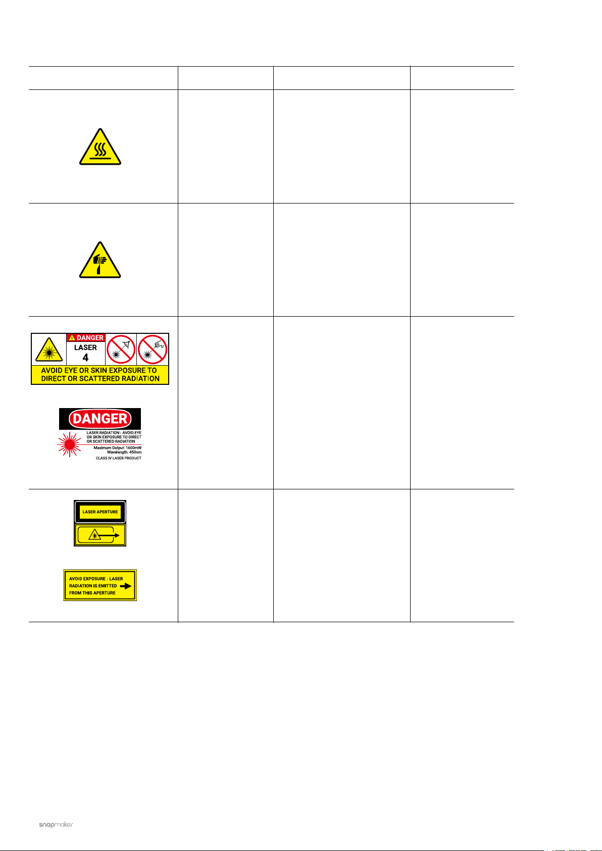
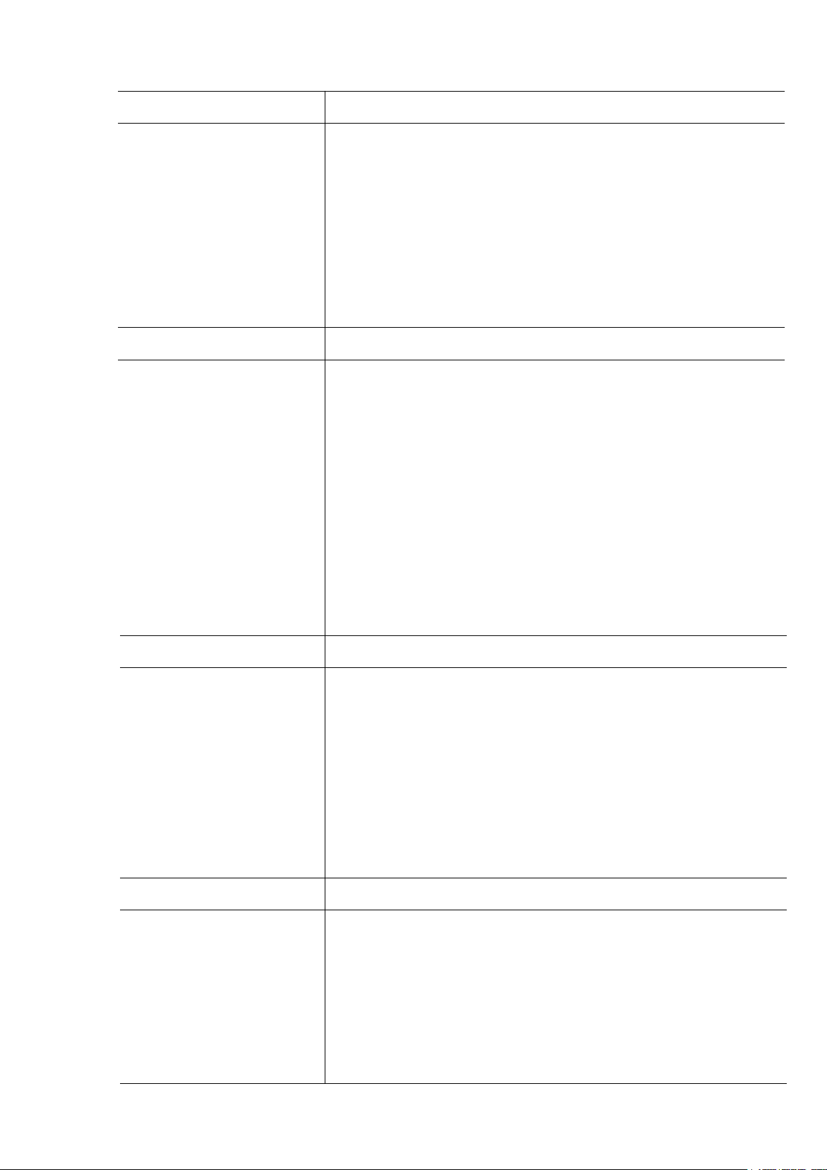
1.4 Labels on Your Snapmaker
Safety Labels Hazard Warning Location
IEC 60825
Hot surface
Sharp objects
Laser radiation
Avoid contact with hot
surface.
Take care to avoid injury
from sharp objects (e.g.
CNC Bits).
Class 4 laser product.
Avoid eyes and skin
exposure to direct or
scattered radiation.
On the 3D Printing
Module, Print Sheet
and Heated Bed
On the CNC Module
On the Laser Module
FDA
IEC 60825
FDA
Laser aperture
Laser radiation is emitted
On the Laser Module
from this aperture.
|
6
Page 13
1.5 Specifications
General
Frame Material
Connectivity
Touchscreen
Software
Supported File Types
Supported OS
Rated Power
3D Printing
Build Volume
Heated Bed Temperature
Layer Resolution
Nozzle Temperature
Nozzle Diameter
Supported Materials
Aluminum Alloys
Wi-Fi, USB Cable, USB Disk
5”TFT, Android System
Snapmaker Luban and third-party software
.stl, .obj, .svg, .jpeg, .png, more formats to be added
MacOS, Windows, Linux
320 W
A150: 160 x 160 x 145 mm
A250: 230 x 250 x 235 mm
A350: 320 x 350 x 330 mm
A150: Up to 110°C
A250: Up to 100°C
A350: Up to 80°C
50 - 300 microns
Up to 275°C
0.4 mm
PLA, ABS, TPU, Wooded PLA, etc.
Laser
Work Area
Laser
Wavelength
Safety Class
Supported Materials
CNC
Work Area
Shank Diameter
Spindle Speed
Supported Materials
A150: 160 x 160 mm
A250: 230 x 250 mm
A350: 320 x 350 mm
1,600 mW 450 nm Laser Diode
450 nm
Class 4
Wood, leather, plastic, fabric, paper, nontransparent acrylic, etc.
A150: 160 x 160 x 90 mm
A250: 230 x 250 x 180 mm
A350: 320 x 350 x 275 mm
0.5 mm - 6.35 mm (0.02 - 0.25 inches)
6,000 - 12,000 RPM
Wood, acrylic, PCB, carbon fiber sheet, jade, etc.
Note: Design and specifications are subject to change without notice.
Quick Start Guide | 7
Page 14
Before You Start
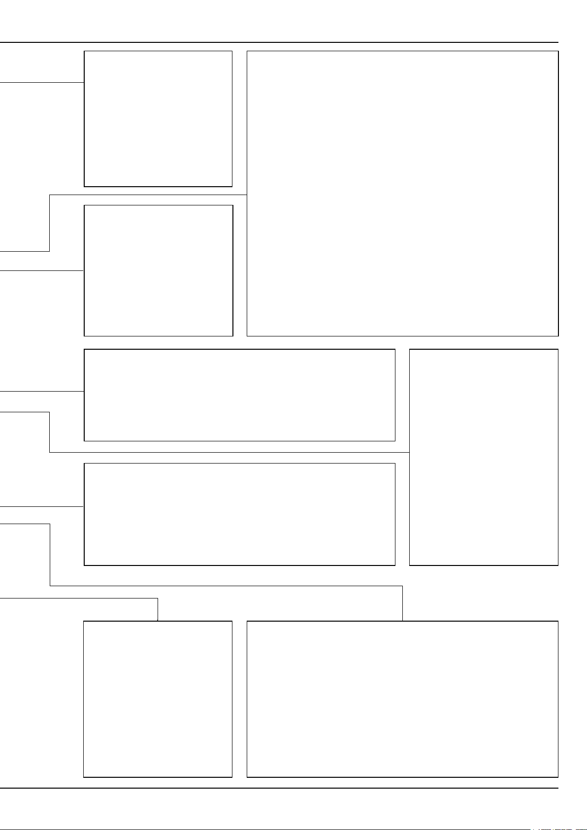
1.6 Parts List
Linear Module x 5
3D Printing Module x 1 Laser Module x 1 CNC Module x 1
Z-Axis Holder x 2Converter x 2
Heated Bed x 1
Print Sheet x 1
CNC Carving Platform x 1
Laser Engraving/Cutting Platform x 1
|
8
Platform x 1
Material Bag x 1
Page 15
| A250
QUICK START GUIDE
MAKE SOMETHING WONDERFUL
Quick Start Guide x 1
Power Module x 1
Laser Safety Goggles x 1
CNC Safety Goggles x 1
Fixture Accessory x 4
Arched Fixture x 4
Filament Holder Sheet x 1
Filament Holder Tube x 1 Tool Box x 1
USB Cable x 1
Touchscreen x 1
DC Power Cable x 1
AC Power Cable x 1
Touchscreen Holder x 1
Controller x 1
Filament x 1
Toolhead Cable x 1
Base Plate x 1
Z Conversion Cable x 1Y Conversion Cable x 1
Quick Start Guide | 9
Page 16
Before You Start
Tool Box
M4 x 30 Screw x 12
M4 x 70 Screw x 4
Divider x 6 Cable Holder x 1 Steel Strip Adjustor (For
Tweezers x 1
M4 x 10 Hex Socket
Head Screw x 17
Wing Nut x 4
M4 x 8 Screw x 68 M4 x 10 Hex Flat Head Screw
Foot x 4 + M4 x 10 Hex Socket
Head Screw x 4
Maintenance) x 1
Ball End Mill x 1Flat End Mill x 1
x 22
ER11 Collet (Only for 3.175 mm
CNC Bits) x 1 + ER11 Nut x 1
Hot End Kit x 1
Cable Tie x 1
Silicone Plug x 8
Diagonal Pliers x 1
USB Disk x 1
Palette Knife x 1
Material Bag
17mm Open-End Wrench x 1
14mm Open-End Wrench x 1
Screwdriver x 1
10
Wiping Cloth x 1CNC Material x 1 Laser Material x 2 Calibration Card x 2
|
Page 17
1.7 Video Tutorials
Apart from this Quick Start Guide, we also make video tutorials. Read this guide to finish assembly, and if you
are feeling adventurous, tricks that are not included in this guide can be found in the video tutorials. Visit our
website at https://support.snapmaker.com/hc/en-us-> select Snapmaker 2.0 -> Go to Video Tutorial.
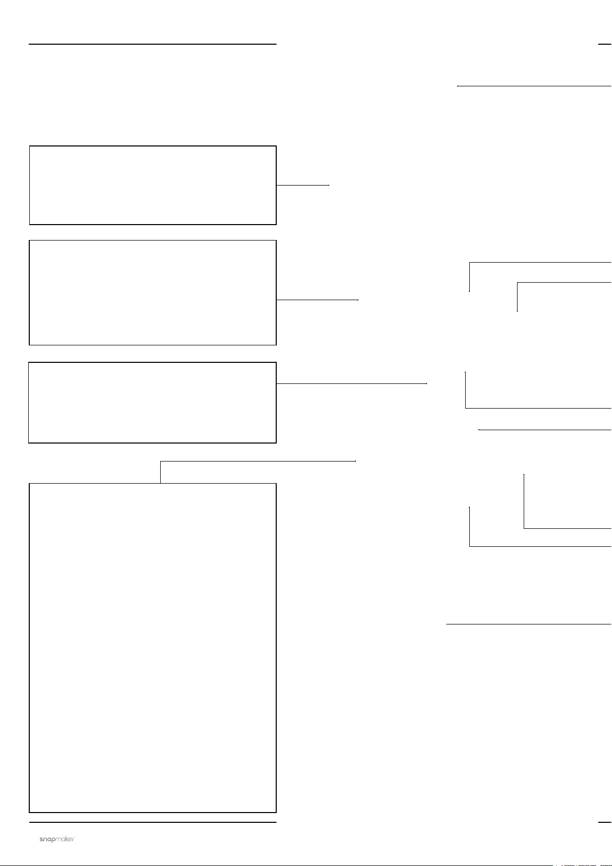
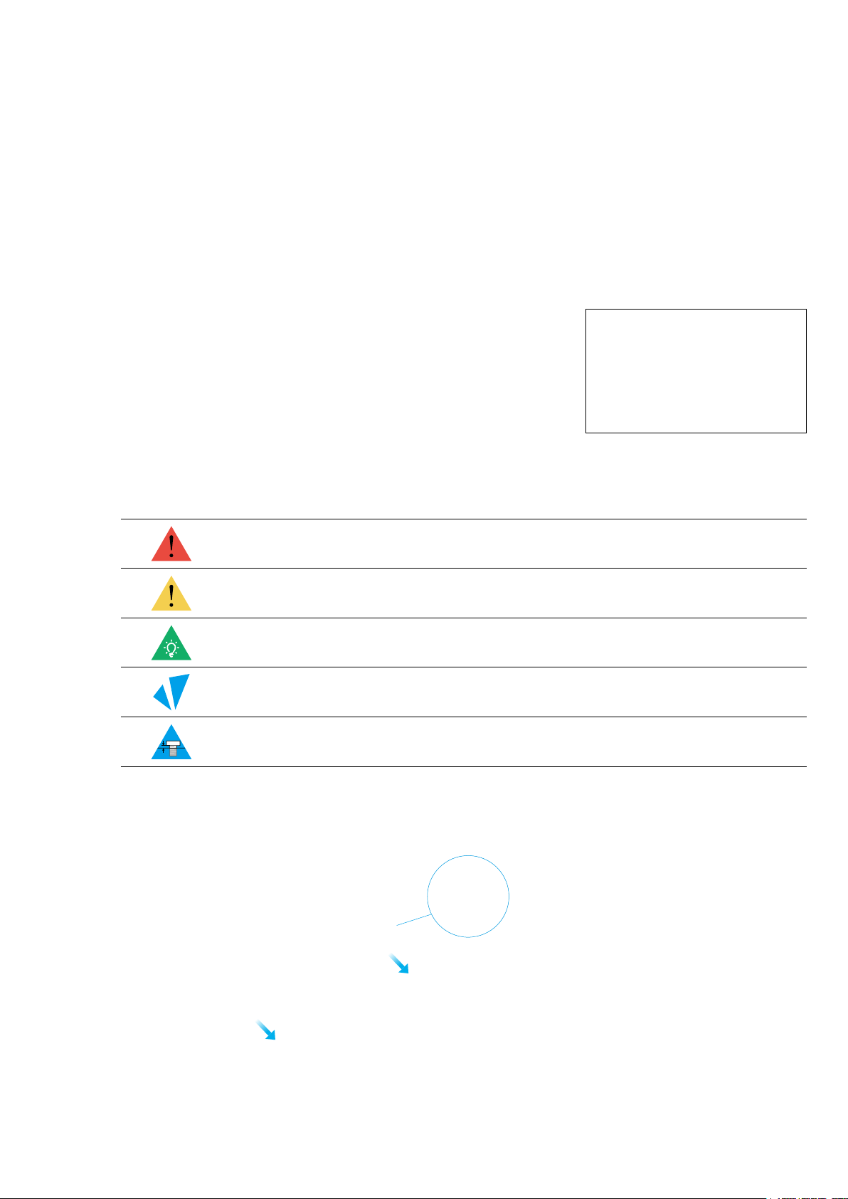
1.8 Used Symbols
CAUTION
NOTE
TIPS
Ignoring this type of message might result in malfunction or damage of the
machine and injuries to users.
Details you should be aware of throughout the process.
Tips offer you convenient operations and additional options.
Make sure that the highlighted part is facing the right way.
Do not tighten the screws when this symbol appears. Always tighten the
screws when it is absent.
1.9 Get the Screwdriver Ready
The screwdriver head H 2.5 is used for assembling the machine. The other heads are used for maintenance.
Make sure the screw head holder has been put back inside of the handle before use.
Quick Start Guide | 11
Page 18

Machine Assembly
12
|
Page 19

MACHINE
ASSEMBLY
Quick Start Guide | 13
Page 20
Machine Assembly
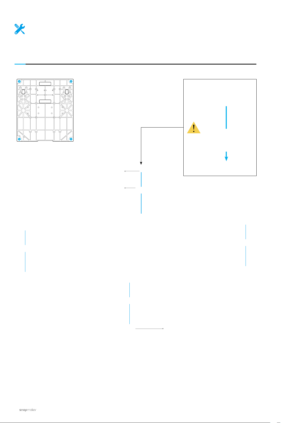
01
/22
Attach the feet to the Base Plate.
M4 x 10 Hex Socket Head
Screw x 4
Foot x 4
Base Plate x 1
14
|
Page 21
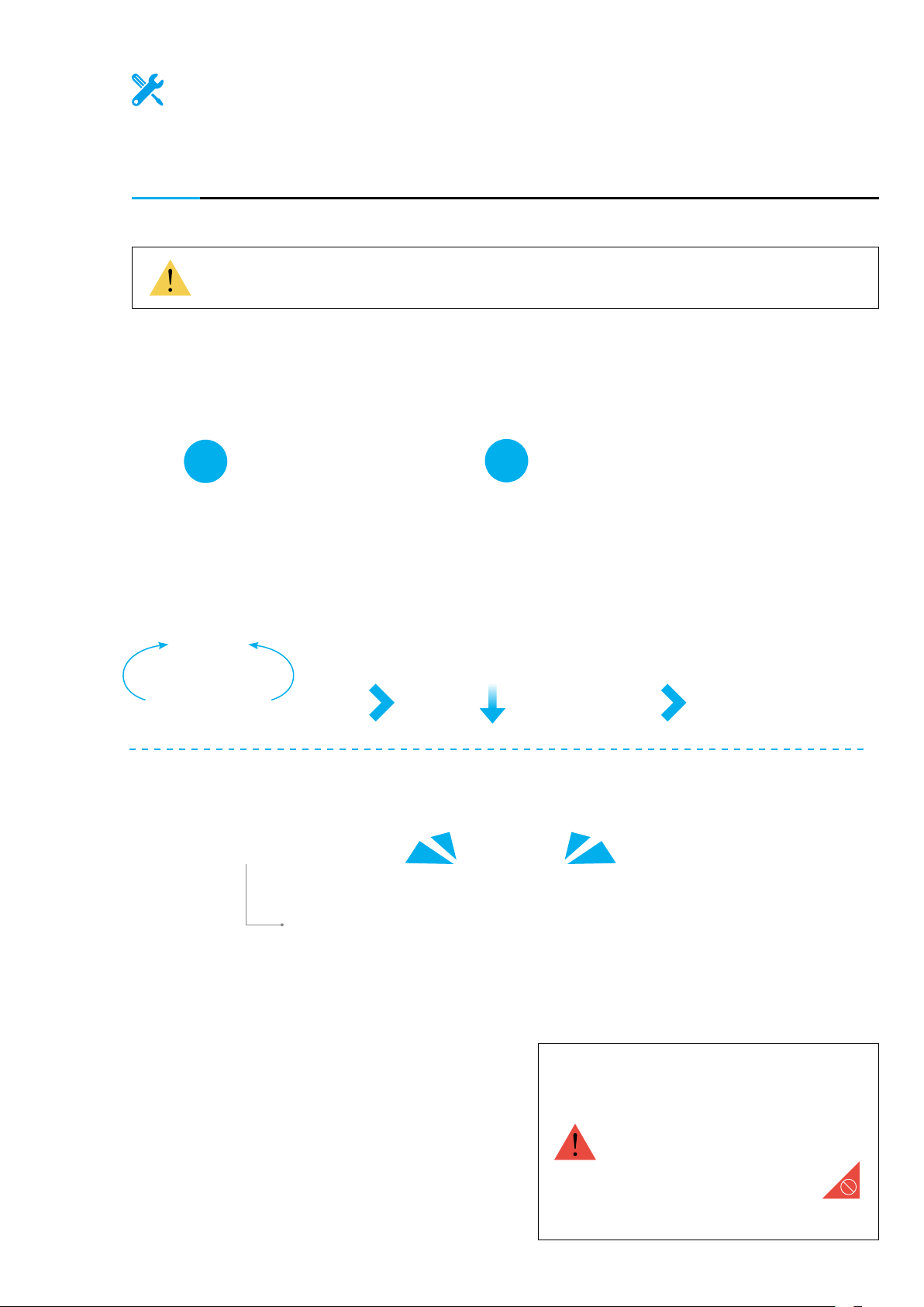
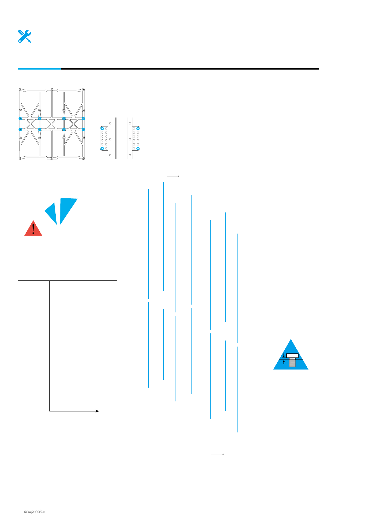
02
Make sure the sliders are aligning with each other. If not, you can move
them to the same position as illustrated.
/22
Hold the linear modules carefully to prevent them from falling.
1
2
DONE!
Linear Module x 2
Do not press the steel strip.
Quick Start Guide | 15
Page 22
Machine Assembly
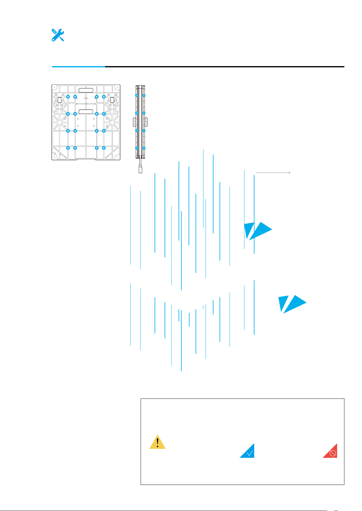
03
/22
Attach the Y axes to the Platform. Do not tighten the screws until Step 5.
M4 x 8 Screw x 8
Make sure to assemble the
Platform in correct orientation.
16
Platform x 1
|
Page 23
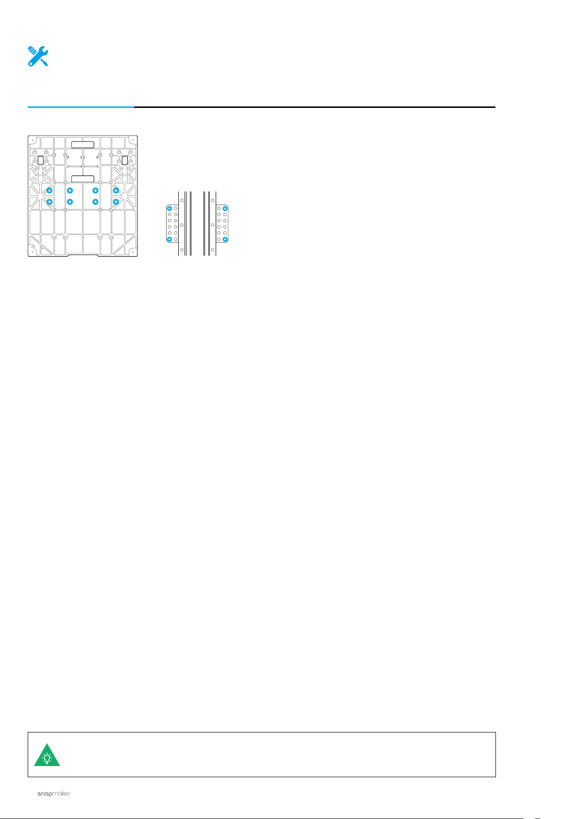
04
/22
Attach the Y axes to the Base Plate.
M4 x 8 Screw x 16
Make sure the Y-axis Linear Modules are accurately
mounted onto the grooves of the Base Plate.
Quick Start Guide | 17
Page 24
Machine Assembly
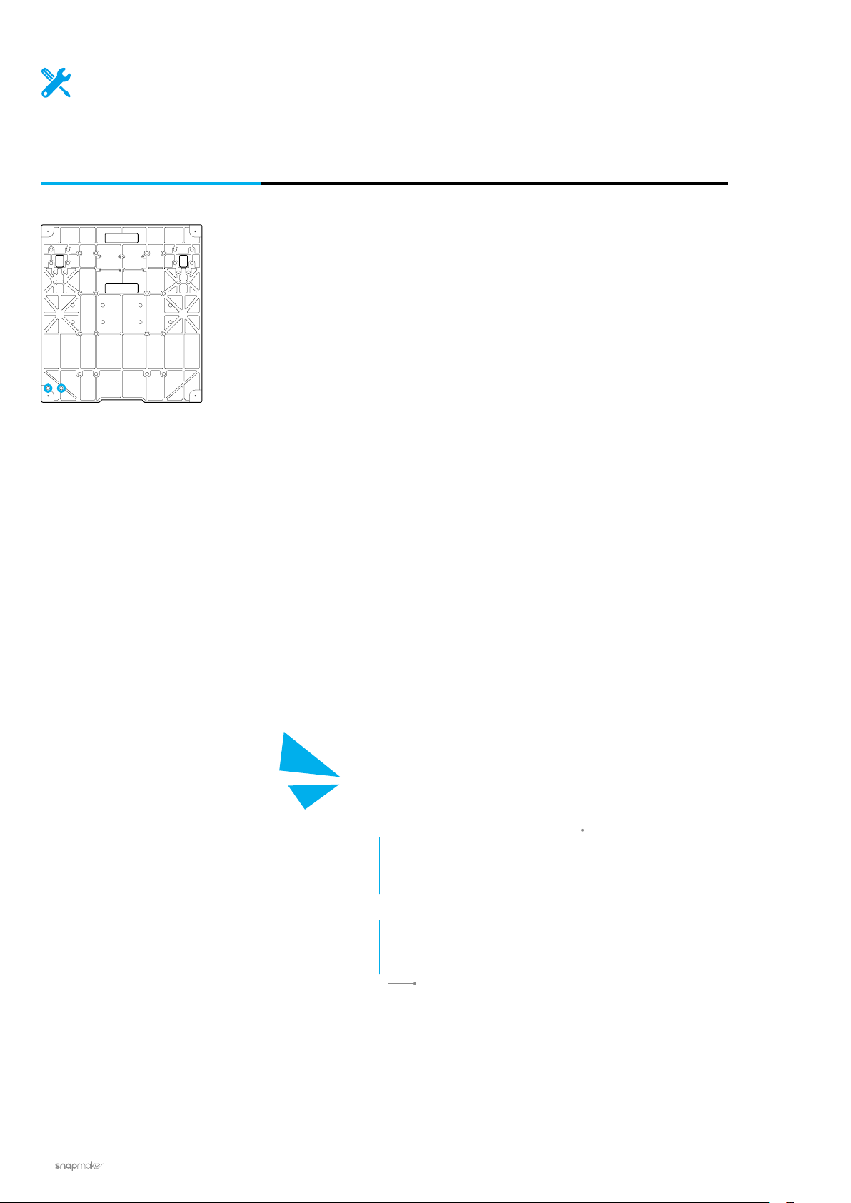
05
/22
Tighten the screws on the Y-axis sliders.
18
If the screws on the sliders are not aligning with the screw holes on the Base Plate, move the
Platform to the proper position.
|
Page 25

06
/22
Attach the Z-axis Holders to the Base Plate.
Z-axis Holder x 2
M4 x 8 Screw x 8
Quick Start Guide | 19
Page 26
Machine Assembly
07
/22
Attach the Touchscreen Holder to the Base Plate.
20
Touchscreen Holder x 1
M4 x 8 Screw x 2
|
Page 27
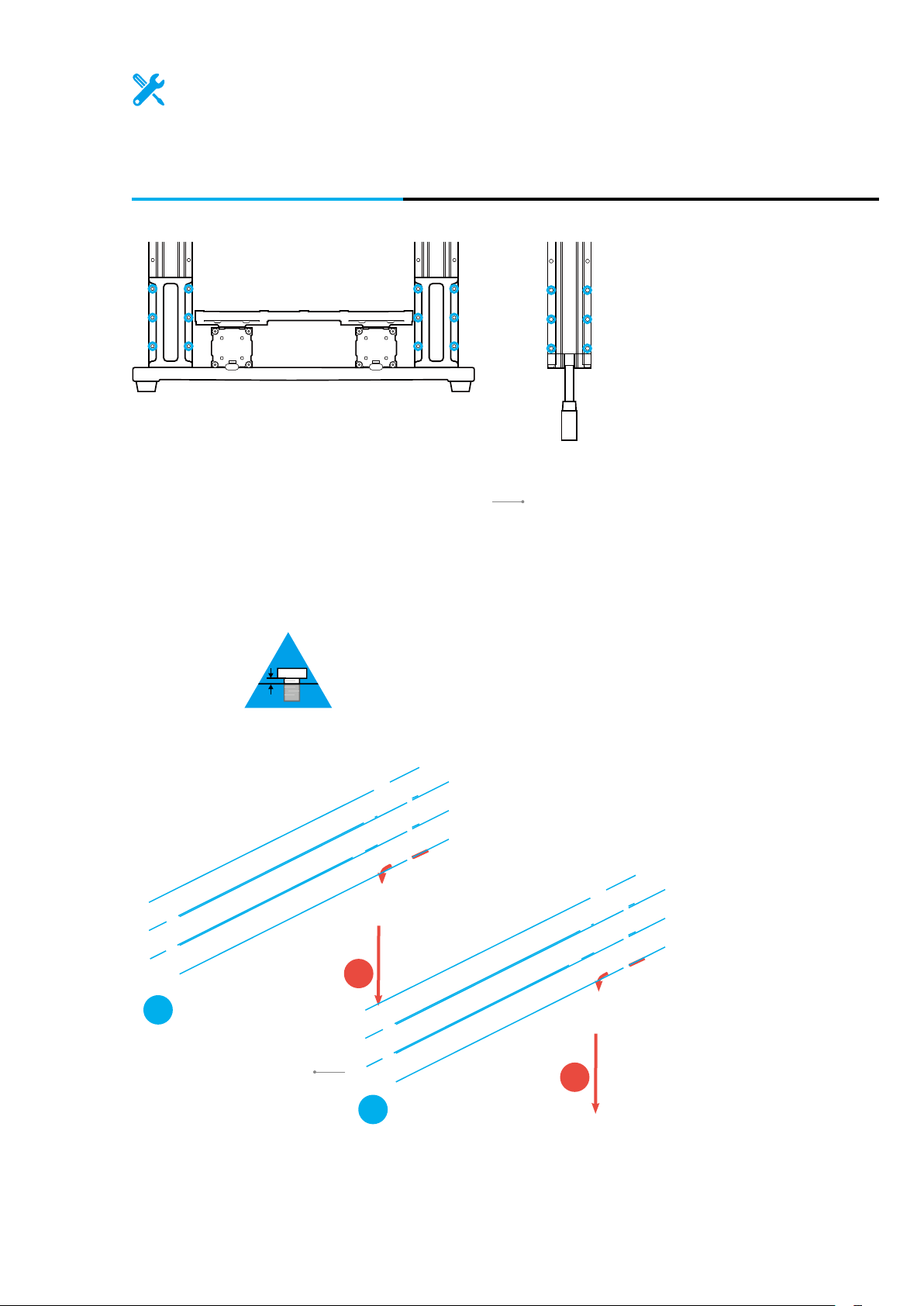
08
Thread the connecting cables through the holes of the holders, and then attach
the Z axes to the Z-axis Holders. Do not tighten the screws until Step 12.
/22
Linear Module x 2
2
M4 x 8 Screw x 12
1
1
2
Quick Start Guide | 21
Page 28
Machine Assembly
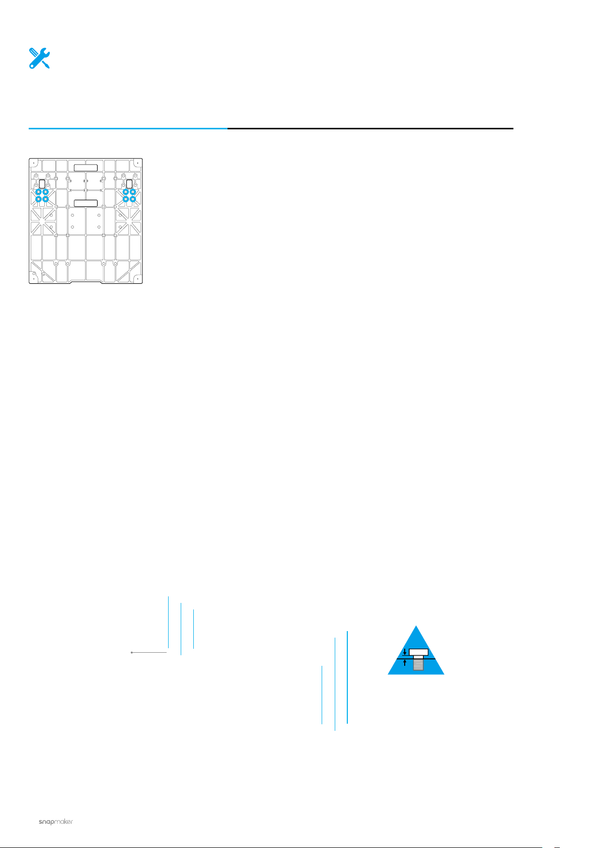
09
/22
Install the screws to the bottom of the Z axes. Do not tighten the screws
until Step 13.
M4 x 8 Screw x 8
|
22
Page 29
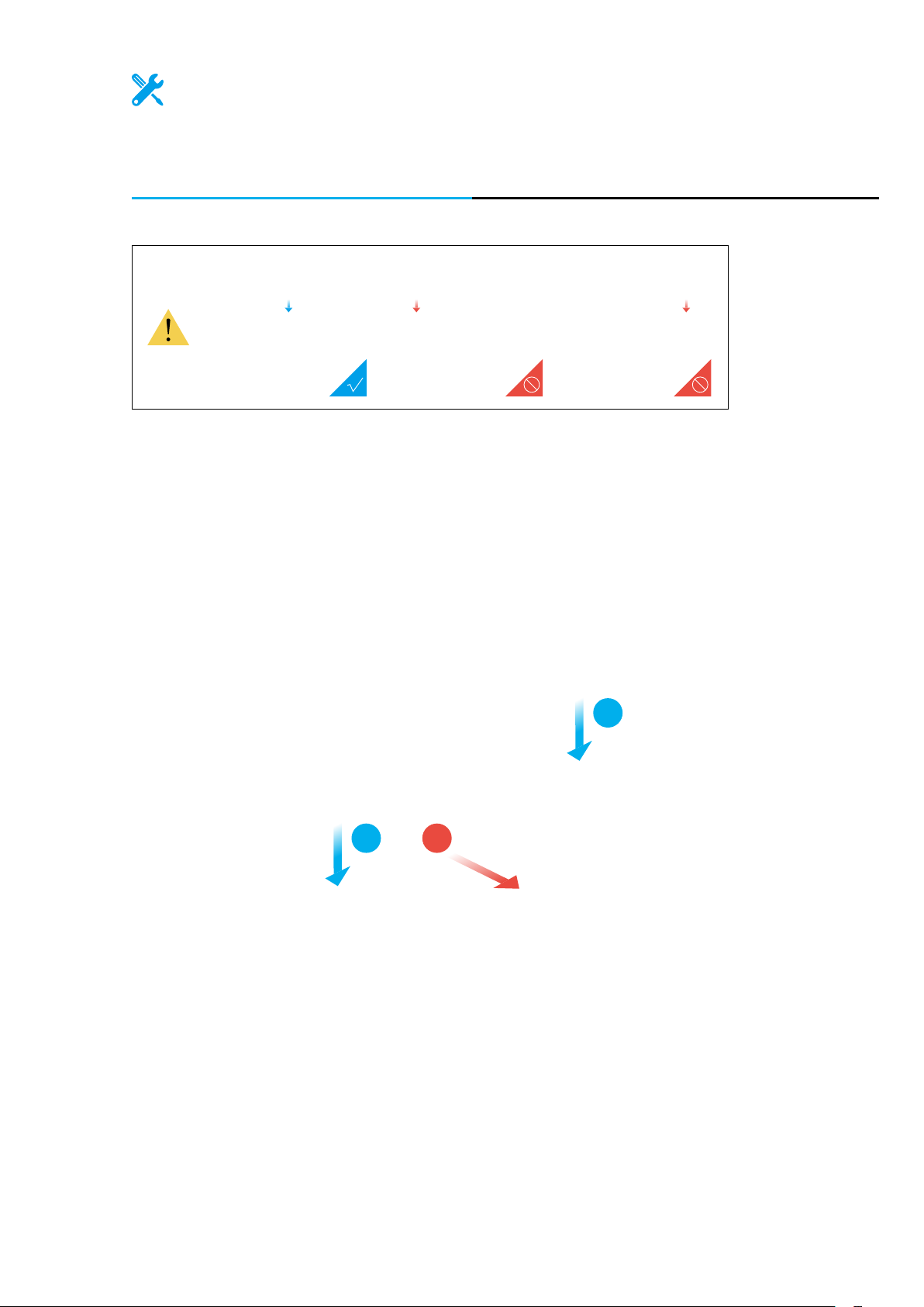
10
From the middle, move the Platform to the position as illustrated. Then move the
Z-axis sliders to the farthest end.
/22
2
12
Quick Start Guide | 23
Page 30
Machine Assembly
11
/22
Attach the X axis to the sliders on the Z axes.
Linear Module x 1
M4 x 8 Screw x 8
24
|
Page 31

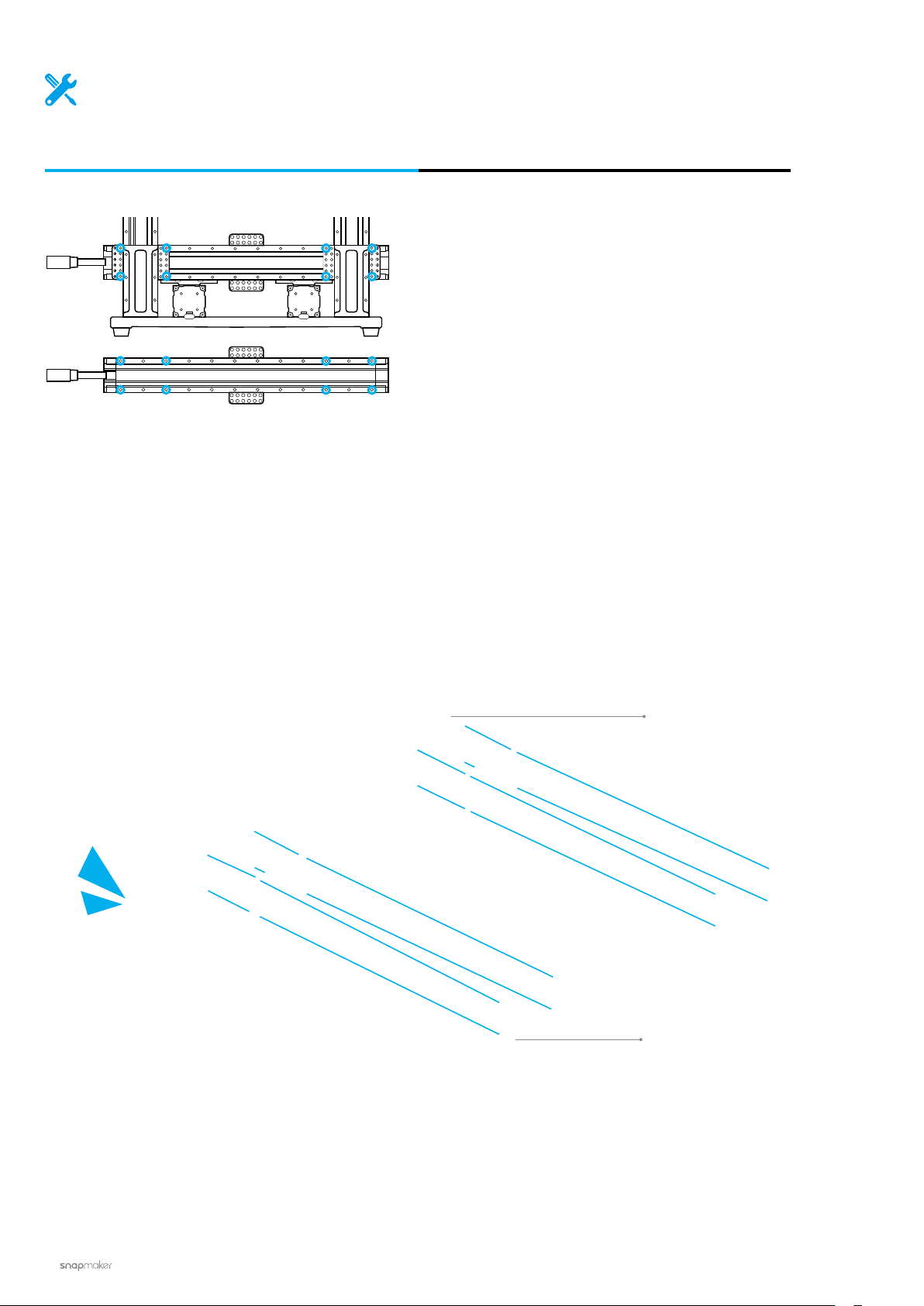
12
Tighten the screws that are used to attach the Z axes to the Z-axis Holders.
/22
Quick Start Guide | 25
Page 32

Machine Assembly
13
/22
Tighten the screws to the bottom of the Z axes.
26
|
Page 33

14
/22
Put your hands at each end of the linear module, and then move the X
axis to the top.
Make sure both ends of the linear module are in horizontal alignment with each other
throughout the process.
Quick Start Guide | 27
Page 34

Machine Assembly
15
/22
Locate the Y Conversion Cable, and the attached cable on both of the two
Y axes as illustrated. Connect them to the Converter.
Converter x 1
|
28
Y Conversion Cable x 1
Page 35

16
Attach the Y-axis Converter to the Base Plate.
/22
M4 x 30 Screw x 4
Quick Start Guide | 29
Page 36

Machine Assembly
17
/22
Locate the Z Conversion Cable, and the attached cable on both of the two
Z axes as illustrated. Connect them to the Converter.
30
Converter x 1
Z Conversion Cable x 1
|
Page 37

18
/22
Attach the Z-axis Converter to the Base Plate.
You can use the Cable Tie to organize the cables.
M4 x 30 Screw x 4
Quick Start Guide | 31
Page 38

Machine Assembly
19
/22
Attach the Controller to the Z axis.
32
Controller x 1
M4 x 30 Screw x 4
|
Page 39

20
/22
Open the dust plugs, and then connect the X, Y and Z axes with the Controller.
Toolhead Add-on 1 Add-on 2
X axis
Y axis
Z axis
Add-on 3 Heated Bed Power
Screen
USB
Make sure the connectors are in the right direction.
Keep the protective dust plugs
on the unplugged slots. Dust
accumulation may seriously
affect the performance of the
Controller.
Quick Start Guide | 33
Page 40

Machine Assembly
21
/22
Place the Touchscreen, and then connect the Touchscreen with the Controller.
Touchscreen x 1
|
34
Page 41

22
/22
Connect the cables for the Power Module.
Do not connect or disconnect any cables
when the machine is powered on.
Power Module x 1 AC Power Cable x 1DC Power Cable x 1
Make sure the power switch
is in the Off position.
Quick Start Guide | 35
Page 42

Machine Assembly
Absolutely amazing!
You have successfully assembled the
machine body. Now just select one function
to complete the assembly and bring your
first job into the world!
3D Printing
PAGE 38 PAGE 58 PAGE 74
|
36
Laser Engraving
and Cutting
CNC Carving
Page 43

Quick Start Guide | 37
Page 44

3D Printing
38
|
Page 45

3D Printing
3.1 Assembly
3.1.1 Assemble the 3D Printer
3.1.2 Initial Setup
3.2 Get Started
3.2.1 Calibrate the Bed
3.2.2 Load Filament
3.3 Start Printing
3.3.1 Prepare the G-code File
3.3.2 Start Your First Print
3.3.3 Remove the Print
Quick Start Guide | 39
Page 46

3D Printing
3.1.1 Assemble the 3D Printer
Guides & Pictures / Snapmaker
/07
Attach the 3D Printing Module to the slider on the X axis.
01
3D Printing Module x 1
M4 x 8 Screw x 4
40
Make sure the power switch
is in the Off position.
|
Page 47

/07
Connect the 3D Printing Module with the Controller.
02
Toolhead Cable x 1
Quick Start Guide | 41
Page 48

3D Printing
/07
03
Attach the Filament Holder to the Z axis.
M4 x 10 Hex Socket Head Screw x 1
Filament Holder Tube x 1
Filament Holder Sheet x 1
1:1
M4 x 10 Hex Socket Head
Screw x 2
42
|
Page 49

/07
04
Attach the Heated Bed to the Platform.
1:1
M4 x 10 Hex Flat Head Screw x 14
Heated Bed x 1
Quick Start Guide | 43
Page 50

3D Printing
/07
05
Place the Print Sheet.
Make sure the Heated Bed is contamination-free before you place the Print Sheet.
Make sure the Print Sheet aligns perfectly with the Heated Bed.
Print Sheet x 1
44
|
Page 51

/07
06
Connect the Heated Bed with the Controller.
Toolhead Add-on 1 Add-on 2
Add-on 3 Heated Bed Power
Heated Bed
Screen
USB
Quick Start Guide | 45
Page 52

3D Printing
/07
07
Attach the Cable Holder to the Z axis, and then lock the Toolhead Cable into place.
Cable Holder x 1
M4 x 8 Screw x 2
46
Make sure there is enough cable length
for the toolhead to move.
|
Page 53

3.1.2 Initial Setup
Guides & Pictures / Snapmaker
Plug the AC Power Cable into an electrical outlet. Switch the power on and follow the prompts on the
touchscreen: Read the Terms -> Name the Machine -> Connect to a Wi-Fi Network.
It is recommended to wait for 5 seconds after you restart your machine.
Skip this step if you have
completed the initial setup.
If you need to change the
settings above, swipe left
on the homepage of the
Touchscreen -> select
Settings -> tap Wi-Fi or
About Machine as needed.
The initial guide, which
helps you get started, will
appear only once. If you
need to launch it again,
swipe left on the homepage
of the Touchscreen -> select
Settings -> tap Guides.
Quick Start Guide | 47
Page 54

3D Printing
3.2.1 Calibrate the Bed
Guides & Pictures / Snapmaker
How It Works: Auto Leveling
The 3D Printing Module conducts a leveling procedure, with the sensor measuring the distance between the
nozzle and the Heated Bed at specific points. The movements of the extruder are adjusted to ensure that the
nozzle and the Heated Bed are at an optimum distance throughout the printing process.
How It Works: Adjusting the Z Offset
Z Oset is the distance between the tip of the nozzle and the print surface. Adjusting the Z Oset is the
process of tweaking the height of the nozzle by tiny increments. A proper Z Oset value helps ensure the
rst layer of your print sticks to the Print Sheet.
0.1 mm
Filament
Print Sheet
Too Low Too High
|
48
Page 55

How to Level
1. Run the Auto Leveling procedure on the touchscreen.
2. Place the Calibration Card or a piece of A4 paper between the nozzle and the Heated Bed, and manually
calibrate the Z Offset for the last point.
3. Keep adjusting the height of the nozzle using Up and Down buttons, until you feel slight resistance when you
pull out the Calibration Card, and it should be wrinkled when you push it forward. Tap Save to save the calibration
settings.
Slight Resistance
Wrinkled Calibration Card
Quick Start Guide | 49
Page 56

3D Printing
3.2.2 Load Filament
Guides & Pictures / Snapmaker
How It Works: Filament Loading
The motor drives the filament into the extruder, where the filament extrudes through the nozzle after being
heated by the heated block.
How to Load Filament
1. Hang the provided PLA filament over the Filament Holder. Cut the bending end of the filament using the
diagonal pliers, and then insert the filament into the 3D Printing Module.
|
50
Page 57

2. Tap Start on the Load Filament screen. After the temperature reaches the target temperature, tap Load and
then gently push the filament into the 3D printing module until you can feel the motor pulling the filament in.
You can change the target Nozzle Temp by sliding the scale bar.
3. Clean the nozzle using the tweezers, and tap Done.
If no filament is coming out of the nozzle, do not tap Done until you repeat the steps above
and the filament extrudes successfully.
Quick Start Guide | 51
Page 58

3D Printing
Congratulations!
You are now ready to print. Please continue to
generate the G-code file.
When you need to change the filament, select Controls and Nozzle. After the
temperature reaches the target temperature, tap Unload and pull the filament out
of the module.
52
|
Page 59

3.3.1 Prepare the G-code File
Guides & Pictures / Snapmaker
1. Install the Software and Complete the Initial Setup
Download our software the Snapmaker Luban at https://www.snapmaker.com/download and install. Then
connect to a Wi-Fi network: Enter the Workspace -> Connection -> Select Wi-Fi -> Click -> Select your
machine -> Click Open -> Tap Yes on the Touchscreen.
2. Generate the G-code File and Send It to the Machine
① Load the test le -> ② Use the default settings specically congured for the test le -> ③ Generate the
G-code le -> ④ Load G-code to Workspace -> ⑤ Send G-code to the machine via Wi-Fi.
You can also upload your own files by clicking Open File and configure the file settings. For
detailed instructions, refer to our online User Manual.
2
1
Files sent by Wi-Fi can be found on the Touchscreen: Files > Local.
2
3
4
5
You can also send the G-code files to the machine via the USB disk. Click Export G-code to file
in the Snapmaker Luban and save it to the USB disk. Then insert the USB disk into the Controller
and select Files > USB on the Touchscreen.
Quick Start Guide | 53
Page 60

3D Printing
3.3.2 Start Your First Print
Guides & Pictures / Snapmaker
After receiving the G-code file, tap Yes
and Start on the Touchscreen to start
printing. The first layer of the print
is key to print success. To prevent
damage we recommend that you keep
an eye on your print, especially while
the first layer is being laid out.
If you need to adjust
settings, you can either
tap Adjust Settings
prior to printing or swipe
left on the printing
progress screen.
If poor adhesion occurs, swipe left on the printing progress screen and try adjusting the Z Offset. Or you can
try leveling the Heated Bed again by selecting Calibration. Make sure the tip of the nozzle is clean before you
calibrate the bed.
54
|
Page 61

3.3.3 Remove the Print
Guides & Pictures / Snapmaker
Wait for the temperatures of the nozzle and the Heated Bed to drop to room temperature (displayed on the
Touchscreen) . Remove the Print Sheet from the Heated Bed and bend it slightly.
The nozzle and the Heated Bed are still extremely hot right after printing.
Quick Start Guide | 55
Page 62

3D Printing
Remove the Print Sheet from the Heated Bed, and place it down on a stable and flat surface.
You can also use the palette knife to remove the print.
The palette knife is sharp.
Share!
Share your prints in our
Facebook group and our
forum.
56
|
Page 63

Filament Runout Recovery & Power-Loss Recovery
Your printer supports filament runout recovery and power-loss recovery, so there is no need to worry about
resuming printing anymore! When the filament runs out, tapReady to Loadand load new filament to resume
printing. In case of power-loss, tapRecover to resume printing after the power has been restored.
Quick Start Guide | 57
Page 64

Laser Engraving and Cutting
58
|
Page 65

Laser Engraving
and Cutting
4.1 Assembly
4.1.1 Assemble the Laser Engraver and Cutter
4.1.2 Initial Setup
4.2 Get Started
4.2.1 Measure the Focal Length
4.2.2 Calibrate the Camera
4.2.3 Fasten the Material
4.3 Prepare the G-code File and Start Cutting
Quick Start Guide | 59
Page 66

Laser Engraving and Cutting
4.1.1 Assemble the Laser Engraver and Cutter
Guides & Pictures / Snapmaker
/04
Attach the Laser Module to the slider on the X axis.
01
Laser Module x 1
M4 x 8 Screw x 4
60
Make sure the power switch
is in the Off position.
|
Page 67

/04
02
Connect the Laser Module with the Controller.
Toolhead Cable x 1
Quick Start Guide | 61
Page 68

Laser Engraving and Cutting
/04
03
Attach the Laser Engraving/Cutting Platform to the Platform.
1:1
M4 x 10 Hex Socket Head Screw x 10
Laser Engraving/Cutting Platform x 1
62
|
Page 69

/04
04
Attach the Cable Holder to the Z axis, and then lock the Toolhead Cable into place.
Cable Holder x 1
M4 x 8 Screw x 2
Make sure there is enough cable length
for the toolhead to move.
Quick Start Guide | 63
Page 70

Laser Engraving and Cutting
4.1.2 Initial Setup
Guides & Pictures / Snapmaker
Plug the AC Power Cable into an electrical outlet. Switch the power on and follow the
prompts on the Touchscreen: Read the Terms -> Name the Machine -> Connect to a Wi-Fi
Network.
It is recommended to wait for 5 seconds after you restart your machine.
Skip this step if you have
completed the initial setup.
If you need to change the
settings above, swipe left
on the homepage of the
Touchscreen -> select
Settings -> tap Wi-Fi or
About Machine as needed.
The initial guide, which
helps you get started, will
appear only once. If you
need to launch it again,
swipe left on the homepage
of the Touchscreen -> select
Settings -> tap Guides.
64
|
Page 71

4.2.1 Measure the Focal Length
Guides & Pictures / Snapmaker
How It Works: Focal Point
The best focusing result can only be achieved when the Focal Point is right on the surface of the material
throughout engraving or cutting.
Perfect
Too Far
Too Close
How It Works: Focal Length
The machine engraves a few lines at different heights, and identifies optimal distance between the Laser
Module and the material surface. This optimal distance will be used as focal length. You only need to set the
thicknesses of different materials on the Touchscreen, and the machine will automatically adjust itself to
ensure that the focal length is consistent.
Quick Start Guide | 65
Page 72

Laser Engraving and Cutting
How It Works: Work Origin
Find out where the engraving/cutting will take place by setting the Work Origin. The Work Origin corresponds to
the (0, 0) coordinate origin in the software.
How to Measure the Focal Length
1. Place the provided material on the Laser Engraving/Cutting Platform. Secure it with the silicone plugs.
66
|
Page 73

2. Set the thickness of the material (1.5 mm) and tap Save.
3. Tap X-, X+, Y-, Y+, Z-, or Z+ to move the Laser Module. After the laser camera shade has slightly touched the
surface of the material, tap Next. Put on the Laser Safety Goggles before setting the Work Origin.
Quick Start Guide | 67
Page 74

Laser Engraving and Cutting
4. Tap X-, X+, Y-, or Y+ to move the laser spot to where the Work Origin will be, and then tap Set Work Origin
and Run Boundary to check if the work origin is proper. If not, reset the Work Origin and run boundary again.
If the Laser Module runs into any portions of the machine, turn off the machine immediately.
5. Tap Start, and the machine will auto focus.
Should you need to remeasure the focal length, refer to our online User Manual for detailed
instructions.
68
|
Page 75

4.2.2 Calibrate the Camera
Guides & Pictures / Snapmaker
1. Remove the engraved material. Place a piece of blank white paper (no less than 150 mm x 150 mm) on the
center of the Laser Engraving/Cutting Platform, and fasten it.
2. Tap Start, and the machine will use the engraved square to calibrate the camera.
If you have detached the Laser Module from the X axis, or if you have reassembled the
machine, please recalibrate the camera: Swipe left on the homepage of the Touchscreen ->
select Settings -> tap Laser -> tap Camera Calibration.
Quick Start Guide | 69
Page 76

Laser Engraving and Cutting
4.2.3 Fasten the Material
Guides & Pictures / Snapmaker
Remove the engraved paper, and then fasten another provided material on the center of the Laser Engraving/
Cutting Platform.
You can also fasten materials using other tools.
If you need to fasten thick materials, refer to 5.2.1 Fasten the Material.
Make sure the clamp set will not collide with any portions of the machine.
70
|
Page 77

4.3 Prepare the G-code File and Start Cutting
Guides & Pictures / Snapmaker
1. Download our software the Snapmaker Luban at https://www.snapmaker.com/download and install. Then
connect to a Wi-Fi network: Enter the Workspace -> Connection -> Select Wi-Fi -> Click -> Select your
machine -> Click Open -> Tap Yes on the Touchscreen.
2. Click Camera Capture in the Laser G-code Generator and then click Start. Wait for the machine to take
photos and stitch them into a panorama of the platform, and click Confirm.
Quick Start Guide | 71
Page 78

Laser Engraving and Cutting
If the edges of the captured image are not aligned, click Calibration to manually calibrate the
camera.
Zoom into the image and move the lines until they perfectly match the square, click Confirm ->
Apply to see the finished image.
72
Click Confirm and the finished image will be loaded into the quadrant in the coordinate system.
You can repeat the steps above if the edges of the captured image are still not aligned.
|
Page 79

3. ① Open the test le from
captured platform -> ③ Click
default settings specically congured for the test le -> ⑤ Generate the G-code le -> ⑥ Load G-code to
Case Library
Process
after conguring the settings in
-> ② Drag the image to where the cutting will take place on the
Configurations
section -> ④ Use the
Workspace
-> ⑦ Set the thickness of the material -> ⑧ Click
You can also upload your own files by clicking Open File in Editor and configure the file settings.
2
Run
.
3
1
8
4
5
6
7
You can also start engraving/cutting by using the USB disk, connecting with the USB cable, or
sending G-code files via Wi-Fi, in which case you will need to set the work origin yourself. For
detailed instructions, refer to our online User Manual.
4. Remove the finished work and complete the assembly.
Share!
Share your finished work
in our Facebook group and
our forum.
Quick Start Guide | 73
Page 80

CNC Carving
74
|
Page 81

CNC Carving
5.1 Assembly
5.1.1 Assemble the CNC Carver
5.1.2 Initial Setup
5.2 Get Started
5.2.1 Fasten the Material
5.2.2 Attach the Bit
5.3 Start Carving
5.3.1 Prepare the G-code File
5.3.2 Set the Work Origin and Start Carving
5.3.3 Clean the Finished Work
Quick Start Guide | 75
Page 82

CNC Carving
5.1.1 Assemble the CNC Carver
Guides & Pictures / Snapmaker
/04
Attach the CNC Module to the slider on the X axis.
01
CNC Module x 1 M4 x 8 Screw x 4
76
Make sure the power switch
is in the Off position.
|
Page 83

/04
Connect the CNC Module with the Controller.
02
Toolhead Cable x 1
Quick Start Guide | 77
Page 84

CNC Carving
/04
03
Attach the CNC Carving Platform to the Platform.
1:1
M4 x 10 Hex Socket Head Screw x 14
78
CNC Carving Platform x 1
|
Page 85

/04
04
Attach the Cable Holder to the Z axis, and then lock the Toolhead Cable into place.
Cable Holder x 1
M4 x 8 Screw x 2
Make sure there is enough cable length
for the toolhead to move.
Quick Start Guide | 79
Page 86

CNC Carving
5.1.2 Initial Setup
Guides & Pictures / Snapmaker
Plug the AC Power Cable into an electrical outlet. Switch the power on and follow the prompts on the
Touchscreen: Read the Terms -> Name the Machine -> Connect to a Wi-Fi Network.
It is recommended to wait for 5 seconds after you restart your machine.
Skip this step if you have
completed the initial setup.
If you need to change the
settings above, swipe left
on the homepage of the
Touchscreen -> select
Settings -> tap Wi-Fi or
About Machine as needed.
The initial guide, which
helps you get started, will
appear only once. If you
need to launch it again,
swipe left on the homepage
of the Touchscreen -> select
Settings -> tap Guides.
80
|
Page 87

5.2.1 Fasten the Material
Guides & Pictures / Snapmaker
1. Place the provided material on the center of the CNC Carving Platform.
2.Attach the clamp set to the CNC Carving Platform, and then fix the material by screwing the wing nuts.
The size of our provided model is 139.2 x 141.5 mm. Make sure the clamp set does not impede
the movement of the CNC Bit.
M4 x 70 Screw
Wing Nut
Fixture Accessory
Arched Fixture
Quick Start Guide | 81
Page 88

CNC Carving
Do not screw the screws all the way down through the CNC Carving Platform.
Make sure the clamp set will not collide with any portions of the machine.
82
All the three slots as illustrated can be used to fasten the material.
|
Page 89

5.2.2 Attach the CNC Bit
Guides & Pictures / Snapmaker
How It Works: CNC Bit Usage
Flat End Mill is typically used for slotting or cutting materials into flat surface.
Ball End Mill is typically used for carving materials into curved surface.
How to Attach the CNC Bit
1. Obliquely insert the ER11 collet into the ER11 nut until it clicks into place.
ER11 Nut
ER11 Collet (The Provided Collet is Only for
3.175 mm CNC Bits)
Quick Start Guide | 83
Page 90

CNC Carving
2. Put on the CNC Safety Goggles. Insert the CNC Bit into the ER11 collet (Flat End Mill is required for our
provided model). Keep pushing the CNC Bit until its end bottoms against the shell of the ER11 collet.
Handle the CNC Bits carefully and keep them out of reach of children.
3. Twist the entire unit onto the shank as tight as possible, and then completely tighten the ER11 nut using the
open-end wrenches.
84
14 mm Open-End Wrench 17 mm Open-End Wrench
Congratulations!
You are now ready to print. Please continue to
generate the G-code file.
|
Page 91

5.3.1 Prepare the G-code File
Guides & Pictures / Snapmaker
1. Install the Software and Complete the Initial Setup
Download our software the Snapmaker Luban at https://www.snapmaker.com/download and install. Then
connect to a Wi-Fi network: Enter the Workspace -> Connection -> Select Wi-Fi -> Click -> Select your
machine -> Click Open -> Tap Yes on the Touchscreen.
2. Generate the G-code File and Send It to the Machine
① Open the test le from
section -> ③ Use the default settings specically congured for the test le -> ④ Generate the G-code le ->
⑤ Load G-code to
Workspace
Case Library
-> ⑥ Send G-code to the machine via Wi-Fi.
-> ② Click
Process
after conguring the settings in
Configurations
You can also upload your own files by clicking Open File in Editor and configure the file settings.
2
1
3
4
5
Files sent by Wi-Fi can be found on the Touchscreen: Files > Local.
You can also send the G-code files to the machine via the USB disk. Click Export G-code to
file in the Snapmaker Luban and save it to the USB disk, and then insert the USB disk into
the Controller and select Files > USB on the Touchscreen.
Quick Start Guide | 85
6
Page 92

CNC Carving
5.3.2 Set the Work Origin and Start Carving
Guides & Pictures / Snapmaker
How It Works: Work Origin
Find out where the carving will take place by setting the Work Origin. The Work Origin corresponds to the (0, 0)
coordinate origin in the software.
86
|
Page 93

How to Set the Work Origin
1. After receiving the G-code file, tap Yes and Next on the Touchscreen to enter the Set Work Origin screen.
If you need to adjust settings, you can either tap Adjust Settings on the Preview screen or
swipe left on the carving progress screen.
2. Tap X-, X+, Y-, Y+, Z-, or Z+ to move the CNC Bit to where the Work Origin will be (In this case, we set the
center of the image as the coordinate origin in the software). Now the CNC Bit should be about 5 mm away
from the material.
5 mm
Quick Start Guide | 87
Page 94

CNC Carving
3. Place the Calibration Card or a piece of A4 paper between the CNC Bit and the material. Keep adjusting the
height of the CNC Bit using Z- or Z+ buttons until you feel slight resistance when you pull out the Calibration
Card, and it should be wrinkled when you push it forward. Tap Set Work Origin.
Slight Resistance
0.1 mm
Wrinkled Calibration Card
4. Tap Z+ to lift the CNC Bit until it is above the clamp set, and then tap Run Boundary to check if the Work
Origin is proper. If any part of the boundary trailed by the CNC Bit goes outside of the material, or if the CNC Bit
runs into any portions of the machine, reset the Work Origin and run boundary again.
If you have run boundary with the CNC Bit above the clamp set, you can lower the CNC bit to
run boundary again.
If the CNC bit runs into any portions of the machine, power off the machine immediately and
check if the CNC Bit is damaged. If so, change the CNC Bit.
5. Tap Start to start carving.
|
88
Page 95

5.3.3 Clean the Finished Work and the Machine
Guides & Pictures / Snapmaker
1. Remove the clamp set from the CNC Carving Platform.
2. Clean the finished work and the machine with a dust collector, and then remove the finished work using the
diagonal pliers.
Quick Start Guide | 89
Page 96

CNC Carving
Share!
Share your finished work
in our Facebook group and
our forum.
90
|
Page 97

Resources
This guide is subject to change. The latest version is on our Support website: Select
Snapmaker 2.0 -> Go to Quick Start Guide.
https://support.snapmaker.com/hc/en-us
Besides this guide, a User Manual is available on our Support website: Select Snapmaker 2.0
-> Go to User Manual.
https://support.snapmaker.com/hc/en-us
We are here for you whenever you need general information or technical support:
support@snapmaker.com.
For any sales inquiries:
sales@snapmaker.com.
For product purchases:
https://shop.snapmaker.com.
Share anything you want with other Snapmaker users in our forum:
https://forum.snapmaker.com.
Quick Start Guide | 91
Page 98

 Loading...