

SMSC LAN83C175 Datasheet

LAN83C175
ADVANCE INFORMATION
LAN83C175 - EPIC/C
Ethernet CARDBUS Integrated Controller With
Modem Support
FEATURES
• IEEE 802.3 Compliant 10/100 Mb/s
Ethernet Controller
• Fully Compliant Glueless Integrated
CardBus Interface
• Secondary 8 Bit interface to Support Multifunction CardBus Adpaters Including LAN /
Rockwell or Lucent Modem Combinations
• Supports 3.3V or 5V Modem and Physical
Layer Interface
• 10Base-T Physical Layer Digital Support
- Smart Squelch Digital Noise Filter and
Receive and Collision Input to Reject
Both Analog and Digital Noise on
Twisted Pair Receive Inputs
- 10Mbps Manchester Encoding /
Decoding with Receive Clock
Recovery
- Automatic Polarity Detection
- Full Duplex Support
• Scatter/Gather DMA Capability
• Supports Chaining of Transmit Packets
• Optional Early Transmit and Early Receive
• Optional Receive Lookahead Buffering
Mode
• 4.5Kbyte On-Chip Receive Buffer and
1.5Kbyte On-Chip Transmit Buffer
Eliminate Bus Latency Issues
• Automatic Rejection of Runt Packets
• Automatic Retransmission of Collision
Frames from Internal Buffer
• Automatic Padding of Short Frames
• Big or Little Endian Byte Ordering
• Capable of Supporting 64Kbyte Expansion
Boot ROM
• IEEE Standard MII Interface to Physical
Layer
• Interface to LAN83C694 Shares MII Pins
• Serial MII Management Interface
• Interface to an 8 Bit Parallel EEPROM for
Storage and Retrieval of LAN Address and
Configuration Information
• On-Chip Clock Multiplier
• Low Power Sleep Mode and Extended
Power Management Features
• Internal and External Loopback Diagnostic
Functions
• Simple I/O Pin Mapping Scheme to
Facilitate In-Circuit Test
• Single 3.3V Supply
• 208 Pin TQFP Package

2
TABLE OF CONTENTS
FEATURES........................................................................................................................................1
GENERAL DESCRIPTION .................................................................................................................3
PIN CONFIGURATION.......................................................................................................................5
DESCRIPTION OF PIN FUNCTIONS .................................................................................................6
FUNCTIONAL DESCRIPTION............................................................................................................9
DMA OPERATION............................................................................................................................11
TRANSMIT DMA ..............................................................................................................................11
RECEIVE DMA.................................................................................................................................17
TRANSMIT/RECEIVE ARBITRATION FOR CARDBUS BUS...............................................................25
BIG/LITTLE ENDIAN SUPPORT....................................................................................................... 25
MAC OPERATION................................................................................................................................ 28
MAC RECEIVER..................................................................................................................................28
MAC TRANSMITTER........................................................................................................................30
MII MANAGEMENT INTERFACE ......................................................................................................32
EEPROM INTERFACE..................................................................................................................... 32
POWER DOWN MODE....................................................................................................................34
JUMPER OPTIONS..........................................................................................................................34
SOFT RESET...................................................................................................................................34
CONFIGURATION ...........................................................................................................................35
MAPPING OF ROM AND CONTROL FUNCTIONS.........................................................................................35
REGISTER MAP/CONTROL REGISTER DECODE..........................................................................................37
REGISTER DESCRIPTIONS/CONTROL REGISTERS .....................................................................38
MODEM AND EXTERNAL FLASH RAM INTERFACE AND CONTROL...........................................64
MODEM REGISTERS MAP .............................................................................................................64
MODEM REGISTERS BITS DESCRIPTION...................................................................................................65
PHYSICAL CONNECTION........................................................................................................................68
MODEM AND RAM ACCESS TIMING.........................................................................................................68
OPERATIONAL DESCRIPTION....................................................................................................... 69
MAXIMUM GUARANTEED RATINGS........................................................................................................... 69
DC ELECTRICAL CHARACTERISTICS........................................................................................................ 69
TIMING DIAGRAMS ........................................................................................................................71
80 Arkay Drive
Hauppauge, NY. 11788
(516) 435-6000
FAX (516) 273-3123

3
GENERAL DESCRIPTION
The LAN83C175 EPIC/C is a high-performance
Low CPU Utilization Ethernet network controller
designed to interface directly to the CardBus
Local Bus on one side and to the 802.3 standard
Media Independent Interface (MII) on the other
side. The network interface can also be
configured to communicate directly with the
LAN83C694 10BASE-T transceiver.
The LAN83C175 implements 802.3 Media
Access Control functions. It is capable of
running at Ethernet rates of both 100Mbps and
10Mbps. An MII compliant serial management
interface is provided to control external media
dependent transceivers. The LAN83C175 is a
two channel bus master (one for transmit, one
for receive) capable of transferring data at the
maximum CardBus transfer rate of 132Mbps.
The LAN83C175 has several features designed
to maximize throughput and minimize CPU
utilization, including the optional Receive
Lookahead Buffering Mode, which eliminates the
need to re-copy the data from one host memory
location to another.
The LAN83C175 also includes a secondary
general purpose 8-bit interface with appropriate
registers, address lines and control lines. This
secondary interface provides all of the signals
required to implement a secondary function on
a CardBus adpater. An example of such a
secondary function is a 33.6Kbps or higher
speed modem design based on a Rockewell or
Lucent modem chip set.

4
Cardbus
Epic/C
Cardbus
Interface
RINGIN
RINGOUT
MPWRDWN
MRESET_N
MCS_N
MA(15:0)
MD(7:0)
MA(x:0)
RDYMRDYM
AUDIOAUDIOIN
RINGIN
RINGOUT
PWRDWN
HINTIREQM
~RESET
~HCS
HA(x:0)
HD(7:0)
WR_N
RD_N
RAMCS_N
Physical Layer
Interface
PHY
FIGURE 1 - LAN83C175 SYSTEM DIAGRAM
~HWT
~HRD
Modem
ADDR(15:0)
DATA(7:0)
RAMWE_N
RAMOE_N
RAMCS_N
RAM

5
PIN CONFIGURATION
5354555657585960616263646566676869707172737475767778798081828384858687888990919293949596979899
100
101
102
103
104
VDD
3.3
GND
N/C
AUDIOOUT
VDD
3.3
CAD24
nCBE3
GND
CAD23
CAD22
CAD21
VDD
3.3
CAD20
CAD19
GND
CAD18
CAD17
GND
CAD16
nCBE2
VDD
3.3
nCFRAME
nCIRDY
GND
N/C
nCTRDY
nCDEVSEL
VDD
3.3
nCSTOP
nCBLOCK
GND
nCPERR
nCSERR
VDD
3.3
CPAR
nCBE1
GND
VDD
3.3
CAD15
CAD14
GND
CAD13
CAD12
VDD
3.3
CAD11
N/C
GND
CAD10
CAD9
CAD8
VDD
3.3
GND
208
207
206
205
204
203
202
201
200
199
198
197
196
195
194
193
192
191
190
189
188
187
186
185
184
183
182
181
180
179
178
177
176
175
174
173
172
171
170
169
168
167
166
165
164
163
162
161
160
159
158
157
VDD
PHY
GND
RX_CLK
VDD
3.3
RX_DV
RX_ER
MDATA
GND
MCLK
PHYRST
TX_EN
GND
TXD3
TXD2
GND
TXD1
TXD0
VDDPHY
GND
RXD3
RXD2
VDD
PHY
RXD1
RXD0
CRS
N/C
N/C
FETPWRM
POWERDWNM
nRESETM
RINGOUT
nROMCS
nCSM
N/C
VDD
3.3
nMEMRD
nMEMWR
VDD
MOD
RINGIN
AUDIOIN
IREQM
GND
RDYM
MD7
MD6
GND
MD5
MD4
MD3
MD2/JMP2
GND
VDD
MOD
PHY
VDD
TX_CLK
FETPWR_PHY
ZENER
CLK25IN
nPHY_PWRDWN
694nEN
VDD
694nLNK
CBCLK
nCCLKRUN
nCGNT
nCREQ
CAD31
CAD30
CAD29
CAD28
CAD27
CAD26
CAD25
STATCHG
GND
COL
GND
VDD
VDD
BIAS
GND
GND
TEST
GPIO1
GPIO2
VDD
GND
GND
nCINT
nRST
GND
VDD
GND
VDD
GND
VDD
GND
VDD
GND
VDD
GND
1
2
N/C
3
4
5
6
7
X20
8
3.3
9
3.3
10
11
12
13
14
15
16
17
PHY
18
19
20
21
22
N/C
23
3.3
24
25
26
27
28
29
30
3.3
31
32
33
34
35
3.3
36
N/C
37
38
39
40
3.3
41
42
43
44
45
3.3
46
47
48
49
50
3.3
51
52
LAN83C175
208 Pin TQFP
156
155
154
153
152
151
150
149
148
147
146
145
144
143
142
141
140
139
138
137
136
135
134
133
132
131
130
129
128
127
126
125
124
123
122
121
120
119
118
117
116
115
114
113
112
111
110
109
108
107
106
105
MOD
VDD
GND
N/C
MD1/JMP1
MD0/JMP0
MA15
MA14
N/C
MA13
MA12
3.3
VDD
MA11
GND
MA10
MOD
VDD
MA9
MOD
VDD
MA8
GND
MA7
MA6
GND
MA5
MA4
GND
MA3
MA2
MA1
MA0
N/C
GND
3.3
VDD
GND
N/C
3.3
VDD
CAD0
CAD1
GND
CAD2
CAD3
GND
3.3
VDD
CAD4
CAD5
GND
CAD6
N/C
3.3
VDD
CAD7
nCBE0
GND
3.3
VDD

6
DESCRIPTION OF PIN FUNCTIONS
TQFP PIN NO. NAME I/O DESCRIPTION
30 CBCLK I
28 nRST I
39,40,42,44,45,47,48,58
CAD[31:0] IOCBCardBus Multiplexed Address/Data Bus
,
61-63,65,66,68,69,71,
91,92,94,95,97,100-102,
108,111,113,114,117,
118,120,121
59,72,88,107 nCBE[3:0] IO
87 CPAR IO
74 nCFRAME IO
75 nCIRDY IO
78 nCTRDY IO
81 nCSTOP IO
82 nCBLOCK I
79 nCDEVSEL IO
35 nCREQ O
33 nCGNT I
84 nCPERR IO
85 nCSERR ODCardBus System Error (Open Drain)
27 nCINT ODCardBus Interrupt (Open Drain)
32 nCCLKRUN IO
151,150,148,147,145,
MA[15:0] O
143,141,139,137,136,
134,133,131-128
165,164,162-159,
MD[7:0] IO
153,152
173 nMEMRD O
172 nMEMWR O
177 nROMCS O
5 TX_CLK I
198 TX_EN O
196,195,193,192 TXD[3:0] O
CardBus Clock
CBCLK
CardBus System Reset
CB
CardBus Multiplexed Command/Byte
CB
Enable Signals
CardBus Parity Signal
CB
CardBus Cycle Frame Signal
CB
CardBus Initiator Ready Signal
CB
CardBus Target Ready Signal
CB
CardBus Cycle Stop Signal
CB
CardBus Lock Signal
CB
CardBus Device Select
CB
CardBus Bus Request
CB
CardBus Bus Grant
CB
CardBus Parity Error
CB
CardBus Clock Control and Request Line
CB
Address Bus to Modem and Flash RAM.
TTL4
Data Bus to EEPROM
TTL4
External Bus Read Signal
TTL4
External Bus Write Signal
TTL4
Flash RAM Chip Select
TTL4
MII Transmit Clock
TTL4
MII Transmit Enable
TTL4
MII Transmit Data
TTL4

7
TQFP PIN NO. NAME I/O DESCRIPTION
206 RX_CLK I
184 CRS I
189,188,186,185 RXD[3:0] I
4 COL I
204 RX_DV I
203 RX_ER I
200 MCLK O
202 MDATA IO
19 694nLNK I
17 694nEN O
MII Receive Clock
TTL4
MII Carrier Sense
TTL4
MII Receive Data
TTL4
MII Collision Signal
TTL4
MII Receive Data Valid Signal
TTL4
MII Receive Error Signal
TTL4
MII Management Interface Clock
TTL4
MII Management Interface Data
TTL4
10Base-T Link Integrity Status
TTL4
694 Enable. Tri-States 694 Outputs when
TTL4
PHY100 is in use
14 CLK25IN I
21 GPIO1 IO
22 GPIO2 IO
20 TEST I
8 X20 O
System Clock (25MHz) Input
TTL4
General Purpose I/O
TTL4
General Purpose I/O
TTL4
Used for In-Circuit Device Test
TTL4
20MHz Buffered Clock Output
TTL4
11 BIAS I Bias Current Input for Clock Multiplier.
Connect a 6KΩ 1/8 w 1% Resistor between
RBIAS and Ground
12 ZENER I Regulated Voltage Input for Clock
Multiplier
199 PHYRST O
15 nPHY_PWRDWN O
6 FETPWR_PHY O
179 nRESETM O
176 nCSM O
166 RDYM I
Reset Output to Physical Layer Chip
TTL4
Physical Layer Power-Down Control
TTL4
Physical Layer Power-Down Control
TTL4
MODEM RESET
TTL4
MODEM chip select
TTL4
MODEM ready/busy signal. Ready when
TTL4
high
168 IREQM I
180 POWERDWNM O
181 FETPWRM O
170 RINGIN I
178 RINGOUT O
50 STATCHG O
MODEM Interrupt request
TTL4
MODEM Power Down
TTL4
MODEM Power Down Control
TTL4
MODEM Ring-in signal
TTL4
MODEM Ring-out signal
TTL4
CardBus status changed signal
TTL4

8
TQFP PIN NO. NAME I/O DESCRIPTION
169 AUDIOIN I
Audio input to the chip
TTL4
56 AUDIOOUT O Audio output to CardBus
9,10,24,31,36,41,46,
VDD
3.3
PWR Connect to 3.3V Power Supply
51,53,57,64,73,80,86,
90,96,103,105,109,
115,122,125,146,174,
205
1,18,187,191,208 VDD
PHY
PWR Must be connected to the same power
supply as the Physical Layer device
140,142,156,157,171 VDD
MOD
PWR Must be connected to the same power
supply as the Modem and the External
Flash RAM. Note that the modem and
Flash RAM should operate at the same
voltage.
2,7,13,16,25,26,29,
GND PWR Connect to Ground
34,38,43,49,52,54,60,
67,70,76,83,89,93,99,
104,106,112,116,119,
124,126,132,135,138,
144,155,158,163,167,
190,194,197,201,207
3,23,37,55,77,98,110,
N/C No connects
123,127,149,154,175,
182,183

9
FUNCTIONAL DESCRIPTION
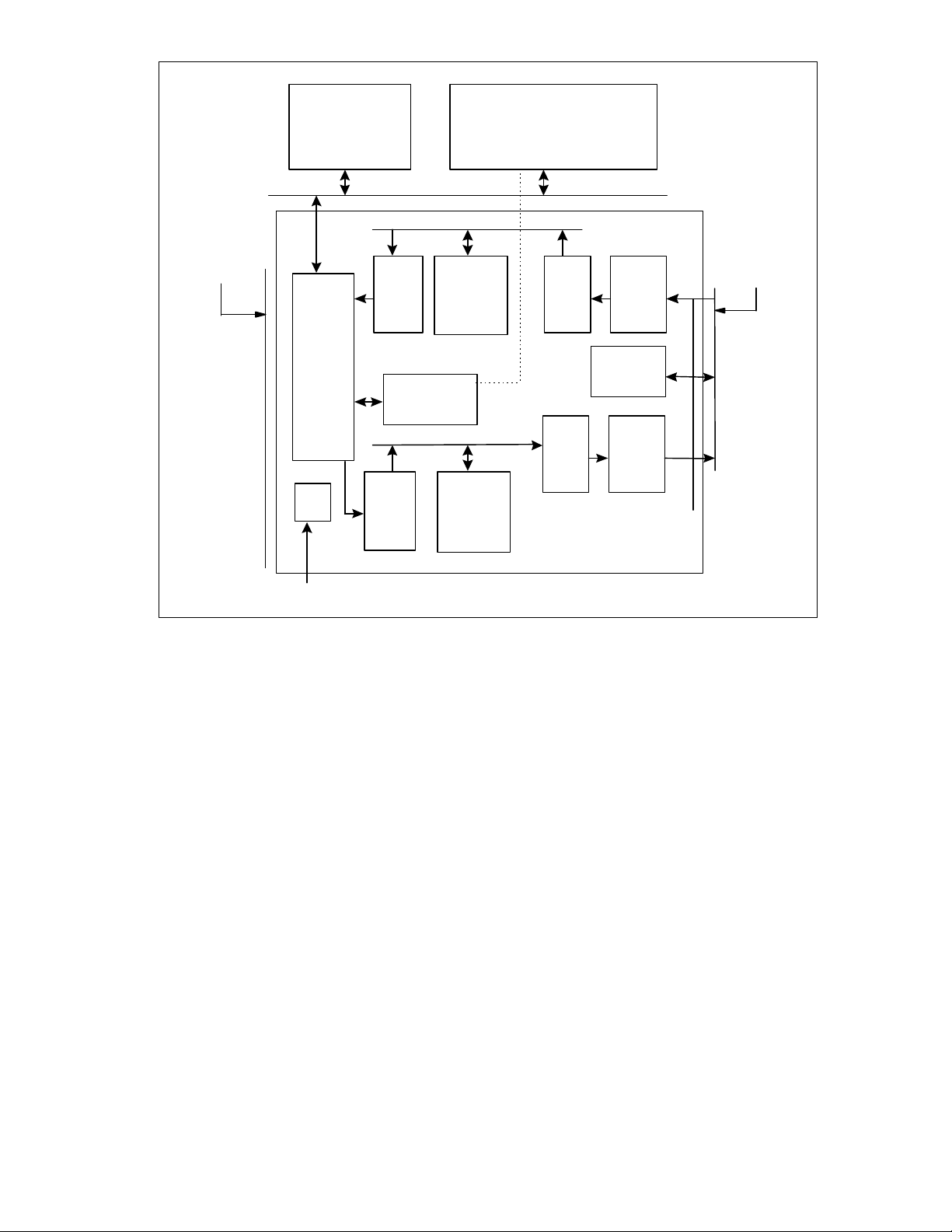
The LAN83C175 EPIC/C is a high-performance
Ethernet network controller designed to interface
directly to the CardBus Local Bus on one side
and to the 802.3 standard Media Independent
Interface (MII) on the other side. The network
interface can also be configured to
communicate directly with the LAN83C694
10BASE-T transceiver.
The LAN83C175 implements 802.3 Media
Access Control functions. It is capable of
running at Ethernet rates of both 100 Mbps and
10 Mbps. An MII compliant serial
management interface is provided to control
external media dependent transceivers. The
LAN83C175 is a two channel bus master (one
for transmit, one for receive) capable of
transferring data at the maximum CardBus
transfer rate of 132 Mbps. Buffer format in host
memory is controlled by an independent linked
list structure for each channel.
The LAN83C175's architecture is essentially
broken into two independent transmit and
receive processes which share CardBus bus
and network bandwidth. This architecture is
ideal for full-duplex networks where
transmission and reception of frames may occur
simultaneously. An internal arbiter controls
which process has access to the CardBus bus
at a given time (see section on "transmit/receive
arbitration for CardBus bus").
The transmit process consists of a DMA
controller, local transmit RAM, memory transfer
unit ("MTU") and CSMA/CD transmit state
machine. The transmit DMA copies packet data
from host memory into the local buffer. When
ready, the memory transfer unit feeds data from
the transmit buffer to the CSMA/CD state
machine, which is responsible for sending data
out on the network under the Ethernet protocol.
When transmission is complete, the transmit
DMA posts the transmit status into host
memory, interrupts the host (optionally) and
looks for the next transmit packet to be queued.
Like the transmit process, the receive process
consists of a DMA controller, local receive RAM,
memory transfer unit and CSMA/CD state
machine. Packets are received by the
CSMA/CD state machine and stored into local
memory by the receive MTU. The receive DMA
then copies the data from the local buffer into
host memory, posts the receive status and
interrupts the host. The LAN83C175 has several
features designed to minimize CPU utilization,
including the optional Receive Look-ahead
Buffering Mode, which eliminates the need to recopy the data from one host memory location to
another. Figure 2 on the following page shows
a block diagram of the LAN83C175.
10
SYS CLOCK
Flash EEPROM
for CIS and config.
Modem Chipset
Local Bus
32 bit Cardbus
BUS MASTER
SLAVE
PCI
INTERFACE
CLOCK
MULT.
PCI
RECEIVE
DMA
INTERNAL
RECEIVE
BUFFER
Receive
MTU
CSMA/CD
Management
Config and Status
REGISTERS
CSMA/CD
Transmit
PCI
TRANSMIT
DMA
Transmit
MTU
TRANSMIT
BUFFER
FIGURE 2 - EPIC/C BLOCK DIAGRAM
MII INTERFACE
Receive
MII

11
DMA OPERATION
NEXT DESCRIPTOR ADDRESS
The software driver controls the transmit and
receive DMA controllers through the I/O control
registers and through "buffer descriptors" in host
memory. There is an independent chain (linked
list) of descriptors for each DMA. Each
descriptor may point to a single data buffer
(which can hold a whole frame or part of a
frame) or to a fragment list, which in turn
contains a list of buffers for an entire frame.
Each descriptor also contains control and status
information and a pointer to the next descriptor.
TRANSMIT DMA
The following diagram shows the format of the
transmit descriptor table:
DWORD 0 - Status
31 0
TX LENGTH TX STATUS
7 - DEFERRING: This bit is set when the interframe gap state machine is deferring. If the
PHY has asserted the collision line as a result
of jabber, this bit will stay set indicating the
jabber condition. Always returns 0.
6 - OUT OF WINDOW COLLISION: This bit is
set if a collision is detected more than one slot
time after the start of transmission.
Transmission is aborted under these conditions.
5 - COLLISION DETECT HEARTBEAT: This bit
is set to a '1' during transmission of each
packet. It is set to '0' if a collision is detected
within 36 bit times of the end of each packet
transmission. If no collision is detected within
this window, it remains '1'. This bit always
returns zero in full duplex mode.
4 - UNDERRUN: This bit is set when the
transmit DMA is unable to supply the transmitter
enough data to maintain frame transmission.
Always returns 0.
BUFFER ADDRESS
CONTROL BUF LENGTH
Bit Number and Description
31 through 16: Transmit Length
15 - OWNER: Descriptor ownership bit - set to
0 when the host owns the descriptor, 1 when
the NIC owns the descriptor.
14 and 13 - Reserved.
12 through 8 - COLLISION COUNT: These bits
contain the number of collisions detected while
attempting to transmit the current packet. Bit 12
also indicates transmit abort for excessive
collisions.
3 - CARRIER SENSE LOST: This bit is set if the
carrier is lost during packet transmission.
Carrier sense is monitored from its rising edge
at the start of the outgoing frame's echo.
Transmission is not aborted upon loss of carrier.
This bit will always return zero in full duplex
mode.
2 - TRANSMITTED WITH COLLISIONS: When
set, this bit indicates the frame collided at least
once with another frame on the network. It is not
set for either out-of-window collisions or
excessive collision aborts.
1 - NON-DEFERRED TRANSMISSION: This bit
is set if the frame is transmitted successfully
without deferring. A deferred transmission can
only occur the first time an attempt is made to
send a packet. Collisions are not deferred
transmissions.
0 - PACKET TRANSMITTED: This bit is set to
indicate transmission of a packet without
excessive collisions or abort.

12
DWORD 1 - Data Buffer/Start of Fraglist Pointer
Bit Number and Description
31 through 0: Starting address of data buffer or
fragment list in host memory space. Fragment
list must be DWORD aligned. Data buffer may
be aligned on any byte.
early transmit threshold register (if early
transmit will be used), inter-packet gap program
register, interrupt mask register and general
control register. The software must also
program the CardBus Transmit Current
Descriptor Address Register (PTCDAR) with the
address in host memory where the first transmit
descriptor will be located.
DWORD 2 - Control/Data Length
Bit Number and Description
31 through 21 Reserved: Must always be set to
0.
20 - LASTDESCR: Indicates that this is the last
descriptor for the current transmit frame (Not
used when FRAGLIST = 1).
19 - NOCRC: Disable automatic CRC
generation for this packet when set.
18 - IAF: When set, interrupt after this frame is
transmitted.
17 - LFFORM: Fragment list format - A "1"
indicates that the data length field comes before
the pointer in the fragment list. "0" indicates
that the pointer comes before the data length.
16 - FRAGLIST: Indicates that this descriptor
points to a fragment list.
15 through 0 - Length of data buffer (Not used
when FRAGLIST = 1).
DWORD 3 - Next Descriptor Pointer
Bit Number and Description
31 through 2 - Starting address of next
descriptor in host memory space. Descriptors
must be DWORD aligned.
1 - 0: Unused.
The software driver initializes the transmit
process by writing the transmit control register,
To begin packet transmissions, the software
driver programs the transmit descriptor chain
with the appropriate number of entries and then
sets the TXQUEUED bit in the COMMAND
register.
Descriptor entries describe the location of
transmit data in host memory. Data for a single
transmit frame may not always be in a
contiguous block in host memory. Therefore,
the LAN83C175 allows the software to specify
multiple data buffers for each frame. Each
frame may be queued in one of two ways, both
of which may be used in the same descriptor
chain:
1) Direct Queuing Method (descriptors point
directly to the transmit data buffers):
One or more descriptors may be used to point
to a single frame. All descriptors must have the
FRAGLIST control bit set to 0. The first
descriptor must contain the transmit length for
the frame. The last descriptor for the frame
must have the LASTDESCR bit set to 1 and
contain the desired values for the TXIAF and
NOCRC control bits. When the TXQUEUED bit
is set, the transmit DMA will read the from the
location in host memory pointed to by its
Current Descriptor Address register. If the
ownership bit in the descriptor is equal to 1 then
the LAN83C175 will accept the descriptor and
update its Current Descriptor Address register
with the value in the Next Descriptor Address
field. Otherwise the TXQUEUED bit will be
cleared (and the transmit queue empty (TQE)
interrupt set) and the Current Descriptor
Address register will not be changed. The
Transmit Length field in the first descriptor will

13
always contain the number of bytes to be
transmitted on the network, and not necessarily
the number of bytes in the transmit buffers. The
transmit DMA will begin copying data from the
location in host memory specified by the Buffer
Address field in the first descriptor. It will
compare the transmit byte count to the Data
Length field, and copy the lesser number of
bytes into the local transmit RAM. If early
transmit is enabled, the LAN83C175 will
automatically initiate transmission on the
network when the number of bytes specified in
the Early Transmit Threshold register have been
loaded into the transmit buffer.
If the transmit byte count is less than the Data
Length field, or the LASTDESCR bit is set, then
the frame copy is complete after the buffer has
been read. The LAN83C175 will initiate
transmission on the network if it has not already
done so.
If the Data Length field is less than the transmit
byte count and the LASTDESCR bit is not set,
then the LAN83C175 will attempt to read
another descriptor. The transmit DMA will
proceed as before, however this time it will not
read the Transmit Length field, but instead use
the remaining number of bytes in its transmit
byte counter (original byte count minus bytes
already copied). This process will continue until
a descriptor is read with the LASTDESCR bit set
or the transmit byte count reaches zero. If
LASTDESCR is set and the total number of
bytes copied do not add up to the transmit byte
count, then the transmit MTU will pad the frame
with random data after copying all of the valid
data out of the transmit RAM. The CSMA/CD
state machine will not append the automatically
generated CRC to the frame if NOCRC is set in
the last descriptor for the frame.
After the LAN83C175 has initiated the first
transmission, it will check to see if there are any
more frames in the transmit queue. If the
software does not have another frame ready for
transmission, then the ownership bit in the next
descriptor must be 0. If the ownership bit is 0,
then the LAN83C175 will clear TXQUEUED and
set the transmit queue empty interrupt. If the
ownership bit is 1, then the LAN83C175 will
begin copying the next frame into the local
transmit RAM. The DMA will continue copying
transmit buffers until the frame has been
completely loaded into the transmit RAM or the
first transmission has completed. If the copy
completes while the first transmission is still in
progress, then the LAN83C175 will stop and
wait. When the transmission is finished, the
LAN83C175 will post the status into the first
descriptor for that frame and immediately
initiate the second transmission. If the
transmission completes before the copy is done,
the LAN83C175 will pause after the current
transmit buffer has been copied and post the
status from the first frame. If the early transmit
threshold has already been exceeded then the
second transmission will be initiated
immediately. The transmit DMA will then
continue by reading the next descriptor for the
copy in progress.
When the transmit status is posted, the
ownership bit will be written as 0 to indicate that
the host now owns that descriptor again. The
Transmit Length field will not be overwritten. If
TXIAF is true in the last descriptor for the frame,
then the transmit complete (TXC) interrupt will
be set. When there are no frames left in the
queue and the last transmission has completed
on the network, the transmit DMA will set the
transmit chain complete (TCC) interrupt and
return to its idle state.
2) Fragment List Method (descriptor points
to a fragment list)
This method of queuing a transmit frame is
much like the first method, except that each
frame is always specified by one descriptor
which points to a list of buffers (fragment list)
instead of the buffers themselves. The
FRAGLIST bit in the descriptor must be set to 1
and the LFFORM bit must properly indicate the
format of the fragment list. The first entry in the
fragment list tells how many data buffers

14
(fragments) are listed. Up to 63 fragments are
allowed. The remaining entries specify the
starting address and length of each buffer.
As in the direct queuing method, the transmit
DMA will copy fragments one at a time into the
local buffer until Transmit Length bytes have
been copied or all of the fragments have been
read. If early transmit is enabled, transmission
will be initiated when enough bytes have been
copied to meet the early transmit threshold.
Otherwise transmission will be initiated when
the entire copy is complete.
When more than one frame is queued, the
transmit DMA will begin copying a second frame
while the first is transmitting. It will continue
copying fragments until the entire frame is
loaded or the first transmission has completed.
If the copy completes while the first
transmission is still in progress, then the
LAN83C175 will stop and wait. When the
transmission is finished, the LAN83C175 will
post the status into the first descriptor and
immediately initiate the second transmission. If
the transmission completes before the copy is
done, the LAN83C175 will pause between
fragments to post the status and then resume
the copy. If the early transmit threshold has
already been exceeded then the second
transmission will be initiated immediately.
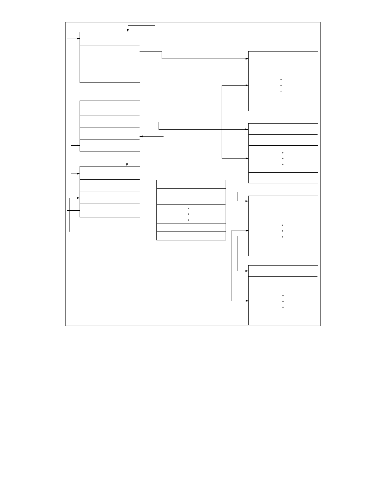
Figure 3 on the following page shows a drawing
of the Transmit Buffer Structure.
15
TX LENGTH/STATUS
BUFFER ADDRESS
CONTROL/BUF LENGTH
NEXT DESCR. ADDRESS
TX LENGTH/STATUS
BUFFER ADDRESS
CONTROL/BUF LENGTH
NEXT DESCR. ADDRESS
TX LENGTH/STATUS
FRAME 1 STATUS
FRAME DATA
FRAME 1
FRAME DATA
LAST DESCR - 1
FRAME 2 STATUS
BUFFER ADDRESS
CONTROL/BUF LENGTH
NEXT DESCR. ADDRESS
FRAGLIST - 1
NUMBER FRAGS
PTR1(FRAG LENGTH)
FRAG LENGTH(PTR1)
PTRn(FRAG LENGTHn)
FRAG LENGTHn(PTRn)
FRAME 2
FIGURE 3 - TRANSMIT BUFFER STRUCTURE
FRAME DATA
FRAME DATA

16
The software may add transmit frames to the
queue at any time. If the transmit process is
already running (TXQUEUED may still be set),
then all of the descriptor and fragment list
fields for the new frame must be valid
BEFORE the ownership bit in the first
descriptor is set. After the descriptors are
written, the TXQUEUED bit should be set.
TXQUEUED can be written regardless of
completion status and will ensure that the
latest frame is transmitted. If the LAN83C175
reaches the end of the transmit queue before
the new frame has been added, a transmit
chain complete interrupt is generated for the
old portion of the queue and another transmit
chain complete interrupt will be generated
when the added portion completes.
Interrupting Transmit Chain
The host may interrupt the transmit chain
before all frames have been transmitted by
setting the STOP_TDMA bit in the command
register. Setting this bit forces TXQUEUED to
0. The transmit DMA will finish copying any
frame that it has already begun, and transmit
all frames that have been loaded into the
transmit ram. After the transmit DMA has
posted the status for the last frame, it will set
the transmit chain complete interrupt and
return to its idle state (exactly as if the next
frame in the queue was owned by the host). If
the DMA reads a descriptor owned by the host
while a copy is still in progress, it will set the
transmit queued empty interrupt and wait for
the descriptor to be re-queued. It will not
return to the idle state until the copy is
completed.
Transmit Buffer Full
Whenever the local transmit RAM becomes
full, the transmit DMA will wait until more
space is available before loading any more
data. Space is freed up as the transmit MTU
reads data from the local RAM and updates its
pointers. In some cases, the transmit MTU will
leave its pointers at the beginning of a frame until
it knows that the transmission will not have to be
retried. Automatic retries can occur due to
collisions or early transmit underruns.
Transmit Underrun
A transmit underrun occurs in early transmit mode
when the transmit DMA can not keep up with
transmission on the network. Data must be read
from the local RAM before it is available. Usually,
when an underrun occurs, the transmit MTU will
generate a transmit underrun (TXU) interrupt and
update its transmit status register. The transmit
DMA will continue to operate as though nothing
has happened. The software driver will be
allowed to read the transmit status value from
TXSTAT and set the "transmit underrun go"
(TXUGO) bit to tell the MTU to retry the frame.
The MTU will re-transmit the entire frame out of
the local transmit ram. When transmission has
completed successfully, the DMA will post the
transmit status for the retry to the descriptor for
that frame. Operation will continue as it normally
would for a non-underrun situation.
The only exception to this behavior is when the
transmit MTU can not automatically retry an
underrun frame. This happens when the frame
size is larger than the transmit RAM (1.5 Kbytes)
and the transmit DMA has overwritten the
beginning of the frame before the underrun
occurs. If such an event occurs, the transmit
DMA will abort the copy and reset its pointers to
the first descriptor for that frame. The DMA will
clear the TXQUEUED bit and return to its idle
state. Transmit queue empty and transmit chain
complete interrupts will be generated along with
the transmit underrun interrupt. The software
driver must set TXUGO to reset the transmit MTU
and then set TXQUEUED if it wants to retry the
frame. The frame will be re-copied from scratch
out of host memory when TXQUEUED is set.

17
Maximum Transmit Size and Burst Rate
Data Buffer Pointer
The transmit DMA supports frame sizes up to
64 Kbytes. The maximum size for a single
data buffer (fragment) is also 64 Kbytes. The
transmit DMA will run at the maximum
CardBus data rate of 132 MBytes/s when the
target memory system supports zero wait
state reads. The transmit DMA will burst as
many words as it can before having to
relinquish the CardBus bus. It is capable of
bursting data continuously with no wait states
(even when a transmission is active on the
network) until the transmit RAM becomes full.
The transmit DMA, however, will most likely
lose possession of the CardBus bus several
times before it can fill the entire 1.5 Kbyte
transmit buffer.
Bit Number and Description
31 Through 4 - Unused
5 through 0 - Number of fragments in this
fragment list (1-63). (Note: programming 0
into this field results in 64 fragments).
31 through 0 - Starting address of data buffer in
host memory space. Data buffer may be aligned
on any byte.
31 through 16 - Unused
15 through 0 - Length of data buffer.
RECEIVE DMA
The diagram below shows the format of the
receive descriptor table:
31 0
RX LENGTH RX STATUS
BUFFER ADDRESS
CONTROL
NEXT DESCRIPTOR ADDRESS
BUF LENGTH

18
DWORD 0 - Status
Bit Number and Description
31 through 16 - RECEIVE FRAME LENGTH:
Number of bytes in the received frame.
2 - CRC ERROR: This bit is set when a frame's
computed CRC does not match the CRC
appended to the frame. If the frame is a runt, this
bit will be clear. In MII mode, this bit will also be
set if receive error was asserted on the MII
interface during reception of the frame.
15 - OWNER: Descriptor ownership bit - set to
“0” when the host owns the descriptor, set to
“1” when the NIC owns the descriptor.
14 - HEADER COPIED: Set when the receive
status is posted after a header copy.
13 - FRAGMENT LIST ERROR: Set when all
buffers in the fragment list have been filled
before the entire receive frame is copied.
12 - NETWORK STATUS VALID: Set when
bits 6 - 0 contain the status from the current
frame and bits 31-16 contain the frame length.
In the case of a header copy or fragment list
error, the receive status from the current
frame may or may not be posted. In all other
cases this bit will be set.
11 through 7 - Reserved
6 - RECEIVER DISABLED: This bit is set
when the receiver is in monitor mode. Always
returns 0.
5 - BROADCAST ADDRESS RECOGNIZED:
This bit is set when a broadcast address has
been recognized.
4 - MULTICAST ADDRESS RECOGNIZED:
This bit is set when a multicast address which
passes the hash filter has been recognized.
1 - FRAME ALIGNMENT ERROR: This bit is set
if a CRC error has occurred and the frame is not
byte aligned.
0 - PACKET RECEIVED INTACT: This bit is set
when a packet is received into the buffer space
without error.
DWORD 1 - Data Buffer/Start of Fraglist
Pointer
Bit Number and Description
31 through 0 - Starting address of data buffer or
fragment list in host memory space. Fragment
list must be DWORD aligned. Data buffer may
be aligned on any byte.
DWORD 2 - Control/Data Length (or Frame
Offset)
Bit Number and Description
31 through 19 - Reserved: Must always be set to
0.
18 - HEADER: Indicates that this descriptor is for
a header copy.
17 - LFFORM: Fragment list format - a 1 indicates
that the data length field comes before the
pointer in the fragment list. A 0 indicates that the
pointer comes before the data length.
3 - MISSED PACKET: This bit is set when a
packet with a recognized address and without
errors (or with masked errors) is not buffered
because the device is in monitor mode. This
bit is also set when the packet overflows the
receive buffer space and cannot be received.
Always returns 0.
16 - FRAGLIST: Indicates that this descriptor
points to a fragment list.
15 through 0 - Length of data buffer (when
FRAGLIST = 0) or Offset into frame where copy
begins (when FRAGLIST = 1).

19
DWORD 3 - Next Descriptor Pointer
Bit Number and Description
31 through 2 - Starting address of next
descriptor in host memory space. Descriptors
must be DWORD aligned.
1 - 0: Unused.
The software driver initializes the receive
process by writing the receive control register,
interrupt mask register and general control
register. The software must also program the
CardBus Receive Current Descriptor Address
Register (PRCDAR) with the address in host
memory where the first receive descriptor will
be located.
To allow packet receptions, the software driver
programs the receive descriptor chain and
then sets the RXQUEUED and START_RX
bits in the COMMAND register. Setting
START_RX brings the CSMA/CD receiver
online. The receive DMA is enabled by setting
RXQUEUED. The software driver should set
RXQUEUED before or simultaneous to
bringing the receiver online so that the
receiver does not overflow the local buffer
while waiting for a descriptor to be queued.
The first descriptor must be valid before the
RXQUEUED bit is set. The first descriptor will
be read as soon as it is queued, even if no
receptions have occurred on the network.
The receive lookahead method offers
maximum performance in most cases.
Free Buffer Pool Method
In this mode the software driver pre-allocates
a pool of free buffers for frames received by
the LAN83C175. The ONECOPY bit in the
general control register must be set so that
the each frame may be copied into the buffer
pool without host intervention. The descriptors
for the free buffer pool may point directly to
the buffers, or point to a fragment list which in
turn specifies the buffers.
When the RXQUEUED bit is set, the receive DMA
will attempt to read the first descriptor from the
address pointed to by its Current Descriptor
Address register. If the ownership bit is 0, the
RXQUEUED bit will be cleared (and the receive
queue empty (RQE) interrupt set) and the Current
Descriptor Address register will not be changed.
If the ownership bit is equal to 1, the LAN83C175
will accept the descriptor and update its Current
Descriptor Address register with the value in the
Next Descriptor Address field. The LAN83C175
will save the descriptor information until a frame
is received. If the fraglist control bit is also 1, then
the receive DMA will read and save the address
pointer and data length for the first buffer in the
fragment list. The offset field in the descriptor
(see buffer length field) should be set to zero,
otherwise the copy will not begin at the start of the
frame. The fragment list format for the receive
DMA is identical to the format for the transmit
DMA.
As soon as a frame is received, the LAN83C175
will begin copying it from the local receive buffer
into the allocated buffer in host memory. If early
receive is enabled, the LAN83C175 can begin the
copy while reception is still in progress. The
receive DMA always monitors the local buffer
contents so that a receive underflow can never
occur. As soon as the receive DMA has copied
the number of bytes in the CardBus Receive Copy
Threshold register, it will set the receive copy
threshold (RCT) interrupt. When the receive DMA
has copied the entire packet from the local RAM
into host memory, it will post the receive status
into the first descriptor for the frame and set the
receive copy complete (RCC) interrupt. The DMA
will read the next descriptor and, if owned by the
NIC, check to see if there are any more frames to
copy out of the local RAM. If the receive DMA fills
the first host buffer before the entire frame has
been copied, it will read the next descriptor or
fragment list entry to find more buffer space. This
process will continue until the entire frame has

20
been copied. If the DMA reads a descriptor
with the ownership bit set to 0, it will clear the
RXQUEUED bit (and set the receive queue
empty interrupt) and wait for a new descriptor
to be queued. In fragment list mode, the
receive DMA always expects the fragment list
to contain enough buffer space for the entire
frame.
If all the buffers in the fragment list are filled
before the copy is finished, then the DMA will
abort the copy and set the fragment list error
bit in the PRSTAT register. The DMA receive
status will be posted to the descriptor for that
frame and the RXQUEUED bit will be cleared.
If early receive is enabled, the network portion
of the receive status may not yet be valid, as
indicated by the RSV bit posted in the status.
The software driver may poll the RSV bit in the
interrupt status register, and when it returns a
1 read the receive status from PRSTAT. The
software may attempt to re-copy the frame by
setting the RXQUEUED bit again, or may
discard the frame by setting the NEXTFRAME
bit before or simultaneous to setting
RXQUEUED. If RXQUEUED is set after or
along with NEXTFRAME, the DMA will begin
to copy the next frame (if any) in the receive
buffer.
bit may be set at any time, even if the receive
DMA is still active.
Receive Lookahead Method
When this buffering method is used, the
LAN83C175 first copies only the header of a
frame into host memory, and then waits for a
queue from the software driver before copying the
rest of the frame. The software usually specifies
the final destination of the frame data with a
fragment list. The advantage to this buffering
method is that the LAN83C175 may copy frame
data to its final destination instead of a temporary
buffer space, so the software driver is not
required to re-copy the data from one host
memory location to another.
In receive lookahead mode, frames are usually
copied into the host memory one at a time, and a
handshake is performed between the software
driver and the LAN83C175 during each frame.
The handshake is performed using the
RXQUEUED and NEXTFRAME bits in the
COMMAND register, and the receive copy
complete (RCC) and header copy complete (HCC)
interrupts. The control bits in the receive
descriptors are also used to direct the receive
DMA.
Note: The DMA rounds the number of bytes
copied up to the nearest dword.
If the receive buffer does not start on a dword
boundary, then the number of bytes in the
receive buffer may be slightly less (up to 3
bytes) than the receive copy threshold when
the interrupt is generated.
Adding Receive Buffers to the Pool
The software driver adds buffers to the pool by
writing the appropriate descriptors and setting
their ownership bit to 1. If the receive DMA
has stopped (RXQUEUED is cleared), then the
software must set the RXQUEUED bit to
queue the new descriptors. The RXQUEUED
The software driver begins by setting up a buffer
for the header of the first frame and setting
RXQUEUED. The HEADER control bit in the
descriptor should be set and the FRAGLIST bit
should be cleared. The buffer address pointer
and length are specified directly in the descriptor.
When a frame is received, the receive DMA
begins copying the beginning of the frame into
the header buffer until the buffer is full, or until the
entire frame has been copied. The copy may
begin before the entire frame has been received if
early receive is enabled. When the header copy
is complete, the receive DMA status will then be
posted to the descriptor for the header buffer, and
the header copy complete interrupt will be set. If
reception from the network has completed, then
the network portion of the posted status will be

21
valid, and the RSV bit will be set to 1. In early
receive mode, the receive DMA status may be
posted before the network status for the frame
is available, in which case the RSV bit in the
descriptor will be set to 0. If the entire frame
fits into the header buffer, then the network
receive status will always be posted with the
frame. After a header copy, the receive DMA
always clears the RXQUEUED bit (also setting
the receive queue empty interrupt, which may
be masked) and waits in the idle state for the
software driver to queue a fragment list for the
rest of the frame.
After examining the header data, the software
driver may discard the frame or have it copied
into host memory as many times as it would
like. The software requests copies of the frame
by programming descriptors (and fragments
lists) and setting RXQUEUED without setting
NEXTFRAME. The frame is copied exactly as
it would be in the free buffer pool mode, with
the exception that the offset field is used with
fragment list copies. The software may not
need all of the bytes at the beginning of the
frame to be copied, so it may specify an offset
into the frame where the copy should begin.
The offset field shares a location in the
descriptor with the buffer length field because
the buffer length is not specified in a descriptor
for a fragment list. The receive DMA copies
the frame into host memory beginning from
the byte number specified in the offset. If the
offset field is not zero, then the copy will not
begin until the entire frame has been received
from the network, even if early receive is
enabled. This is so that the receive DMA does
not copy invalid data if the offset is greater
that the number of bytes that have been
received so far. Usually, the entire frame will
have been received before the fragment list is
available.
When the copy is finished, the receive status
is posted and the receive copy complete
interrupt is set. The receive DMA will then
read the next descriptor, and if the ownership
bit is set it will immediately begin to copy the
same frame into host memory again. If the
descriptor is owned by the host, then
RXQUEUED will be cleared (and receive queue
empty interrupt set) and the receive DMA will wait
in the idle state for another command. If the
software driver wants another copy of the frame, it
may queue another descriptor and set
RXQUEUED without setting NEXTFRAME. This
procedure will be repeated until the software
chooses to go on to the next frame.
The software driver discards a frame by setting
NEXTFRAME before or simultaneous to setting
RXQUEUED. If RXQUEUED is set after or along
with NEXTFRAME, the receive DMA will begin to
copy the next frame (if any) in the receive buffer.
The next descriptor queued should contain a
header buffer for the next frame.
Occasionally, the software driver may want to
discard a frame immediately after reading its
header, but still read the receive status for that
frame. If the valid network status is not posted in
the descriptor, then the software driver may read
it from the PRSTAT register. The driver must
first set NEXTFRAME and RXQUEUED to
discard the frame, as described above. However,
the next descriptor in the receive descriptor list
must have the ownership bit cleared (host still
owns descriptor). This allows the LAN83C175 to
update the PRSTAT register without starting to
copy the following frame. The software driver
must poll the RQE (receive queue empty) interrupt
to determine when the status is available. When
the RQE interrupt is set, the driver may read the
receive status from the PRSTAT register. The
receive status valid bit in the interrupt status
register will not indicate when the receive status
is available.
When the software driver only wants one more
copy of the current frame, it does not have to wait
for the copy to complete before setting
NEXTFRAME. The software may set
NEXTFRAME immediately after setting
RXQUEUED (on the following I/O write) and begin

22
to queue the header descriptor for the next
frame. After the header descriptor is queued,
the software may set RXQUEUED again to
guarantee that the header descriptor is
recognized. When the DMA is finished
copying the first frame, it will immediately read
the next descriptor and may begin copying the
next header without waiting for the software to
respond to an interrupt.
Note: Software must never set NEXTFRAME
more than once per frame. NEXTFRAME
may only be set when the copy is in
progress or has already been completed.
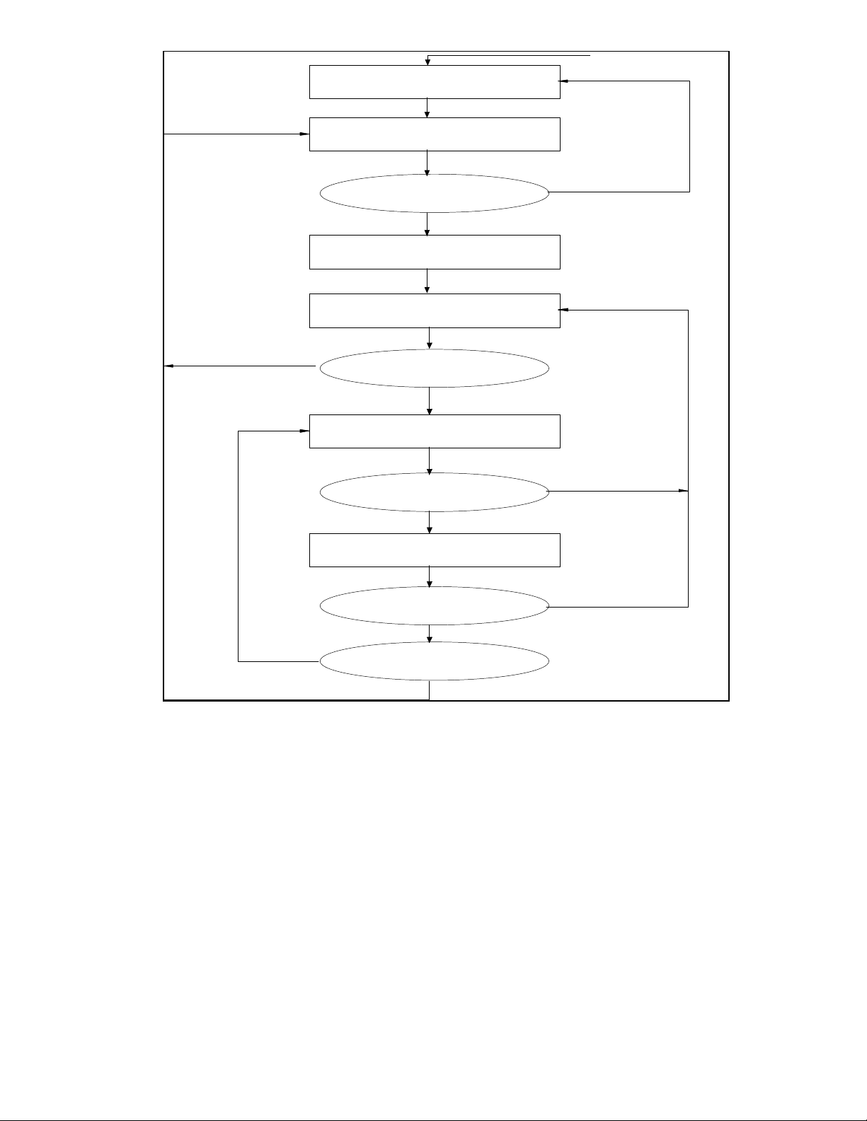
Figure 4 shows an example of the Receive Buffer
Structure, and Figure 4 shows a flow diagram for
the Receive Buffering Method.
23
WAIT
READ DESCRIPTOR
RESET
RXQUEUED SET
HEADER BIT SET
GO TO NEXT
FRAME
TRUE
OWNER
NIC
COPY HEADER
POST STATUS
WAIT
NEXTFRAME
READ DESCRIPTOR
OWNER
NIC
COPY FRAME
POST STATUS
RDMA STOPPED
(RXQUEUED=0)
HOST/CLEAR RXQUEUED
DONE/CLEAR RXQUEUED SET HCC
RXQUEUED SET
FALSE
(HEADER BIT CLEARED)
HOST/CLEAR RXQUEUED
DONE/SET RCC
YES
NO
FALSE
NEXTFRAME
TRUE
FIGURE 4 - RECEIVE LOCKAHEAD BUFFERING FLOW

24
Stopping the Receive DMA
Maximum Receive Size and Burst Rate:
The receive DMA may be halted by setting the
STOP_RDMA bit in the command register.
Setting this bit forces RXQUEUED to 0. The
CSMA/CD receiver should also be taken off-line
to prevent it from continuing to buffer receive
frames. The receive DMA will attempt to
complete any copy in progress. When finished,
it will return to its idle state. When the
CSMA/CD receiver is off-line and has also
returned to its idle state, the RXIDLE bit in the
interrupt status register will become true (1). If
the DMA reads a descriptor owned by the host
before it completes its current copy, it will set
the receive queued empty interrupt and return to
the idle state. The DMA will continue the copy
when more buffers are queued. The software
driver can tell if a copy is still in progress or
if there are any more frames in the local receive
RAM by reading the RCIP and RBE bits in the
interrupt status register.
The STOP_RDMA bit can be set when the
receive DMA has read and saved the
information in a descriptor, but there are no
frames in the local receive RAM. In this case,
the receive DMA will reset its current descriptor
pointer back to that descriptor and return to the
idle state. When the RXQUEUED bit is set
again, the DMA will be re-read the descriptor.
The receive DMA supports frame sizes up to 64
Kbytes. The maximum size for a single data
buffer (fragment) is also 64 Kbytes. The receive
DMA will run at the maximum CardBus data
rate of 132 Mbps when the target memory
system supports zero wait state writes. DMA
bursts at this rate will run for a limited number
of dwords. The length of each burst is
dependent on the FIFO threshold level and
access to the local receive RAM. The receive
DMA loads data into the receive burst FIFO at a
maximum rate of 100 Mbps (when reception is
not in progress) or 83 Mbps (when reception is
in progress). The receive DMA will
automatically initiate a burst on the CardBus
bus whenever the FIFO reaches programmed
threshold level. The receive DMA will continue
to load data into the FIFO while it is being
emptied onto the CardBus bus. The burst will
continue until the FIFO is empty or the receive
DMA loses control of the CardBus bus (to the
internal transmit DMA or to another CardBus
master). Another burst will begin when the
FIFO again reaches the threshold level, or when
the last of the data for the current copy has been
loaded into the FIFO. The CardBus bus will be
requested immediately if the receive DMA loses
possession of the bus while the FIFO is above
the threshold level.
THR_SEL
[1]
THR_SEL
[0]
THRESHOLD
LEVEL
0 0 1/4 Full (32
Bytes)
0 1 1/2 Full (64
Bytes)
1 0 3/4 Full (96
Bytes)
1 1 Full (128 Bytes)

25
A lower threshold allows the LAN83C175 to
begin moving data on the CardBus bus sooner,
while a higher threshold may allow longer
bursts. A higher threshold level will not result in
parity generation and error detection. This block
is also responsible for responding to all slave
operations according to CardBus bus protocol
(including address recognition and parity
generation and error detection).
TRANSMIT/RECEIVE ARBITRATION FOR
CardBus BUS
Another major function of the CardBus Bus
Master/Slave Interface block is to arbitrate
between the transmit and receive DMA
controllers for access to the CardBus bus. Two
programmable priority select bits determine the
relative priority of each DMA controller. When
RXPRI is set, the receive DMA process may
preempt the transmit DMA process (when the
CardBus Latency Timer expires). The receive
DMA takes control of the CardBus bus if a
transmit fragment copy is suspended by a
target disconnect before the Latency Timer
expires. When RXPRI is cleared, the receive
process has to wait until the transmit DMA is
finished before it has access to the CardBus
bus. When TXPRI is set, the transmit DMA
process may preempt the receive DMA process
(when the CardBus Latency Timer expires). The
transmit DMA also takes control of the CardBus
bus if a receive fragment copy is suspended
by a target disconnect before the Latency
Timer expires. When TXPRI is cleared, the
transmit process has to wait until the receive
DMA is finished before it has access to the
CardBus bus. When both bits are set, either
process may preempt the other. When neither
bit is set, no preemptions occur. (Note:
Preemption does not occur when either process
has only one dword left to transfer).
SYSTEM ERRORS
There are four types of CardBus bus errors that
are considered fatal by the LAN83C175. They
are Master Abort, Target Abort, Address Parity
Error and Data Parity Error (see interrupt status
register for details). If any of these errors
occurs, the LAN83C175 will set the appropriate
interrupt and immediately discontinue all DMA
activity. The receiver will automatically be taken
off-line and any transmissions in progress will
be completed without a valid CRC appended (in
case transmit data was corrupted). Normal
operation may only be resumed by resetting the
LAN83C175 with the soft reset bit. The
software driver should make sure the transmitter
and receiver have returned to their idle states
(by polling the TXIDLE and RXIDLE bits in the
interrupt status register) before resetting the
device.
BIG/LITTLE ENDIAN SUPPORT
In order to run in Big Endian machines, the
LAN83C175 can be programmed to swap bytes
on the data bus in certain circumstances. In
Macintosh Power PC computers the bridge
between the Big Endian processor data bus and
the Little Endian CardBus bus swaps the order
of the bytes on the data bus (during data phase
only - addresses are never modified). This
means that byte size quantities transferred over
the data bus will always end up in the correct
location for their given address, but when 32 bit
(dword) quantities are transferred they will end
up with their bytes reversed.
When programmed into Big Endian mode,
the LAN83C175 will automatically swap the data
bytes internally when reading or writing
descriptor tables or fragment lists. This allows
the software driver to treat the descriptor and
fragment list entries as 32 bit quantities and not
worry about byte ordering.

26
In order to comply with the CardBus
specification, the LAN83C175 will not swap the
data bytes on reads or writes to the
configuration or control register space. The
software driver will be responsible for correctly
interpreting the bytes when performing 32 bit
register read or writes on a Big Endian
machine.
When reading or writing Ethernet packet data,
the LAN83C175 will not perform any byte
swapping internally because the data on the
CardBus bus will already be in the correct order.
27
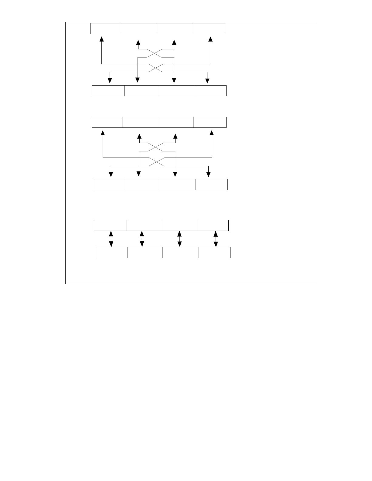
3 2 1 0
31
0
Byte Transfer
Little Endian (PCI) Bus
PCI Bridge Action
0 1 2 3
7 0 7 0 7 0 7 0
Control Register dword transfer:
3 2 1 0
0 1 2 3
7
Descriptor/Fragment list dword transfer:
31 0
0 15 8 23 16 31 24
3 2
0 1 2 3
1 0
Big Endian (PowerPC) Bus
Byte Transfer
Little Endian (PCI) Bus
PCI Bridge Action
Big Endian (PowerPC) Bus
Byte Transfer
Little Endian (PCI) Bus
PCI Bridge Action plus
internal SMC91C120 swap
Big Endian (PowerPC) Bus
5
FIGURE 5 - LITTLE ENDIAN/BIG ENDIAN BYTE TRANSFER
The number in the box refers to the address of
the byte. The numbers above and below the
boxes refer to the bit number (the bit
ordering increases from LSB to MSB for both
formats, although some other documents
choose to label them differently).

MAC Operation
The LAN83C175 is compliant with the 802.3
standard CSMA/CD protocol for 10 or 100
Mbps Ethernet networks.
MAC Receiver
The LAN83C175 CSMA/CD receiver is capable
of operating with network data rates of 10 and
100 Mbps. It supports current implementations
of 10 Mbps physical layer devices, and the
802.3u Media Independent Interface for 10 and
100 Mbps.
Basic Function
The receiver processes serial or nibble wide
data streams at data rates of 10 Mbps or 100
Mbps. The receiver detects start of frame,
provides destination address recognition and
filtering, transfers recognized frames to
memory, and provides error detection and
reporting.
Interface to Physical Layers
The receiver interfaces to the physical layer in
serial or parallel mode. When in the serial
mode, data is transferred serially on the RXD[0]
pin synchronous to the falling edge of the
receive data clock (RX_CLK). RX_CLK is a 10
MHz clock signal recovered by the physical layer
device from the data stream. The CRS and
COL signals provide carrier sense and collision
detect respectively.
In parallel mode, the physical layer device
transfers data to the LAN83C175 four bits at a
time on the RXD[3-0] data bus. The data is
transferred synchronously to the falling edge of
RXC. The signal Receive Data Valid (RX_DV)
informs the MAC of the RXD bus status. The
physical layer can also notify the LAN83C175 of
invalid data on the medium with the Receive
Error signal (RX_ER). Selecting the receiver
interface mode is performed by programming
the MII Configuration register.
Packet Reception/Serial Mode
After detection of carrier, serial bits received on
RXD[0] are synchronized to the rising edge of
RX_CLK. Each bit is shifted through an 8-bit
shift register scanning for a Start of Frame
Delimiter (SFD) pattern of '10101011' received
from left to right. Following detection of SFD, all
bits are byte aligned in the serial to parallel shift
register. Bits are received from least significant
bit to most significant bit within the byte. Data
from the shift register is transferred to the
receive FIFO where it waits for the receive DMA
to transfer it into local memory. The receive
process continues while CRS or COL are active.
Parallel Mode
Packet reception begins with the first nibble after
detecting RX_DV active. Nibbles transferred on
RXD[3-0] are synchronized to the rising edge
of RX_CLK and shifted into a 2-nibble shift
register. RXD[0] is the least significant bit
(LSB). SFD is detected when the shift register
contains the value '10101011' from LSB to
MSB. The preamble and SFD pattern received
from the PHY device is required to be nibble
aligned. Bytes are aligned in the 2-nibble shift
register after detection of SFD. Each byte is
transferred to the receive FIFO. Packet
reception continues while RXDV is active and
ends with the nibble preceding the falling edge
of RX_DV. While RX_DV is de-asserted, the
value of RXD[3-0] has no effect on the MAC.
Error Detection
The receiver computes the CRC of incoming
frames for all data following the detection of
SFD in both parallel and serial mode until the
end of frame, including the CRC field.
28
 Loading...