

SMSC LAN83C171 Datasheet

LAN83C171
ADVANCE INFORMATION
LAN83C171 - EPIC/XF
ACPI/PC 97 Compliant Integrated PCI 10/100
Mbps Fast Ethernet Controller
FEATURES
• IEEE 802.3 Compatible 10/100 Mbps Fast
Ethernet Controller
• Fully Compliant Glueless PCI Version 2.1
Bus Interface
• Support Included for CardBus Status
Registers
• PCI Universal 3V/5V Output Drives
• Preemptive Interrupt Support for Efficient
Network Packet Processing
• High Performance Two Channel Bus Master
(132 Mbps)
• Scatter/Gather DMA Capability
• Programmable Burst Length Counter
• ACPI Compliant for
- PCI Bus Class Specification
- Network Device Class Specification
• PC 97 Compliant
• Wake-Up on Magic PacketTM Detection
and/or Network Link-Down Occurrence
• Special Low Power State Mode For
Scanning Magic PacketsTM Upon PCI Bus
Power Loss
• Supports Chaining of Transmit Packets
• Optional Early Transmit and Early Receive
• Optional Receive Lookahead Buffering
Mode
• Automatic Rejection of Runt Packets
• Automatic Retransmission of Collision
Frames from Internal Buffer
• Automatic Padding of Short Frames
• 4.5 Kbyte On-Chip Receive Buffer and 1.5
Kbyte On-Chip Transmit Buffer Eliminate
Bus Latency Issues
• Optional Variable Depth, 32 Bit Wide
External Receive Buffer (0, 16, 32 or 128
Kbytes)
• Big or Little Endian Byte Ordering
• Capable of Supporting 64 Kbyte Expansion
Boot Flash RAM
• IEEE Standard MII Interface to Physical
Layer
• Interface to LAN83C694 - Shares MII Pins
• Serial MII Management Interface
• Serial EEPROM Interface for Storage of
LAN Address and Configuration Information
• On-Chip Clock Multiplier
• Low Power Sleep Mode
• Support for Full Duplex Ethernet
• Internal and External Loopback Diagnostic
Functions
• Simple I/O Pin Mapping Scheme to
Facilitate In-Circuit Test
• Single 5V Power Supply
• 208 Pin QFP Package
• Software Drivers to Operate with Major
Operating Systems, Including:
- NDIS 3.4 and 5 for Microsoft
- DOS ODI for Novell

GENERAL DESCRIPTION
The LAN83C171 EPIC/XF is a high-performance
and a low CPU utilization Ethernet network
controller designed to interface directly to the
PCI Local Bus on one side and to the 802.3
standard Media Independent Interface (MII) on
the other side. The network interface can also
be configured to communicate directly with the
LAN83C694 10BASE-T transceiver.
The LAN83C171 implements 802.3 Media
Access Control functions. It is capable of
running at Ethernet rates of both 100Mb/s and
10Mb/s. An MII compliant serial management
interface is provided to control external media
dependent transceivers. The LAN83C171 is a
two channel bus master (one for transmit, one
for receive) capable of transferring data at the
maximum PCI transfer rate of 132Mbps. The
LAN83C171 has several features designed to
minimize CPU utilization, including the optional
Receive Lookahead Buffering Mode, which
eliminates the need to re-copy the data from one
host memory location to another.
2

TABLE OF CONTENTS
FEATURES........................................................................................................................................1
GENERAL DESCRIPTION .................................................................................................................2
PIN CONFIGURATION.......................................................................................................................5
DESCRIPTION OF PIN FUNCTIONS .................................................................................................6
FUNCTIONAL DESCRIPTION.......................................................................................................... 10
PCI INTERFACE ..........................................................................................................................12
TRANSMIT/RECEIVE ARBITRATION FOR PCI BUS .................................................................12
SYSTEM ERRORS...................................................................................................................... 12
BIG/LITTLE ENDIAN SUPPORT..................................................................................................12
POWER DOWN MODE .................................................................................................................... 14
DMA OPERATION.......................................................................................................................14
TRANSMIT DMA.............................................................................................................................. 14
Direct Queuing Method.................................................................................................................14
Fragment List Method.................................................................................................................. 16
Interrupting Transmit Chain.......................................................................................................... 18
Transmit Buffer Full .....................................................................................................................18
Transmit Underrun.......................................................................................................................18
Exception to Underrun ReTransmission........................................................................................ 18
Maximum Transmit Size and Burst Rate.......................................................................................18
RECEIVE DMA.................................................................................................................................19
Free Buffer Pool Method...............................................................................................................19
Adding Receive Buffers to the Pool...............................................................................................20
Receive Lookahead Method .........................................................................................................20
Stopping the Receive DMA ...........................................................................................................25
Maximum Receive Size and Burst Rate........................................................................................25
MAC OPERATION...........................................................................................................................26
MII MANAGEMENT INTERFACE................................................................................................. 32
EEPROM INTERFACE................................................................................................................. 32
JUMPER OPTIONS (EEPROM/RAM)...........................................................................................33
Advanced Configuration and Power Interface (ACPI) Support.......................................................33
Wake-Up Events and Notification.................................................................................................33
EPIC Power States................................................................................................................. 34
D3(Cold1) Software Driver Requirements.....................................................................................35
Supporting Power Management Options.......................................................................................35
PME Generates a PCI Bus Interrupt.............................................................................................35
Initial Power-On Reset (POR).......................................................................................................35
Special Power Management Mode................................................................................................36
POWER DOWN MODE ...............................................................................................................36
SOFT RESET ..............................................................................................................................37
CONFIGURATION ...........................................................................................................................37
Mapping of Control Functions.......................................................................................................37
Mapping of Flash RAM Functions .................................................................................................37
DMA DESCRIPTOR BITS DESCRIPTION ........................................................................................39
TRANSMIT DMA DESCRIPTOR BITS DESCRIPTION .................................................................39
RECEIVE DMA DESCRIPTOR BITS DESCRIPTION ....................................................................41
CONTROL REGISTER MAP/REGISTERS DECODE........................................................................ 43
CONFIGURATION REGISTERS MAP ..............................................................................................44
3

4
CONTROL REGISTERS BITS DESCRIPTION .................................................................................45
PCI CONFIGURATION REGISTERS BITS DESCRIPTION...............................................................64
OPERATIONAL DESCRIPTION.......................................................................................................70
Maximum Guaranteed Ratings.....................................................................................................70
DC Electrical Characteristics........................................................................................................70
TIMING DIAGRAMS ........................................................................................................................72
80 Arkay Drive
Hauppauge, NY 11788
(516) 435-6000
FAX (516) 273-3123
5
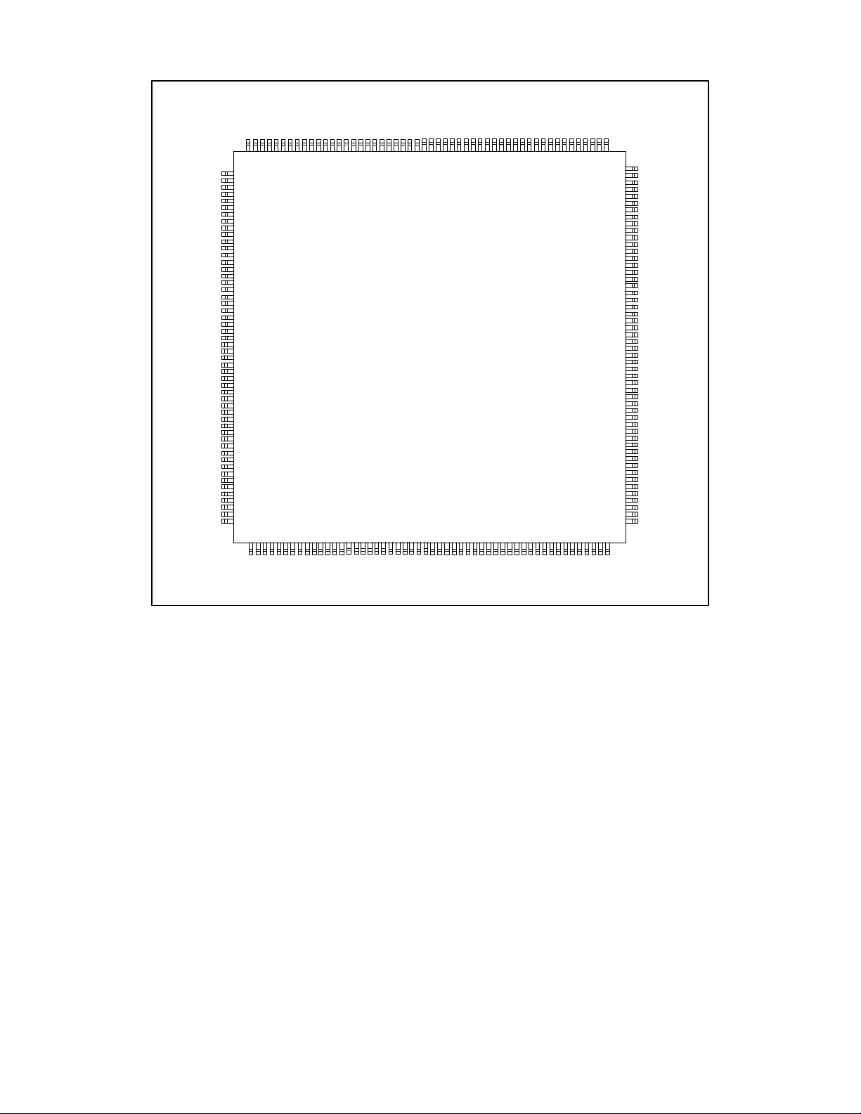
PIN CONFIGURATION
208
207
206
205
204
203
202
201
200
199
198
197
196
195
194
193
192
191
190
189
188
187
186
185
184
183
182
181
180
179
178
177
176
175
174
173
172
171
170
169
168
167
166
165
164
163
162
161
160
159
158
157
N/C
VSSC
VSSC
VDDC
X20
VSSA
BIAS
ZENER
VDDA
RXD2
RXD1
RXD0
CRS
COL
RX_CLK
RX_DV
RX_ER
VDDC
TX_CLK
VSSC
nROMCS
EECS
nRAMOE
nRAMCS
VSSAC
EEDO/MD31
VDDAC
nROMWE
VSSAC
VSSC
VDDC
N/C
MD25
MD19
MD18
MD20
MD15
MD13
MD11
MD14
MD26
MD24
MD17
MD21
MD16
MD23
MD12
MD22
MD30
MD29
MD28
MD27
VSSPC
nPME
VDDIO
VSSPC
VDDIO
VSSA
AD22
AD21
AD20
VSSPC
AD19
AD18
AD17
VDDIO
AD16
nCBE2
VSSPC
nFRAME
nIRDY
VDDIO
VSSC
nTRDY
nDEVSEL
VSSPC
nSTOP
VSSG
nLOCK
VSSIO
VDDC
VSSPC
nPERR
nSERR
VDDIO
PAR
nCBE1
AD15
AD14
VSSPC
AD13
AD12
AD11
AD10
VDDIO
AD9
AD8
VSSC
nCBE0
VSSG
VDDIO
VSSPC
VDDIO
VSSPC
53555657585960616263646566676869707172737475767778798081828384858687888990919293949596979899100
101
102
103
104
54
1
VSSC
VDDC
RXD3
TXD0
TXD1
TXD2
TXD3
VSSC
MDC
MDIO
VDDC
TEST
nINTA
nRST
VDDC
VSSC
VSSG
nGNT
nREQ
AD31
VSSG
AD30
AD29
AD28
AD27
AD26
AD25
AD24
nCBE
IDSEL
AD23
2
3
4
5
6
7
8
9
10
11
12
13
14
15
16
17
18
19
20
21
22
23
24
25
26
27
28
29
30
31
32
33
34
35
36
37
38
39
40
41
42
43
44
45
46
47
48
49
50
51
52
VDDAC
VSSAC
SYSCLK
TX_EN
nPHYRST
n694EN
n694LNK
GPIO1
GPIO2/PHY_INT
PCICLK
nCLKRUN
VDDIO
VSSPC
VDDIO
VDDIO
VSSPC
VSSIO
VSSPC
VDDIO
VSSPC
VDDIO
LAN83C171
208 Pin QFP
156
155
154
153
152
151
150
149
148
147
146
145
144
143
142
141
140
139
138
137
136
135
134
133
132
131
130
129
128
127
126
125
124
123
122
121
120
119
118
117
116
115
114
113
112
111
110
109
108
107
106
105
VDDC
VSSAC
VDDAC
MD10
MD9
MD8
MD7
MD6
MD5
MD/JMP4
MD/JMP3
MD/JMP2
MD/JMP1
MD/JMP0
VSSAC
VDDAC
MA15/nRAMWR
EESK/MA14
EEDI/MA13
MA12
MA11
MA10
VSSC
MA9
MA8
VDDC
VSSAC
VDDAC
MA7
MA6
VSSC
MA5
MA4
MA3
MA2
MA1
MA0
VSSIO
AD0
AD1
VDDIO
AD2
AD3
VSSPC
AD4
AD5
VDDC
AD6
AD7
VDDIO
VSSPC
VDDIO

6
DESCRIPTION OF PIN FUNCTIONS
PQFP PIN NO. NAME I/O TYPE DESCRIPTION
PCI INTERFACE
25
PCICLK I
I
PCLK
,
PCI Clock
dc_lk1
23
nRST I
I
,
PCI
PCI System Reset
dc_lk1
32,36,37,39,40,42,
43,45,49,59-61,
AD I/O
IO
PCI
dc_lk2
,
PCI Multiplexed Address/Data Bus
63-65,67,88,89,
91-94,96,97,108,
109,111,112,114,
115,117,118
46,68,87,99
86
nCBE I/O
PAR I/O
IO
PCI
dc_lk2
IO
PCI
,
PCI Multiplexed Command/Byte
Enable Signals
,
PCI Parity Signal
dc_lk2
70
nFRAME I/O
IO
,
PCI
PCI Cycle Frame Signal
dc_lk2
71
nIRDY I/O
IO
,
PCI
PCI Initiator Ready Signal
dc_lk2
74
nTRDY I/O
IO
,
PCI
PCI Target Ready Signal
dc_lk2
77
nSTOP I/O
IO
,
PCI
PCI Cycle Stop Signal
dc_lk2
79
nLOCK I
IO
,
PCI
PCI Lock Signal
dc_lk2
48
75
IDSEL I
nDEVSEL I/O
I
,
PCI
dc_lk1
IO
PCI
PCI Initiation Device Select Signal.
Used as a Chip Select for
Configuration Reads and Writes
,
PCI Device Select
dc_lk2
31
29
83
nREQ O
nGNT I
nPERR I/O
O
PCI
dc_lk2
I
,
PCI
dc_lk1
IO
PCI
,
PCI Bus Request
PCI Bus Grant
,
PCI Parity Error
dc_lk2
84
nSERR O
O
PCI
dc_lk2
,
PCI System Error (Open Drain)

7
PQFP PIN NO. NAME I/O TYPE DESCRIPTION
22
54
28
nINTA O
nPME O
nCLKRUN I/O
Open
Drain
dc_lk2
Open
Drain
dc_lk2
IO
PCI
PCI Interrupt (Open Drain)
PCI Power Management Event (Open
Drain)
,
PCI Clock Control and Request Line
dc_lk2
EXTERNAL MEMORY INTERFACE
140
139-135,133,132,
128,127,125-120
183,181-162,
153-143
186
185
188
161
187
MA15/nRAMW
R
MA O
MD/JMP I/O
nRAMOE O
nRAMCS O
nROMCS O
nROMWE O
EECS O
O
O
TTL8
dc_lk2
O
TTL8
dc_lk2
IO
TTL2
dc_lk2
O
TTL8
dc_lk2
O
TTL8
dc_lk2
O
TTL4
dc_lk2
O
TTL4
dc_lk2
O
TTL4
dc_lk2
,
Most Significant Address Bit to
Expansion ROM/External RAM Write
Enable
,
Address Bus to Shared RAM and
ROM. (EEDI Muxed Into MA[13],
EESK Muxed Into MA[14]
,
Data Bus to Shared RAM, ROM and
EEPROM (EEDO Input Connected to
MD[31], JMP[4:0] Connected to
MD[4:0])
,
External RAM Output Enable
,
External RAM Chip Select
,
ROM Chip Select and Output Enable
,
External Flash ROM Write Select
,
EEPROM Chip Select
NETWORK INTERFACE
190
TX_CLK I
IO
,
TTL4
MII Transmit Clock
dc_lk2
11
10-7
194
TX_EN O
TXD O
RX_CLK I
O
TTL4
dc_lk2
O
TTL4
dc_lk2
IO
TTL4
,
MII Transmit Enable
,
MII Transmit Data
,
MII Receive Clock
dc_lk2

8
PQFP PIN NO. NAME I/O TYPE DESCRIPTION
196
CRS I
IO
,
TTL4
MII Carrier Sense
dc_lk2
6,199-197
RXD I
IO
,
TTL4
MII Receive Data
dc_lk2
195
COL I
IO
,
TTL4
MII Collision Signal
dc_lk2
193
RX_DV I
IO
,
TTL4
MII Receive Data Valid Signal
dc_lk2
192
RX_ER I
IO
,
TTL4
MII Receive Error Signal
dc_lk2
15
16
MDC O
MDIO I/O
O
TTL4
dc_lk2
IO
TTL4
,
MII Management Interface Clock
,
MII Management Interface Data
dc_lk2
18
13
n694LNK I
n694EN O
10Base-T Link Integrity Status
694 Enable. Tri-States 694 Outputs
when PHY100 is in use
GENERAL PURPOSE
4
20
21
19
204
202
201
12
SYSCLK I
GPIO1 I/O
GPIO2/PHY_INT I/O
TEST I
X20 O
BIAS I
ZENER I
nPHYRST O
I
SCLK System Clock (25 MHz) Input
General Purpose I/O. May also be
used to indicate if the source of power
is the PCI Bus. High(1) to indicate the
power source from PCI bus
General Purpose I/O Can also be used
as a physical layer interrupt. It should
be passively pulled high
I
TTL Used for In-Circuit Device Test
O
,
TTL4
20 MHz Buffered Clock Output
dc_lk2
I
AN Bias Current Input for Clock Multiplier
I
AN Regulated Voltage Input for Clock
Multiplier
Reset Output to Physical Layer Chip
POWER SUPPLY
5,17,24,81,110,131
VDDC PWR
Connect to +5V
,156,158,191,205

9
PQFP PIN NO. NAME I/O TYPE DESCRIPTION
2,129,141,154,182
34,50,72,101,30,
VDDAC PWR
VDDIO PWR
Connect to +5V
Connect to +5V
38,52,55,85,95,
103,105,116,57,66,
107
200
1,14,26,73,98,126,
VDDA PWR
VSSC PWR
Connect to +5V
Connect to Ground
134,159,189,206,
207
3,130,142,155,160,
VSSAC PWR
Connect to Ground
184
27,35,78,100
33,41,47,51,53,56,
VSSG PWR
VSSPC PWR
Connect to Ground
Connect to Ground
62,69,76,82,90,
102,104,106,113
44,80,119
58,203
VSSIO PWR
VSSA PWR
Connect to Ground
Connect to Ground

10
FUNCTIONAL DESCRIPTION
The LAN83C171 EPIC/100 is a high
performance Ethernet network controller
designed to interface directly to the PCI Local
Bus on one side and to the 802.3 standard
Media Independent Interface (MII) on the other
side. The network interface can also be
configured to communicate directly with the
LAN83C694 10BASE-T transceiver.
The LAN83C171 implements 802.3 Media
Access Control functions. It is capable of
running at Ethernet rates of both 100 Mb/s and
10 Mb/s. An MII compliant serial
management interface is provided to control
external media dependent transceivers. The
LAN83C171 is a two channel bus master (one
for transmit, one for receive) capable of
transferring data at the maximum PCI transfer
rate of 132 Mbps. Buffer format in host memory
is controlled by an independent linked list
structure for each channel.
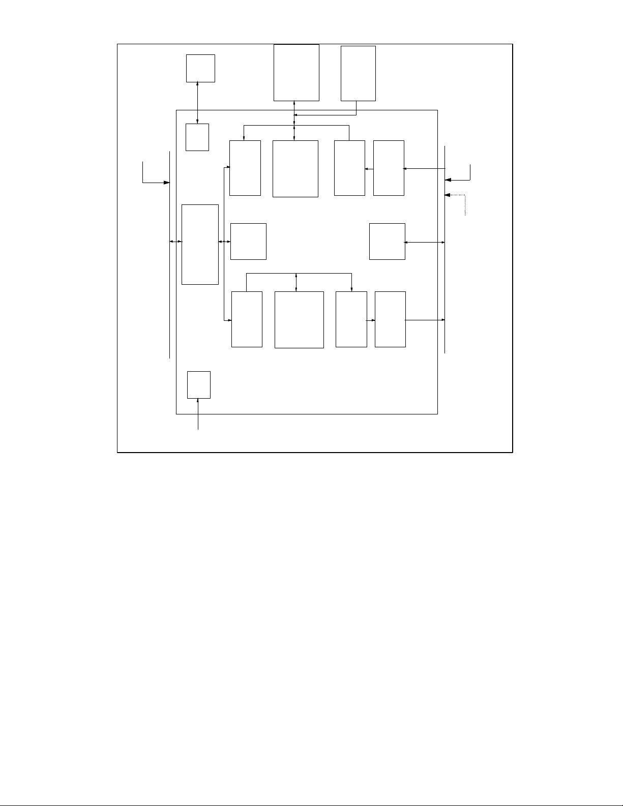
The LAN83C171's architecture is essentially
broken into two independent transmit and
receive processes which share PCI bus and
network bandwidth. This architecture is ideal for
full-duplex networks where transmission and
reception of frames may occur simultaneously.
An internal arbiter controls which process has
access to the PCI bus at a given time (see
section on "transmit/receive arbitration for PCI
bus").
The transmit process consists of a DMA
controller, local transmit RAM, memory transfer
unit ("MTU") and CSMA/CD transmit state
machine. The transmit DMA copies packet data
from host memory into the local buffer. When
ready, the memory transfer unit feeds data from
the transmit buffer to the CSMA/CD state
machine, which is responsible for sending data
out on the network under the Ethernet protocol.
When transmission is complete, the transmit
DMA posts the transmit status into host
memory, interrupts the host (optionally) and
looks for the next transmit packet to be queued.
Like the transmit process, the receive process
consists of a DMA controller, local receive RAM,
memory transfer unit and CSMA/CD state
machine. Packets are received by the
CSMA/CD state machine and stored into local
memory by the receive MTU. The receive DMA
then copies the data from the local buffer into
host memory, posts the receive status and
interrupts the host. The LAN83C171 has several
features designed to minimize CPU utilization,
including the optional Receive Lookahead
Buffering Mode, which eliminates the need to recopy the data from one host memory location to
another. Figure 1 on the following page shows
a block diagram of the LAN83C171.
11
SYS CLOCK
PCI LOCAL BUS
SERIAL
EEPROM
EEPROM
CONTROL
PCI
BUS MASTER
/ SLAVE
INTERFACE
CLOCK
MULT.
PCI
RECEIVE
DMA
4.5 KBytes
REGISTERS
PCI
TRANSMIT
DMA
1.5 KBytes
EXTERNAL
RECEIVE
BUFFER
(OPTIONAL)
INTERNAL
RECEIVE
BUFFER
TRANSMIT BUFFER
BOOT ROM
(OPTIONAL)
RECEIVE
MTU
TRANSMIT
MTU
CSMA/CD
TRANSMIT
MII
MANAGEMENT
CSMA/CD
TRANSMIT
FIGURE 1 - LAN83C171 BLOCK DIAGRAM
MII INTERFACE
LAN83C694
INTERFACE

12
PCI INTERFACE
The transmit and receive DMA controllers
access the PCI bus through the PCI bus
Master/Slave Interface logic. This block is
responsible for requesting the PCI bus and
conducting all bus master operations according
to the PCI bus protocol (including parity
generation and error detection). This block is
also responsible for responding to all slave
operations according to PCI bus protocol
(including address recognition, parity
generation, and error detection).
TRANSMIT/RECEIVE ARBITRATION FOR PCI
BUS
Another major function of the PCI Bus
Master/Slave Interface block is to arbitrate
between the transmit and receive DMA
controllers for access to the PCI bus.
SYSTEM ERRORS
There are four types of PCI bus errors that are
considered fatal by the LAN83C171. They are
Master Abort, Target Abort, Address Parity
Error, and Data Parity Error (see interrupt status
register for details). If any of these errors
occurs, the LAN83C171 will set the appropriate
interrupt and immediately discontinue all DMA
activity. The receiver will automatically be taken
offline and any transmissions in progress will be
completed without a valid CRC appended (in
case transmit data was corrupted). Normal
operation may only be resumed by resetting the
LAN83C171 with the soft reset bit. The software
driver should make sure the transmitter and
receiver have returned to their idle states (by
polling the TXIDLE and RXIDLE bits in the
interrupt status register) before resetting the
device.
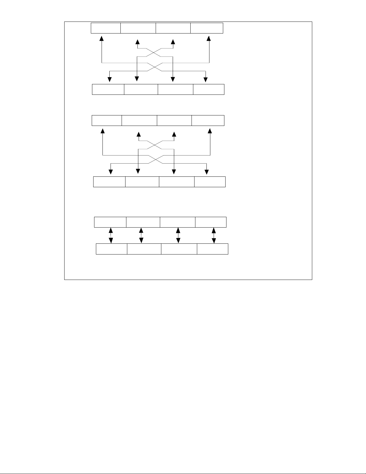
BIG/LITTLE ENDIAN SUPPORT
In order to run in Big Endian machines, the
LAN83C171 can be programmed to swap bytes
on the data bus in certain circumstances. In
Macintosh Power PC computers the bridge
between the Big Endian processor data bus and
the Little Endian PCI bus swaps the order of the
bytes on the data bus (during data phase only addresses are never modified). This means that
byte size quantities transferred over the data
bus always end up in the correct location for
their given address, but when 32 bit (dword)
quantities are transferred they end up with their
bytes reversed.
When programmed into Big Endian mode, the
LAN83C171 automatically swaps the data bytes
internally when reading or writing descriptor
tables or fragment lists. This allows the
software driver to treat the descriptor and
fragment list entries as 32 bit quantities and not
worry about byte ordering.
In order to comply with the PCI specification, the
LAN83C171 does not swap the data bytes on
reads or writes to the configuration or control
register space. The software driver is
responsible for interpreting correctly the bytes
when performing 32 bit register read or writes
on a Big Endian machine.
When reading or writing Ethernet packet data,
the LAN83C171 does not perform any byte
swapping internally because the data on the PCI
bus is already in the correct order.
13
3 2 1 0
31
0
Byte Transfer
Little Endian (PCI) Bus
PCI Bridge Action
0 1 2 3
7 0 7 0 7 0 7 0
Control Register dword transfer:
3 2 1 0
0 1 2 3
7
Descriptor/Fragment list dword transfer:
31 0
0 15 8 23 16 31 24
3 2
0 1 2 3
1 0
Big Endian (PowerPC) Bus
Byte Transfer
Little Endian (PCI) Bus
PCI Bridge Action
Big Endian (PowerPC) Bus
Byte Transfer
Little Endian (PCI) Bus
PCI Bridge Action plus
internal SMC91C120 swap
Big Endian (PowerPC) Bus
FIGURE 2 - LITTLE ENDIAN/BIG ENDIAN BYTE TRANSFER
The number in the box refers to the address of
the byte. The numbers above and below the
boxes refer to the bit number (the bit
ordering increases from LSB to MSB for both
formats although some other documents choose
to label them differently).

14
POWER DOWN MODE
The LAN83C171 has a power down feature
which allows it to consume less power when
not in use. The host may power down the
LAN83C171 by writing a 1 to the power down
bit in the general control register. When the
bit is set, the chip's internal system clock is
gated off to reduce switching current (the
transmit and receive clocks will be shut off
internally if the LAN83C171 is in loopback
mode when power down is set). While the
LAN83C171 is powered down, the host may
read and write the configuration registers or
the general control register. All other
functions are disabled (attempting any other
operation will cause unpredictable behavior).
The power down bit must only be set when the
LAN83C171 is in its idle state.
When the nRST pin is asserted, the
LAN83C171 will automatically enter power
down mode after recalling the contents of the
EEPROM. The host may power up the
LAN83C171 by writing a 0 to the power down
bit. If the host wishes to issue a software
reset to the LAN83C171, the power down bit
must be cleared. When the software reset has
completed, the power down bit will remain
cleared and the LAN83C171 will be ready to
operate.
The power down bit does not affect the PCI
clock inside the LAN83C171. Instead, the
LAN83C171 supports the PCI clock run
function which allows the host system to slow
down or temporarily shut off the PCI clock at
its source. The clock run function is
implemented according to the PCI Mobile
design guide (revision 1.0).
DMA OPERATION
The software driver controls the transmit and
receive DMA controllers through the I/O
control registers and through "buffer
descriptors" in host memory. There is an
independent chain (linked list) of descriptors for
each DMA. Each descriptor may point to a single
data buffer (which can hold a whole frame or
part of a frame) or to a fragment list, which in turn
contains a list of buffers for an entire frame. Each
descriptor also contains control and status
information and a pointer to the next descriptor.
The Descriptors Bit Description section explains
the bits in detail.
TRANSMIT DMA
The software driver initializes the transmit process
by writing the transmit control register, early
transmit threshold register (if early transmit will be
used), interpacket gap program register, interrupt
mask register and general control register. The
software must also program the PCI Transmit
Current Descriptor Address Register (PTCDAR)
with the address in host memory where the first
transmit descriptor will be located.
To begin packet transmissions, the software
driver programs the transmit descriptor chain with
the appropriate number of entries and then sets
the TXQUEUED bit in the COMMAND register.
Under no circumstances should the software
driver set up a circular transmit queue with a
single transmit descriptor pointing to itself. A
minimum of two descriptors is required for proper
EPIC operation.
Descriptor entries describe the location of transmit
data in host memory. Data for a single transmit
frame may not always be in a contiguous block in
host memory. The LAN83C171 allows the
software to specify multiple data buffers for each
frame. Each frame may be queued in one of two
ways, both of which may be used in the same
descriptor chain.
Direct Queuing Method
Descriptors point directly to the transmit data
buffers.

15
One or more descriptors may be used to point
to a single frame. All descriptors must have
the FRAGLIST control bit set to 0. The first
descriptor must contain the transmit length for
the frame. The last descriptor for the frame
must have the LASTDESCR bit set to 1 and
contain the desired values for the TXIAF and
NOCRC control bits. When the TXQUEUED
bit is set, the transmit DMA will read the 4
dword descriptor from the location in host
memory pointed to by its Current Descriptor
Address register. If the ownership bit in the
descriptor is equal to 1 then the LAN83C171
will accept the descriptor and update its
Current Descriptor Address register with the
value in the Next Descriptor Address field.
Otherwise, the TXQUEUED bit will be cleared
(and the transmit queue empty (TQE) interrupt
set) and the Current Descriptor Address
register will not be changed. The Transmit
Length field in the first descriptor will always
contain the number of bytes to be transmitted
on the network, and not necessarily the
number of bytes in the transmit buffers. The
transmit DMA will begin copying data from the
location in host memory specified by the
Buffer Address field in the first descriptor. It
will compare the transmit byte count to the
Data Length field, and copy the lesser number
of bytes into the local transmit RAM. If early
transmit is enabled, the LAN83C171 will
automatically initiate transmission on the
network when the number of bytes specified in
the Early Transmit Threshold register have
been loaded into the transmit buffer.
If the transmit byte count is less than the Data
Length field, or the LASTDESCR bit is set,
then the frame copy is complete after the
buffer has been read. The LAN83C171 will
initiate transmission on the network if it has
not already done so.
If the Data Length field is less than the
transmit byte count and the LASTDESCR bit is
not set, the LAN83C171 will attempt to read
another descriptor. The transmit DMA will
proceed as before, however this time it will not
read the Transmit Length field, but instead use the
remaining number of bytes in its transmit byte
counter (original byte count minus bytes already
copied). This process will continue until a
descriptor is read with the LASTDESCR bit set or
the transmit byte count reaches zero. If
LASTDESCR is set and the total number of bytes
copied do not add up to the transmit byte count,
the transmit MTU will pad the frame with random
data after copying all of the valid data out of the
transmit RAM. The CSMA/CD state machine will
not append the automatically generated CRC to
the frame if NOCRC is set in the last descriptor
for the frame.
After the LAN83C171 has initiated the first
transmission, it will check to see if there are any
more frames in the transmit queue. If the
software does not have another frame ready for
transmission, the ownership bit in the next
descriptor must be 0. If the ownership bit is 0, the
LAN83C171 will clear TXQUEUED and set the
transmit queue empty interrupt. If the ownership
bit is 1, the LAN83C171 will begin copying the
next frame into the local transmit RAM. The DMA
will continue copying transmit buffers until the
frame has been completely loaded into the
transmit RAM or the first transmission has
completed. If the copy completes while the first
transmission is still in progress, the LAN83C171
will stop and wait. When the transmission is
finished, the LAN83C171 will post the status into
the first descriptor for that frame and immediately
initiate the second transmission. If the
transmission completes before the copy is done,
the LAN83C171 will pause after the current
transmit buffer has been copied and post the
status from the first frame. If the early transmit
threshold has already been exceeded then the
second transmission will be initiated immediately.
The transmit DMA will then continue by reading
the next descriptor for the copy in progress.
When the transmit status is posted, the
ownership bit will be written as 0 to indicate that
the host now owns that descriptor again. The

16
Transmit Length field will not be overwritten.
If TXIAF is true in the last descriptor for the
frame, then the transmit complete (TXC)
interrupt will be set. When there are no
frames left in the queue and the last
transmission has completed on the network,
the transmit DMA will set the transmit chain
complete (TCC) interrupt and return to its idle
state.
Note: The difference between the TQE and the
TCC interrupt is that the TQE interrupt is set
only when there are no frames left in the
queue. The TCC interrupt is set only when
there are no frames left in the queue AND the
last frame in the transmit queue buffer has
transmitted. Hence the TQE interrupt is set
first and may or may not be followed by a TCC
interrupt.
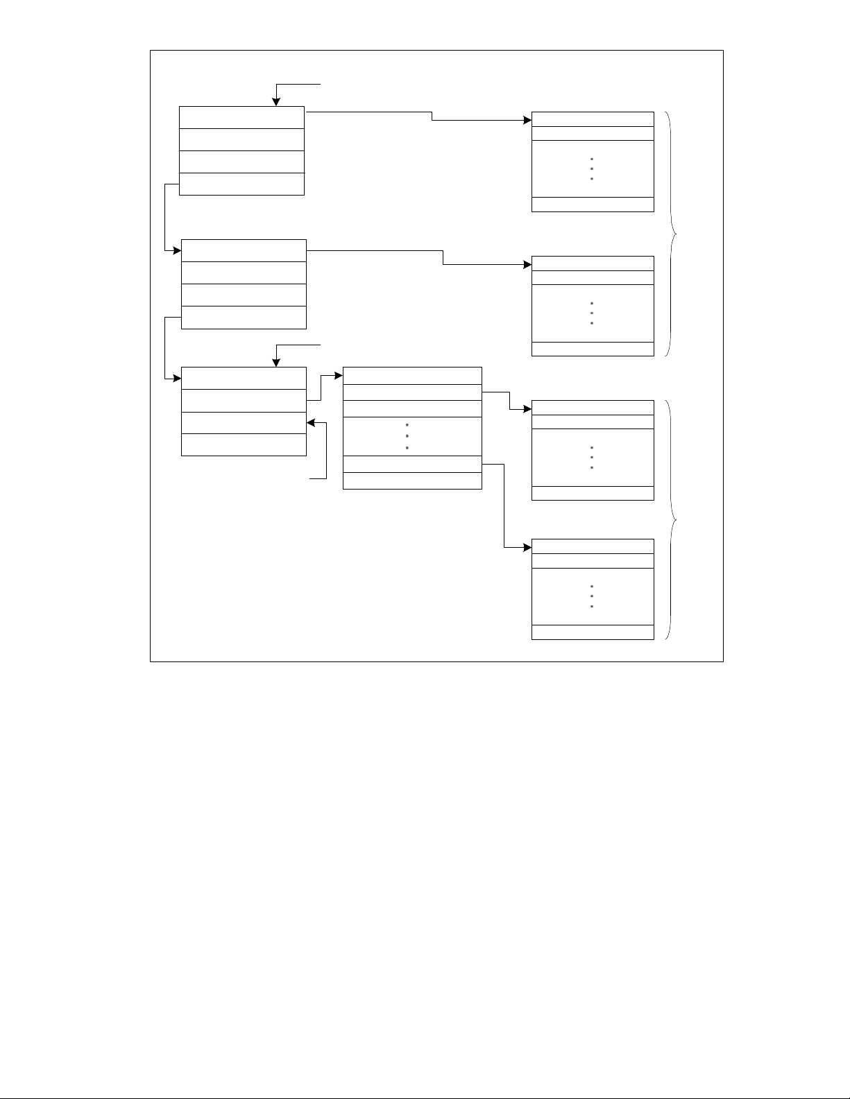
Fragment List Method
Descriptor points to a fragment list.
This method of queuing a transmit frame is
much like the first method, except that each
frame is always specified by one descriptor
which points to a list of buffers (fragment list)
instead of the buffers themselves. The
FRAGLIST bit in the descriptor must be set to
1 and the LFFORM bit must properly indicate
the format of the fragment list. The first entry
in the fragment list tells how many data buffers
(fragments) are listed. Up to 63 fragments are
allowed. The remaining entries specify the
starting address and length of each buffer.
As in the direct queuing method, the transmit
DMA will copy fragments one at a time into the
local buffer until Transmit Length bytes have been
copied or all of the fragments have been read. If
early transmit is enabled, transmission will be
initiated when enough bytes have been copied to
meet the early transmit threshold. Otherwise
transmission will be initiated when the entire copy
is complete.
When more than one frame is queued, the
transmit DMA will begin copying a second frame
while the first is being transmitted. It will continue
copying fragments until the entire frame is loaded
or the first transmission has completed. If the
copy completes while the first transmission is still
in progress, the LAN83C171 will stop and wait.
When the transmission is finished, the
LAN83C171 will post the status into the first
descriptor and immediately initiate the second
transmission. If the transmission completes
before the copy is done, the LAN83C171 will
pause between fragments to post the status and
then resume the copy. If the early transmit
threshold has already been exceeded then the
second transmission will be initiated immediately.
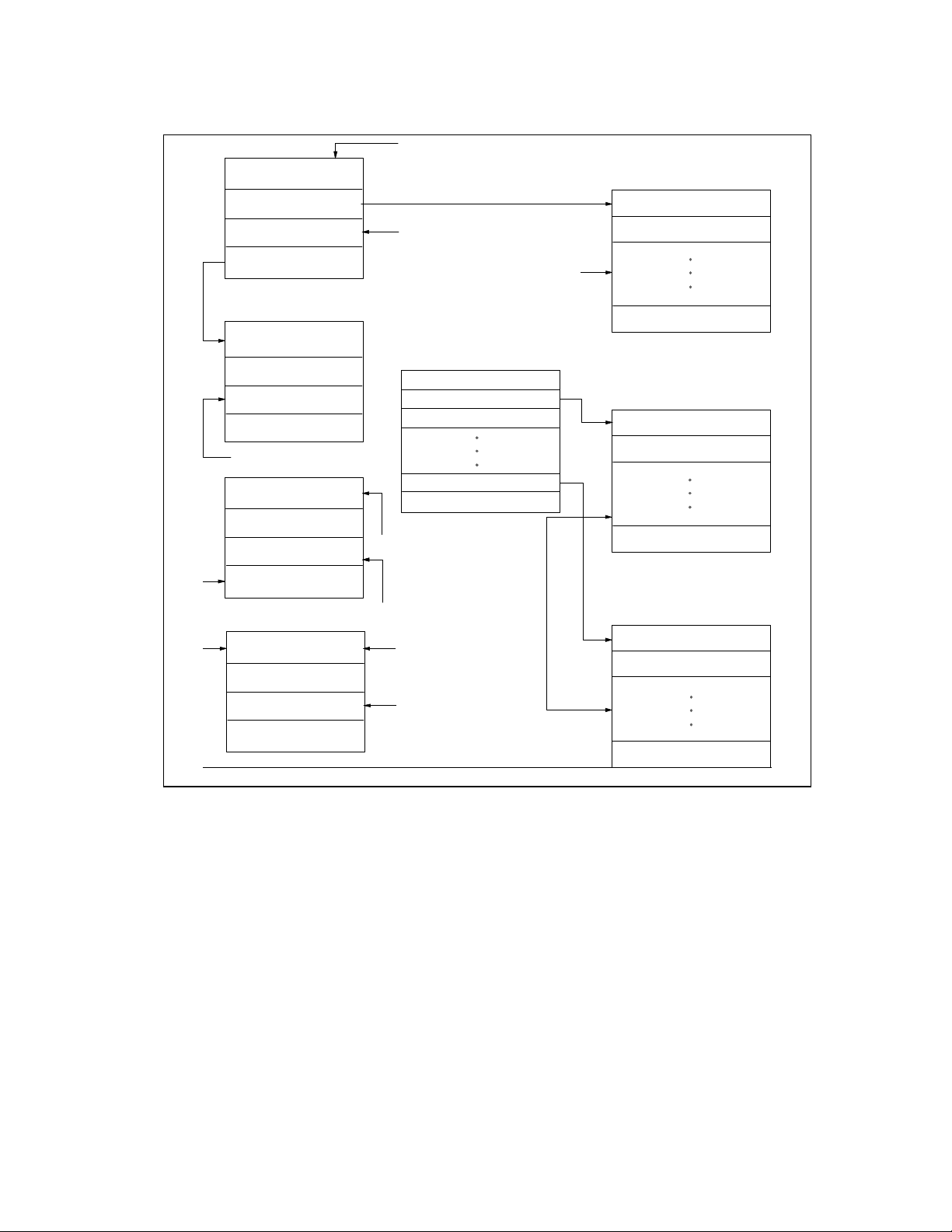
Figure 3 shows a drawing of the Transmit Buffer
Structure.
17
FRAME 1 STATUS
TX LENGTH/STATUS
BUFFER ADDRESS
CONTROL/BUF LENGTH
NEXT DESCR. ADDRESS
TX LENGTH/STATUS
BUFFER ADDRESS
CONTROL/BUF LENGTH
NEXT DESCR. ADDRESS
TX LENGTH/STATUS
BUFFER ADDRESS
CONTROL/BUF LENGTH
NEXT DESCR. ADDRESS
FRAGLIST = 1
FRAME 2 STATUS
NUMBER FRAGS
FRAG1 ADDRESS
FRAGn ADDRESS
FRAGn LENGTH
FRAG1 LENGTH
FRAME DATA
FRAME 1
FRAME DATA
FRAME DATA
LFORM = 0
FRAME 2
FIGURE 3 - TRANSMIT BUFFER STRUCTURE
The software may add transmit frames to the
queue at any time. If the transmit process is
already running (TXQUEUED may still be set)
FRAME DATA
then all of the descriptor and fragment list fields
for the new frame must be valid BEFORE the
ownership bit in the first descriptor is set. After

18
the descriptors are written, the TXQUEUED bit
should be set.
TXQUEUED can be written regardless of
completion status and will ensure that the latest
frame is transmitted. If the LAN83C171
reaches the end of the transmit queue before the
new frame has been added, a transmit chain
complete interrupt is generated for the old
portion of the queue and another transmit chain
complete interrupt will be generated when the
added portion completes.
Interrupting Transmit Chain
The host may interrupt the transmit chain before
all frames have been transmitted by setting the
STOP_TDMA bit in the command register.
Setting this bit forces TXQUEUED to 0. The
transmit DMA will finish copying any frame that
it has already begun, and transmit all frames
that have been loaded into the transmit ram.
After the transmit DMA has posted the status
for the last frame, it will set the transmit chain
complete interrupt and return to its idle state
(exactly as if the next frame in the queue was
owned by the host). If the DMA reads a
descriptor owned by the host while a copy is still
in progress, it will set the transmit queued empty
interrupt and wait for the descriptor to be requeued. It will not return to the idle state until
the copy is completed.
Transmit Buffer Full
Whenever the local transmit RAM becomes full,
the transmit DMA will wait until more space is
available before loading any more data. Space
is freed up as the transmit MTU reads data from
the local RAM and updates its pointers. In
some cases, the transmit MTU will leave its
pointers at the beginning of a frame until it
knows that the transmission will not have to be
retried. Automatic retries can occur due to
collisions or early transmit underruns.
Transmit Underrun
A transmit underrun occurs in early transmit
mode when the transmit DMA cannot keep up
with transmission on the network. Data must be
read from the local RAM before it is available.
Usually, when an underrun occurs, the transmit
MTU will generate a transmit underrun (TXU)
interrupt and update its transmit status register.
The transmit DMA will continue to operate as
though nothing has happened. The software
driver will be allowed to read the transmit status
value from TXSTAT and set the "transmit
underrun go" (TXUGO) bit to tell the MTU to
retry the frame. The MTU will re-transmit the
entire frame out of the local transmit ram. When
transmission has completed successfully, the
DMA will post the transmit status for the retry to
the descriptor for that frame. Operation will
continue as it normally would for a non-underrun
situation.
Exception to Underrun ReTransmission
The only exception to this behavior is when the
transmit MTU cannot automatically retry an
underrun frame. This happens when the frame
size is larger than the transmit RAM (1.5
Kbytes) and the transmit DMA has overwritten
the beginning of the frame before the underrun
occurs. If such an event occurs, the transmit
DMA will abort the copy and reset its pointers to
the first descriptor for that frame. The DMA will
clear the TXQUEUED bit and return to its idle
state. Transmit queue empty and transmit
chain complete interrupts will be generated
along with the transmit underrun interrupt. The
software driver must set TXUGO to reset the
transmit MTU and then set TXQUEUED if it
wants to retry the frame. The frame will be
re-copied from scratch out of host memory
when TXQUEUED is set.
Maximum Transmit Size and Burst Rate
The transmit DMA supports frame sizes up to 64
Kbytes. The maximum size for a single data

19
buffer (fragment) is also 64 Kbytes. The
transmit DMA will run at the maximum PCI data
rate of 132 MByte/sec when the target memory
system supports zero wait state reads. The
transmit DMA will burst as many words as it can
before having to relinquish the PCI bus. It is
capable of bursting data continuously with no
wait states (even when a transmission is active
on the network) until the transmit RAM becomes
full. The transmit DMA, however, will most
likely lose possession of the PCI bus several
times before it can fill the entire 1.5 Kbyte
transmit buffer.
RECEIVE DMA
The software driver initializes the receive
process by writing the receive control register,
interrupt mask register and general control
register. The software must also program the
PCI Receive Current Descriptor Address
Register (PRCDAR) with the address in host
memory where the first receive descriptor will be
located.
To allow packet receptions, the software driver
programs the receive descriptor chain and then
sets the RXQUEUED and START_RX bits in the
COMMAND register. Setting START_RX brings
the CSMA/CD receiver online. The receive DMA
is enabled by setting RXQUEUED. The
software driver should set RXQUEUED before
or simultaneous to bringing the receiver online
so that the receiver does not overflow the local
buffer while waiting for a descriptor to be
queued. The first descriptor must be valid
before the RXQUEUED bit is set. The first
descriptor will be read as soon as it is queued,
even if no receptions have occurred on the
network.
The receive lookahead method offers maximum
performance in most cases.
Free Buffer Pool Method
In this mode the software driver pre-allocates a
pool of free buffers for frames received by the
LAN83C171. The ONECOPY bit in the general
control register must be set so that the each
frame may be copied into the buffer pool without
host intervention. The descriptors for the free
buffer pool may point directly to the buffers, or
point to a fragment list which in turn specifies
the buffers.
When the RXQUEUED bit is set, the receive
DMA will attempt to read the first descriptor
from the address pointed to by its Current
Descriptor Address register. If the ownership bit
is 0, the RXQUEUED bit will be cleared (and the
receive queue empty (RQE) interrupt set) and
the Current Descriptor Address register will not
be changed. If the ownership bit is equal to 1,
the LAN83C171 will accept the descriptor and
update its Current Descriptor Address register
with the value in the Next Descriptor Address
field. The LAN83C171 will save the descriptor
information until a frame is received. If the
fraglist control bit is also 1, then the receive
DMA will read and save the address pointer and
data length for the first buffer in the fragment
list. The offset field in the descriptor (see buffer
length field) should be set to zero, otherwise the
copy will not begin at the start of the frame. The
fragment list format for the receive DMA is
identical to the format for the transmit DMA.
As soon as a frame is received, the LAN83C171
will begin copying it from the local receive
buffer into the allocated buffer in host memory.
If early receive is enabled, the LAN83C171 can
begin the copy while reception is still in
progress. The receive DMA always monitors the
local buffer contents so that a receive underflow
can never occur. As soon as the receive DMA
has copied the number of bytes in the PCI
Receive Copy Threshold register, it will set the
receive copy threshold (RCT) interrupt. When
the receive DMA has copied the entire packet
from the local RAM into host memory, it will

20
post the receive status into the first descriptor
for the frame and set the receive copy complete
(RCC) interrupt. The DMA will read the next
descriptor and, if owned by the NIC, check to
see if there are any more frames to copy out of
the local RAM. If the receive DMA fills the first
host buffer before the entire frame has been
copied, it will read the next descriptor or
fragment list entry to find more buffer space.
This process will continue until the entire frame
has been copied. If the DMA reads a descriptor
with the ownership bit set to 0, it will clear the
RXQUEUED bit (and set the receive queue
empty interrupt) and wait for a new descriptor to
be queued. In fragment list mode, the receive
DMA always expects the fragment list to
contain enough buffer space for the entire
frame.
If all the buffers in the fragment list are filled
before the copy is finished, the DMA will abort
the copy and set the fragment list error bit in the
PRSTAT register. The DMA receive status will
be posted to the descriptor for that frame and
the RXQUEUED bit will be cleared. If early
receive is enabled, the network portion of the
receive status may not be valid yet, as indicated
by the RSV bit posted in the status. The
software driver may poll the RSV bit in the
interrupt status register, and when it returns a 1
read the receive status from PRSTAT. The
software may attempt to re-copy the frame by
setting the RXQUEUED bit again, or may
discard the frame by setting the NEXTFRAME
bit before or simultaneous to setting
RXQUEUED. If RXQUEUED is set after or
along with NEXTFRAME, the DMA will begin to
copy the next frame (if any) in the receive buffer.
Note: The DMA rounds the number of bytes
copied up to the nearest dword. If the receive
buffer does not start on a dword boundary, the
number of bytes in the receive buffer may be
slightly less (up to 3 bytes) than the receive
copy threshold when the interrupt is generated.
Adding Receive Buffers to the Pool
The software driver adds buffers to the pool by
writing the appropriate descriptors and setting
their ownership bit to 1. If the receive DMA has
stopped (RXQUEUED is cleared), the software
must set the RXQUEUED bit to queue the new
descriptors. The RXQUEUED bit may be set at
any time, even if the receive DMA is still active.
Receive Lookahead Method
When this buffering method is used, the
LAN83C171 first copies only the header of a
frame into host memory, and then waits for a
queue from the software driver before copying
the rest of the frame. The software usually
specifies the final destination of the frame data
with a fragment list. The advantage to this
buffering method is that the LAN83C171 may
copy frame data to its final destination instead
of a temporary buffer space, so the software
driver is not required to re-copy the data from
one host memory location to another.
In receive lookahead mode, frames are usually
copied into the host memory one at a time, and
a handshake is performed between the software
driver and the LAN83C171 during each frame.
The handshake is performed using the
RXQUEUED and NEXTFRAME bits in the
COMMAND register, the receive copy complete
(RCC), and header copy complete (HCC)
interrupts. The control bits in the receive
descriptors are also used to direct the receive
DMA.
The software driver begins by setting up a buffer
for the header of the first frame and setting
RXQUEUED. The HEADER control bit in the
descriptor should be set and the FRAGLIST bit
should be cleared. The buffer address pointer
and length are specified directly in the
descriptor. When a frame is received, the
receive DMA begins copying the beginning of
the frame into the header buffer until the buffer
is full, or until the entire frame has been copied.

21
The copy may begin before the entire frame has
been received if early receive is enabled. When
the header copy is complete, the receive DMA
status will then be posted to the descriptor for
the header buffer, and the header copy complete
interrupt will be set. If reception from the
network has completed, the network portion of
the posted status will be valid --and the RSV bit
will be set to 1. In early receive mode, the
receive DMA status may be posted before the
network status for the frame is available, in
which case the RSV bit in the descriptor will be
set to 0. If the entire frame fits into the header
buffer, the network receive status will always be
posted with the frame. After a header copy, the
receive DMA always clears the RXQUEUED bit
(also setting the receive queue empty interrupt,
which may be masked) and waits in the idle
state for the software driver to queue a
fragment list for the rest of the frame.
After examining the header data, the software
driver may discard the frame or have it copied
into host memory as many times as it would
like. The software requests copies of the frame
by programming descriptors (and fragments
lists) and setting RXQUEUED without setting
NEXTFRAME. The frame is copied exactly as it
would be in the free buffer pool mode, with the
exception that the offset field is used with
fragment list copies. The software may not
need all of the bytes at the beginning of the
frame to be copied, so it may specify an offset
into the frame where the copy should begin. The
offset field shares a location in the descriptor
with the buffer length field because the buffer
length is not specified in a descriptor for a
fragment list. The receive DMA copies the frame
into host memory beginning from the byte
number specified in the offset. If the offset field
is not zero, the copy will not begin until the
entire frame has been received from the
network, even if early receive is enabled. This is
so that the receive DMA does not copy invalid
data if the offset is greater than the number of
bytes that have been received so far. Usually,
the entire frame will have been received before
the fragment list is available.
When the copy is finished, the receive status is
posted and the receive copy complete interrupt
is set. The receive DMA will then read the next
descriptor, and if the ownership bit is set it will
immediately begin to copy the same frame into
host memory again. If the descriptor is owned
by the host, RXQUEUED will be cleared (and
receive queue empty interrupt set) and the
receive DMA will wait in the idle state for
another command. If the software driver wants
another copy of the frame, it may queue another
descriptor and set RXQUEUED without setting
NEXTFRAME. This procedure will be repeated
until the software chooses to go on to the next
frame.
The software driver discards a frame by setting
NEXTFRAME before or simultaneous to setting
RXQUEUED. If RXQUEUED is set after or
along with NEXTFRAME, the receive DMA will
begin to copy the next frame (if any) in the
receive buffer. The next descriptor queued
should contain a header buffer for the next
frame.
Occasionally, the software driver may want to
discard a frame immediately after reading its
header, but still read the receive status for that
frame. If the valid network status is not posted
in the descriptor, the software driver may read it
from the PRSTAT register. The driver must set
NEXTFRAME and RXQUEUED to discard the
frame first, as described above. However, the
next descriptor in the receive descriptor list must
have the ownership bit cleared (host still owns
descriptor). This allows the LAN83C171 to
update the PRSTAT register without starting to
copy the following frame. The software driver
must poll the RQE (receive queue empty)
interrupt to determine when the status is
available. When the RQE interrupt is set, the
driver may read the receive status from the
PRSTAT register. The receive status valid bit in

22
the interrupt status register will not indicate
when the receive status is available.
When the software driver wants only one more
copy of the current frame, it does not have to
wait for the copy to complete before setting
NEXTFRAME. The software may set
NEXTFRAME immediately after setting
RXQUEUED (on the following I/O write) and
begin to queue the header descriptor for the next
frame. After the header descriptor is queued, the
software may set RXQUEUED again to
guarantee that the header descriptor is
recognized. When the DMA is finished copying
the first frame, it will immediately read the next
descriptor and may begin copying the next
header without waiting for the software to
respond to an interrupt.
Note: Software must never set NEXTFRAME
more than once per frame.
NEXTFRAME may only be set when
the copy is in progress or has already
been completed.
23
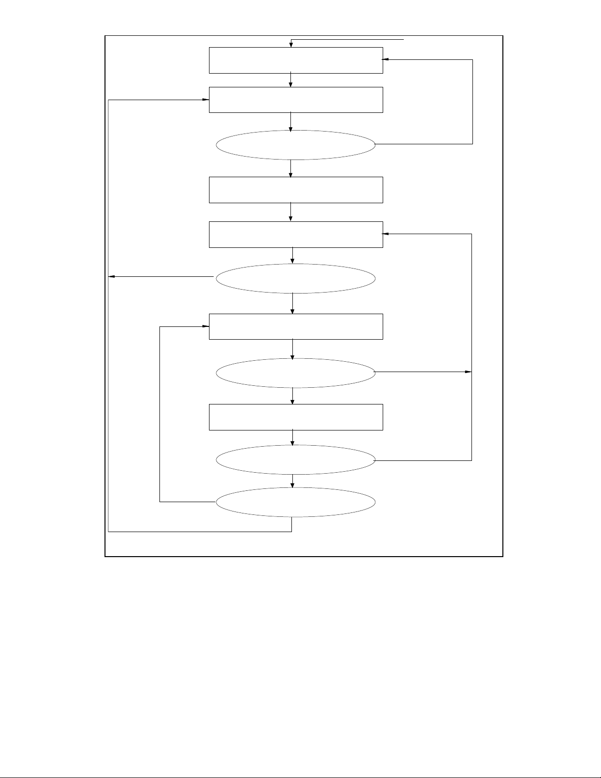
Figure 4 shows an example of the Receive Buffer Structure and also shows a flow
diagram for the Receive Buffering Method.
FRAME 1 STATUS
RX LENGTH/STATUS
BUFFER ADDRESS
CONTROL/BUF LENGTH
NEXT DESCR. ADDRESS
RX LENGTH/STATUS
FRAGLIST ADDRESS
CONTROL/OFFSET
NEXT DESCR. ADDRESS
FRAGLIST = 1
HEADER = 1
FRAME 1 HEADER
NUMBER FRAGS
PTR1(FRAG LENGTH)
FRAG LENGTH(PTR1)
FRAME DATA
FRAME DATA
PTRn(FRAG LENGTHn)
RX LENGTH/STATUS
FRAGLIST ADDRESS
CONTROL/OFFSET
NEXT DESCR. ADDRESS
FRAGLIST = 1
RX LENGTH/STATUS
FRAG LENGTHn(PTRn)
FRAME 1 STATUS/LENGTH
FRAME 2 STATUS/LENGTH
FRAME 1
FRAME DATA
BUFFER ADDRESS
CONTROL/BUF LENGTH
NEXT DESCR. ADDRESS
HEADER = 1
FIGURE 4 - RECEIVE BUFFER STRUCTURE
24
WAIT
READ DESCRIPTOR
OWNER
COPY HEADER
POST STATUS
WAIT
NEXTFRAME
READ DESCRIPTOR
OWNER
COPY FRAME
POST STATUS
RDMA STOPPED
(RXQUEUED=0)
NEXTFRAME
RESET
RXQUEUED SET
HEADER BIT SET
HOST/CLEAR RXQUEUED
GO TO NEXT
FRAME
DONE/CLEAR RXQUEUED SET HCC
RXQUEUED SET
TRUE
FALSE
(HEADER BIT CLEARED)
HOST/CLEAR RXQUEUED
DONE/SET RCC
YES
NO
FALSE
TRUE
NIC
NIC
FIGURE 5 - RECEIVE LOCKAHEAD BUFFERING FLOW

25
Stopping the Receive DMA
The receive DMA may be halted by setting the
STOP_RDMA bit in the command register.
Setting this bit forces RXQUEUED to 0. The
CSMA/CD receiver should also be taken offline
to prevent it from continuing to buffer receive
frames. The receive DMA will attempt to
complete any copy in progress. When finished,
it will return to its idle state. When the
CSMA/CD receiver is offline and has also
returned to its idle state, the RXIDLE bit in the
interrupt status register will become true (1). If
the DMA reads a descriptor owned by the host
before it completes its current copy, it will set
the receive queued empty interrupt and return to
the idle state. The DMA will continue the copy
when more buffers are queued. The software
driver can tell if a copy is still in progress or if
there are any more frames in the local receive
RAM by reading the RCIP and RBE bits in the
interrupt status register.
The STOP_RDMA bit can be set when the
receive DMA has read and saved the
information in a descriptor, but there are no
frames in the local receive RAM. In this case,
the receive DMA will reset its current descriptor
pointer back to that descriptor and return to the
idle state. When the RXQUEUED bit is set
again, the DMA will be re-read the descriptor.
Maximum Receive Size and Burst Rate
The receive DMA supports frame sizes up to 64
Kbytes. The maximum size for a single data
buffer (fragment) is also 64 Kbytes. The receive
DMA will run at the maximum PCI data rate of
132 Mbps when the target memory system
supports zero wait state writes. DMA bursts, at
this rate, will run for a limited number of dwords.
The length of each burst is dependent on the
FIFO threshold level and access to the local
receive RAM. The receive DMA loads data into
the receive burst FIFO at a maximum rate of
100Mb/s (when reception is not in progress) or
83 Mb/s (when reception is in progress). The
receive DMA will automatically initiate a burst on
the PCI bus whenever the FIFO reaches
programmed threshold level. The receive DMA
will continue to load data into the FIFO while it
is being emptied onto the PCI bus. The burst
will continue until the FIFO is empty or the
receive DMA loses control of the PCI bus (to the
internal transmit DMA or to another PCI
master). Another burst will begin when the
FIFO reaches the threshold level again, or when
the last of the data for the current copy has
been loaded into the FIFO. The PCI bus will be
requested immediately if the receive DMA loses
possession of the bus while the FIFO is above
the threshold level.
THR_SEL
[1]
THR_SEL [0] THRESHOLD
LEVEL
0 0 1/4 Full (32
Bytes)
0 1 1/2 Full (64
Bytes)
1 0 3/4 Full (96
Bytes)
1 1 Full (128
Bytes)
A lower threshold allows the LAN83C171 to
begin moving data on the PCI bus sooner, while
a higher threshold may allow longer bursts. A
higher threshold level will not result in longer
data bursts if the receive FIFO never reaches
the empty level (due to latencies on the PCI
bus). The default (reset) threshold level is 1/2
full.

26
MAC OPERATION
The LAN83C171 is compliant with the 802.3
standard CSMA/CD protocol for 10 or 100Mb/s
Ethernet networks.
MAC TRANSMITTER
The LAN83C171 CSMA/CD transmitter is
capable of generating network data at rates of
10 and 100Mb/s. It supports current
implementations of 10Mb/s physical layer
devices, and the 802.3u Media Independent
Interface (MII) for 10 and 100Mb/s.
Basic Function
The transmitter generates serial and nibble
wide data streams at 10 or 100Mb/s. It forms a
proper preamble and SFD field at the beginning
of each packet. The frame data is then shifted
serially or by nibbles from an internal transmit
buffer to the physical layer. The transmitter
completes the packet by computing and
appending the CRC field. During packet
transmission, the transmitter monitors the
network for collisions and retransmits frames
after a random backoff time when necessary.
The transmitter maintains the transmit statistics
and generates status information on each
attempted transmission. Optional operating
modes can be selected by programming the
transmit configuration register.
Preamble Generation
At the beginning of each packet, the transmitter
generates 56 bits of preamble (an alternating
'1010' pattern). Following the preamble, a Start
of Frame Delimiter (a '10101011' sequence) is
transmitted.
Transmit Serializer
The transmit serializer converts 8 bits of parallel
data from the transmit buffer to serial or nibble
wide data. The mode of operation is selected by
the MII configuration register. In serial mode,
the transmit data is shifted out of the TXD[0] pin
synchronous to transmit clock. Data is shifted
out least significant bit (LSB) first. In nibble
mode, data is shifted synchronous to the
transmit clock at a one nibble per clock rate.
The data is transmitted least significant nibble
first on pins TXD[3-0]. The LSB is transmitted
on pin TXD[0].
CRC Generator
The transmitter calculates the CRC and
appends it to each packet. CRC data is clocked
out most significant bit (MSB) first. A packet
can be transmitted without an attached CRC
field by programming the transmit descriptor.
This is provided for bridging applications in
which the original checksum must remain
attached to the packet until the final destination.
Transmit Protocol FSM
The transmit protocol FSM controls the
transmission of packets by monitoring
collisions, deferring to active carriers and
collisions, and initiating backoff when needed.

27
Interframe Gap and Deference
Deference is initiated when both CRS and COL
have terminated at the end of a packet. The
transmitter deference logic initiates a 2-part
timer at the end of network activity. While this
timer is running, no frame transmission will be
initiated. The first part of the timer (interFrame
SpacingPart1) is used to observe the network
for transmission activity by other stations. If this
station is transmitting, carrier is sensed, or
collision is detected during this part of the timer,
the timer will be reset to zero and held there
until the termination of line activity. When the
first part of the timer elapses, line activity is no
longer observed and the timer runs to
completion.
If any frame is queued up for transmission at
the moment of timer expiration, transmission
will be initiated regardless of line activity.
The combination of interFrame SpacingPart1
and interFrame SpacingPart2 makes up the
Inter-Frame Gap (IFG) as defined by the 802.3
specification.
Collision Handling Logic
When collision is detected by the transmitter
section during the first slot timer of an active
transmission, the transmission terminates after
completion of the preamble and the jam
sequence. The jam sequence is 32 bits of logic
'1's. If collision is detected after the slot time is
passed, the transmission will be aborted after
the jam sequence. An out of window collision
interrupt will be generated and the collision
count status will be retained in the transmit
status register for software collection. After the
software has responded to the interrupt and reenabled transmissions, the transmit status will
be cleared and the packet will be automatically
retransmitted.
Timers and Counters/Slot Timer
During transmit, the slot timer starts counting
once the receiver recognizes that a carrier is
present at the start of a returning preamble.
When backing off, the slot timer starts with the
end of transmit enable (TX_EN) for the collided
frame and is not reset by any other incoming
frames. The slot timer is programmable by the
transmit control register. The default slot time is
512 bit times.
Backoff Timer
After a transmission is terminated because of a
collision, a retransmission is attempted. The
backoff time is determined by the truncated
binary exponential backoff algorithm. This
algorithm is:
Draw a random integer r such that r 0<=r<2**k
k is the number of retries already on this
transmission. The value k is initialized to 0.
The required backoff time is 'r' number of slot
times. After the backoff time has been
completed, normal transmission deferral begins.
The backoff timer is a 12 bit counter that is
initialized to a random number when an
attempted transmission results in a collision.
The counter decrements once per slot time until
it reaches zero. The transmit protocol FSM
utilizes this timer to insert a variable amount of
delay ahead of its attempt to retransmit the
frame.
Collision Counter
Prior to the first attempt at each frame
transmission, the collision counter is initialized
to 0. Each attempted transmission of the frame
resulting in a collision causes the collision
counter to increment. If the maximum number
of collisions (16) is reached before a successful
attempt to transmit the frame, the frame
 Loading...