

Page 1
Fan Speed Control with the EMC2102 Device
Insert EVB graphic/photo here
(this text can be removed on master page view)
Copyright © 2007 SMSC or its subsidiaries. All rights reserved.
Circuit diagrams and other information relating to SMSC products are included as a means of illustrating typical applications. Consequently, complete information
sufficient for construction purposes is not necessarily given. Although the information has been checked and is believed to be accurate, no responsibility is assumed
for inaccuracies. SMSC reserves the right to make changes to specifications and product descriptions at any time without notice. Contact your local SMSC sales office
to obtain the latest specifications before placing your product order. The provision of this information does not convey to the purchaser of the described semiconductor
devices any licenses under any patent rights or other intellectual property rights of SMSC or others. All sales are expressly conditional on your agreement to the terms
and conditions of the most recently dated version of SMSC's standard Terms of Sale Agreement dated before the date of your order (the "Terms of Sale Agreement").
The product may contain design defects or errors known as anomalies which may cause the product's functions to deviate from published specifications. Anomaly
sheets are available upon request. SMSC products are not designed, intended, authorized or warranted for use in any life support or other application where product
failure could cause or contribute to personal injury or severe property damage. Any and all such uses without prior written approval of an Officer of SMSC and further
testing and/or modification will be fully at the risk of the customer. Copies of this document or other SMSC literature, as well as the Terms of Sale Agreement, may be
obtained by visiting SMSC’s website at http://www.smsc.com. SMSC is a registered trademark of Standard Microsystems Corporation (“SMSC”). Product names and
company names are the trademarks of their respective holders.
SMSC DISCLAIMS AND EXCLUDES ANY AND ALL WARRANTIES, INCLUDING WITHOUT LIMITATION ANY AND ALL IMPLIED WARRANTIES OF
MERCHANTABILITY, FITNESS FOR A PARTICULAR PURPOSE, TITLE, AND AGAINST INFRINGEMENT AND THE LIKE, AND ANY AND ALL WARRANTIES
ARISING FROM ANY COURSE OF DEALING OR USAGE OF TRADE. IN NO EVENT SHALL SMSC BE LIABLE FOR ANY DIRECT, INCIDENTAL, INDIRECT,
SPECIAL, PUNITIVE, OR CONSEQUENTIAL DAMAGES; OR FOR LOST DATA, PROFITS, SAVINGS OR REVENUES OF ANY KIND; REGARDLESS OF THE
FORM OF ACTION, WHETHER BASED ON CONTRACT; TORT; NEGLIGENCE OF SMSC OR OTHERS; STRICT LIABILITY; BREACH OF WARRANTY; OR
OTHERWISE; WHETHER OR NOT ANY REMEDY OF BUYER IS HELD TO HAVE FAILED OF ITS ESSENTIAL PURPOSE, AND WHETHER OR NOT SMSC HAS
BEEN ADVISED OF THE POSSIBILITY OF SUCH DAMAGES.
SMSC EMC2102 USER MANUAL Revision 0.2 (09-17-07)
Page 2

Fan Speed Control with the EMC2102 Device
Table of Contents
1 Overview . . . . . . . . . . . . . . . . . . . . . . . . . . . . . . . . . . . . . . . . . . . . . . . . . . . . . . . . . . . . . . 6
2 Audience . . . . . . . . . . . . . . . . . . . . . . . . . . . . . . . . . . . . . . . . . . . . . . . . . . . . . . . . . . . . . . 6
3 References . . . . . . . . . . . . . . . . . . . . . . . . . . . . . . . . . . . . . . . . . . . . . . . . . . . . . . . . . . . . . 6
4 The Evaluation System. . . . . . . . . . . . . . . . . . . . . . . . . . . . . . . . . . . . . . . . . . . . . . . . . . . 6
5 Basic Operation Experiments . . . . . . . . . . . . . . . . . . . . . . . . . . . . . . . . . . . . . . . . . . . . . 8
5.1 Experiment 1 - Manual Fan Control . . . . . . . . . . . . . . . . . . . . . . . . . . . . . . . . . . . . . . . . . . . . . . . . . 8
5.1.1 ChipMan Installation . . . . . . . . . . . . . . . . . . . . . . . . . . . . . . . . . . . . . . . . . . . . . . . . . . . . . 8
5.1.2 Setting Up the ChipMan . . . . . . . . . . . . . . . . . . . . . . . . . . . . . . . . . . . . . . . . . . . . . . . . . . 8
5.1.3 Plotting From ChipMan . . . . . . . . . . . . . . . . . . . . . . . . . . . . . . . . . . . . . . . . . . . . . . . . . . 12
5.2 Experiment 2 - RPM Based Closed-Loop Fan Control. . . . . . . . . . . . . . . . . . . . . . . . . . . . . . . . . . 13
5.2.1 Getting Started . . . . . . . . . . . . . . . . . . . . . . . . . . . . . . . . . . . . . . . . . . . . . . . . . . . . . . . . 13
5.2.2 Basic RPM Based Fan Control . . . . . . . . . . . . . . . . . . . . . . . . . . . . . . . . . . . . . . . . . . . . 14
5.2.3 Effects of Loading . . . . . . . . . . . . . . . . . . . . . . . . . . . . . . . . . . . . . . . . . . . . . . . . . . . . . . 14
5.2.4 Register Change Summary . . . . . . . . . . . . . . . . . . . . . . . . . . . . . . . . . . . . . . . . . . . . . . . 15
5.3 Experiment 3 - Spin-up Configuration Options . . . . . . . . . . . . . . . . . . . . . . . . . . . . . . . . . . . . . . . . 16
5.3.1 Fan Control Parameters . . . . . . . . . . . . . . . . . . . . . . . . . . . . . . . . . . . . . . . . . . . . . . . . . 16
5.3.2 Getting Started . . . . . . . . . . . . . . . . . . . . . . . . . . . . . . . . . . . . . . . . . . . . . . . . . . . . . . . . 17
5.3.3 Forced Kick Function. . . . . . . . . . . . . . . . . . . . . . . . . . . . . . . . . . . . . . . . . . . . . . . . . . . . 17
5.3.4 Spin-Up Level . . . . . . . . . . . . . . . . . . . . . . . . . . . . . . . . . . . . . . . . . . . . . . . . . . . . . . . . . 17
5.3.5 Spin-Up Time. . . . . . . . . . . . . . . . . . . . . . . . . . . . . . . . . . . . . . . . . . . . . . . . . . . . . . . . . . 18
5.3.6 Register Change Summary . . . . . . . . . . . . . . . . . . . . . . . . . . . . . . . . . . . . . . . . . . . . . . . 19
5.4 Experiment 4 - RPM Drive Mode Rate Controls. . . . . . . . . . . . . . . . . . . . . . . . . . . . . . . . . . . . . . . 20
5.4.1 General Setup . . . . . . . . . . . . . . . . . . . . . . . . . . . . . . . . . . . . . . . . . . . . . . . . . . . . . . . . . 20
5.4.2 Controlling the Ramp Rate . . . . . . . . . . . . . . . . . . . . . . . . . . . . . . . . . . . . . . . . . . . . . . . 20
5.4.3 Register Change Summary . . . . . . . . . . . . . . . . . . . . . . . . . . . . . . . . . . . . . . . . . . . . . . . 22
5.5 Experiment 5 - Optimizing RPM Control Response . . . . . . . . . . . . . . . . . . . . . . . . . . . . . . . . . . . . 23
5.5.1 General Setup . . . . . . . . . . . . . . . . . . . . . . . . . . . . . . . . . . . . . . . . . . . . . . . . . . . . . . . . . 23
5.5.2 Fan Configuration Register (52h) . . . . . . . . . . . . . . . . . . . . . . . . . . . . . . . . . . . . . . . . . . 23
5.5.3 FAN Minimum Drive Register (55h) and Valid TACH Count (56h) . . . . . . . . . . . . . . . . . 24
5.5.4 Register Change Summary . . . . . . . . . . . . . . . . . . . . . . . . . . . . . . . . . . . . . . . . . . . . . . . 25
5.6 Experiment 6 - Limits and Alerts. . . . . . . . . . . . . . . . . . . . . . . . . . . . . . . . . . . . . . . . . . . . . . . . . . . 26
5.6.1 General Setup . . . . . . . . . . . . . . . . . . . . . . . . . . . . . . . . . . . . . . . . . . . . . . . . . . . . . . . . . 26
5.6.2 Fan Spin and Stall Interrupts. . . . . . . . . . . . . . . . . . . . . . . . . . . . . . . . . . . . . . . . . . . . . . 26
5.6.3 Register Change Summary . . . . . . . . . . . . . . . . . . . . . . . . . . . . . . . . . . . . . . . . . . . . . . . 27
5.7 Experiment 7 - Troubleshooting . . . . . . . . . . . . . . . . . . . . . . . . . . . . . . . . . . . . . . . . . . . . . . . . . . . 28
5.7.1 Repetitious Spin-up Routine Caused by Incorrect Settings. . . . . . . . . . . . . . . . . . . . . . . 28
6 Appendix . . . . . . . . . . . . . . . . . . . . . . . . . . . . . . . . . . . . . . . . . . . . . . . . . . . . . . . . . . . . . 35
6.1 DC Fan Basics - Poles, Tach Meter Pulses and Edges . . . . . . . . . . . . . . . . . . . . . . . . . . . . . . . . . 35
6.2 Characterizing a DC Fan with EVB-EMC2102 and ChipMan. . . . . . . . . . . . . . . . . . . . . . . . . . . . . 36
6.2.1 General Setup . . . . . . . . . . . . . . . . . . . . . . . . . . . . . . . . . . . . . . . . . . . . . . . . . . . . . . . . . 36
6.2.2 Set the Correct LIMIT2K Value . . . . . . . . . . . . . . . . . . . . . . . . . . . . . . . . . . . . . . . . . . . . 37
6.2.3 Determine the Number of Poles and the Maximum Fan Speed . . . . . . . . . . . . . . . . . . . 37
6.2.4 Determine the Minimum Startup Speed. . . . . . . . . . . . . . . . . . . . . . . . . . . . . . . . . . . . . . 37
6.2.5 Determine the Stall Speed. . . . . . . . . . . . . . . . . . . . . . . . . . . . . . . . . . . . . . . . . . . . . . . . 37
6.2.6 Determine the Minimum Valid TACH Speed . . . . . . . . . . . . . . . . . . . . . . . . . . . . . . . . . . 37
6.2.7 Determine the Spin-up Levels (rpm60 and rpm75) . . . . . . . . . . . . . . . . . . . . . . . . . . . . . 38
Revision 0.2 (09-17-07)
USER MANUAL SMSC EMC2102
2
Page 3

Fan Speed Control with the EMC2102 Device
6.2.8 Using the Tested Parameters . . . . . . . . . . . . . . . . . . . . . . . . . . . . . . . . . . . . . . . . . . . . . 38
SMSC EMC2102
USER MANUAL Revision 0.2 (09-17-07)
3
Page 4

Fan Speed Control with the EMC2102 Device
List of Figures
Figure 4.1 EMC2102 Fan Control Evaluation System. . . . . . . . . . . . . . . . . . . . . . . . . . . . . . . . . . . . . . . . 7
Figure 4.2 EVB-EMC2102 Board . . . . . . . . . . . . . . . . . . . . . . . . . . . . . . . . . . . . . . . . . . . . . . . . . . . . . . . 7
Figure 5.1 ChipMan Message for First Operation. . . . . . . . . . . . . . . . . . . . . . . . . . . . . . . . . . . . . . . . . . . 8
Figure 5.2 ChipMan Device Selection Window. . . . . . . . . . . . . . . . . . . . . . . . . . . . . . . . . . . . . . . . . . . . . 9
Figure 5.3 Selecting the Device and Master Controller Type . . . . . . . . . . . . . . . . . . . . . . . . . . . . . . . . . 10
Figure 5.4 ChipMan Operation Window . . . . . . . . . . . . . . . . . . . . . . . . . . . . . . . . . . . . . . . . . . . . . . . . . 10
Figure 5.5 Changing Fan Speed. . . . . . . . . . . . . . . . . . . . . . . . . . . . . . . . . . . . . . . . . . . . . . . . . . . . . . . 12
Figure 5.6 Plotting from the ChipMan . . . . . . . . . . . . . . . . . . . . . . . . . . . . . . . . . . . . . . . . . . . . . . . . . . . 12
Figure 5.8 Plot Examples . . . . . . . . . . . . . . . . . . . . . . . . . . . . . . . . . . . . . . . . . . . . . . . . . . . . . . . . . . . . 13
Figure 5.7 Plot Windows . . . . . . . . . . . . . . . . . . . . . . . . . . . . . . . . . . . . . . . . . . . . . . . . . . . . . . . . . . . . . 13
Figure 5.9 Plots for Proper Control Settings . . . . . . . . . . . . . . . . . . . . . . . . . . . . . . . . . . . . . . . . . . . . . . 14
Figure 5.10 Effects of Loading . . . . . . . . . . . . . . . . . . . . . . . . . . . . . . . . . . . . . . . . . . . . . . . . . . . . . . . . . 15
Figure 5.11 Fan Control Parameters. . . . . . . . . . . . . . . . . . . . . . . . . . . . . . . . . . . . . . . . . . . . . . . . . . . . . 16
Figure 5.12 Forced Kick Function . . . . . . . . . . . . . . . . . . . . . . . . . . . . . . . . . . . . . . . . . . . . . . . . . . . . . . . 17
Figure 5.13 60% Spin Level Setting . . . . . . . . . . . . . . . . . . . . . . . . . . . . . . . . . . . . . . . . . . . . . . . . . . . . . 18
Figure 5.14 Reduced Spin-up Time . . . . . . . . . . . . . . . . . . . . . . . . . . . . . . . . . . . . . . . . . . . . . . . . . . . . . 18
Figure 5.15 Default Ramp Rate. . . . . . . . . . . . . . . . . . . . . . . . . . . . . . . . . . . . . . . . . . . . . . . . . . . . . . . . . 20
Figure 5.16 Default Step Size with Different UPDATE Settings . . . . . . . . . . . . . . . . . . . . . . . . . . . . . . . . 21
Figure 5.17 Default UPDATE with Different Step Size Settings . . . . . . . . . . . . . . . . . . . . . . . . . . . . . . . . 21
Figure 5.18 Exceptionally Slow Rate. . . . . . . . . . . . . . . . . . . . . . . . . . . . . . . . . . . . . . . . . . . . . . . . . . . . . 22
Figure 5.19 Update Time Modifications. . . . . . . . . . . . . . . . . . . . . . . . . . . . . . . . . . . . . . . . . . . . . . . . . . . 23
Figure 5.20 Minimum Drive Setting. . . . . . . . . . . . . . . . . . . . . . . . . . . . . . . . . . . . . . . . . . . . . . . . . . . . . . 24
Figure 5.21 Valid Tach Count Setting . . . . . . . . . . . . . . . . . . . . . . . . . . . . . . . . . . . . . . . . . . . . . . . . . . . . 24
Figure 5.22 Fan Spin and Stall . . . . . . . . . . . . . . . . . . . . . . . . . . . . . . . . . . . . . . . . . . . . . . . . . . . . . . . . . 27
Figure 5.23 Fan Spin-up Routine Restarted Repeatedly . . . . . . . . . . . . . . . . . . . . . . . . . . . . . . . . . . . . . 28
Figure 5.24 Theoretical Plot of Case 1 . . . . . . . . . . . . . . . . . . . . . . . . . . . . . . . . . . . . . . . . . . . . . . . . . . . 29
Figure 5.25 Spin-up Case 1 Fix 1 . . . . . . . . . . . . . . . . . . . . . . . . . . . . . . . . . . . . . . . . . . . . . . . . . . . . . . . 29
Figure 5.26 Spin-up Case 1 Fix 2 . . . . . . . . . . . . . . . . . . . . . . . . . . . . . . . . . . . . . . . . . . . . . . . . . . . . . . . 30
Figure 5.27 Theoretical Plot of Case 2 . . . . . . . . . . . . . . . . . . . . . . . . . . . . . . . . . . . . . . . . . . . . . . . . . . . 30
Figure 5.28 Spin-up Case 2 . . . . . . . . . . . . . . . . . . . . . . . . . . . . . . . . . . . . . . . . . . . . . . . . . . . . . . . . . . . 31
Figure 5.29 Theoretical Plot of Case 3 . . . . . . . . . . . . . . . . . . . . . . . . . . . . . . . . . . . . . . . . . . . . . . . . . . . 31
Figure 5.30 Spin-up Case 3 . . . . . . . . . . . . . . . . . . . . . . . . . . . . . . . . . . . . . . . . . . . . . . . . . . . . . . . . . . . 32
Figure 5.31 Spin-up Routine Restarted During Normal Operation . . . . . . . . . . . . . . . . . . . . . . . . . . . . . . 32
Figure 5.32 Theoretical Plot of Case 4 . . . . . . . . . . . . . . . . . . . . . . . . . . . . . . . . . . . . . . . . . . . . . . . . . . . 33
Figure 5.33 Spin-up Case 4 . . . . . . . . . . . . . . . . . . . . . . . . . . . . . . . . . . . . . . . . . . . . . . . . . . . . . . . . . . . 33
Figure 5.34 Spin-up Case 5 . . . . . . . . . . . . . . . . . . . . . . . . . . . . . . . . . . . . . . . . . . . . . . . . . . . . . . . . . . . 34
Figure 5.35 Spin-up Case 5 Fix. . . . . . . . . . . . . . . . . . . . . . . . . . . . . . . . . . . . . . . . . . . . . . . . . . . . . . . . . 34
Figure 6.1 A Typical 2-pole DC Fan . . . . . . . . . . . . . . . . . . . . . . . . . . . . . . . . . . . . . . . . . . . . . . . . . . . . 35
Figure 6.2 Output Signal of a 2-pole Fan . . . . . . . . . . . . . . . . . . . . . . . . . . . . . . . . . . . . . . . . . . . . . . . . 35
Figure 6.3 Fan TACH Measurement With EMC2102 . . . . . . . . . . . . . . . . . . . . . . . . . . . . . . . . . . . . . . . 36
Revision 0.2 (09-17-07)
USER MANUAL SMSC EMC2102
4
Page 5

Fan Speed Control with the EMC2102 Device
List of Tables
Table 5.1 Register Change Summary for Experiment 2 . . . . . . . . . . . . . . . . . . . . . . . . . . . . . . . . . . . . . 15
Table 5.2 Register Change Summary for Experiment 3 . . . . . . . . . . . . . . . . . . . . . . . . . . . . . . . . . . . . . 19
Table 5.3 Register Change Summary for Experiment 4 . . . . . . . . . . . . . . . . . . . . . . . . . . . . . . . . . . . . . 22
Table 5.4 Register Change Summary for Experiment 7 . . . . . . . . . . . . . . . . . . . . . . . . . . . . . . . . . . . . . 25
SMSC EMC2102
USER MANUAL Revision 0.2 (09-17-07)
5
Page 6

1 Overview
SMSC has introduced a series of Environmental Monitoring and Control (EMC) device s with integrated
fan control. This fan controller family devices feature the advanced closed-loop fan control technology
developed by SMSC’s engineering team.
This user manual provides detailed information about fan control features supported by one of those
EMC devices -- EMC2102, with detailed hand-on experiments for configuring the devices in real
applications.
2 Audience
This user manual assumes that the reader is familiar with the functionality of the EMC2102 device and
its evaluation board. The goal of the user manual is to help users to evaluate the new EMC device
using Chip Manager (ChipMan) software provided by SMSC. This user manual also can be used as a
reference material for other EMC devices which have fan control features.
3 References
The following documents should be referenced when using this user manual:
EMC2102 Device Datasheet
EVB-EMC2102 Evaluation Board User Manual
EVB-EMC2102 Evaluation Board Schematics
ChipMan Software User Manual
Fan Speed Control with the EMC2102 Device
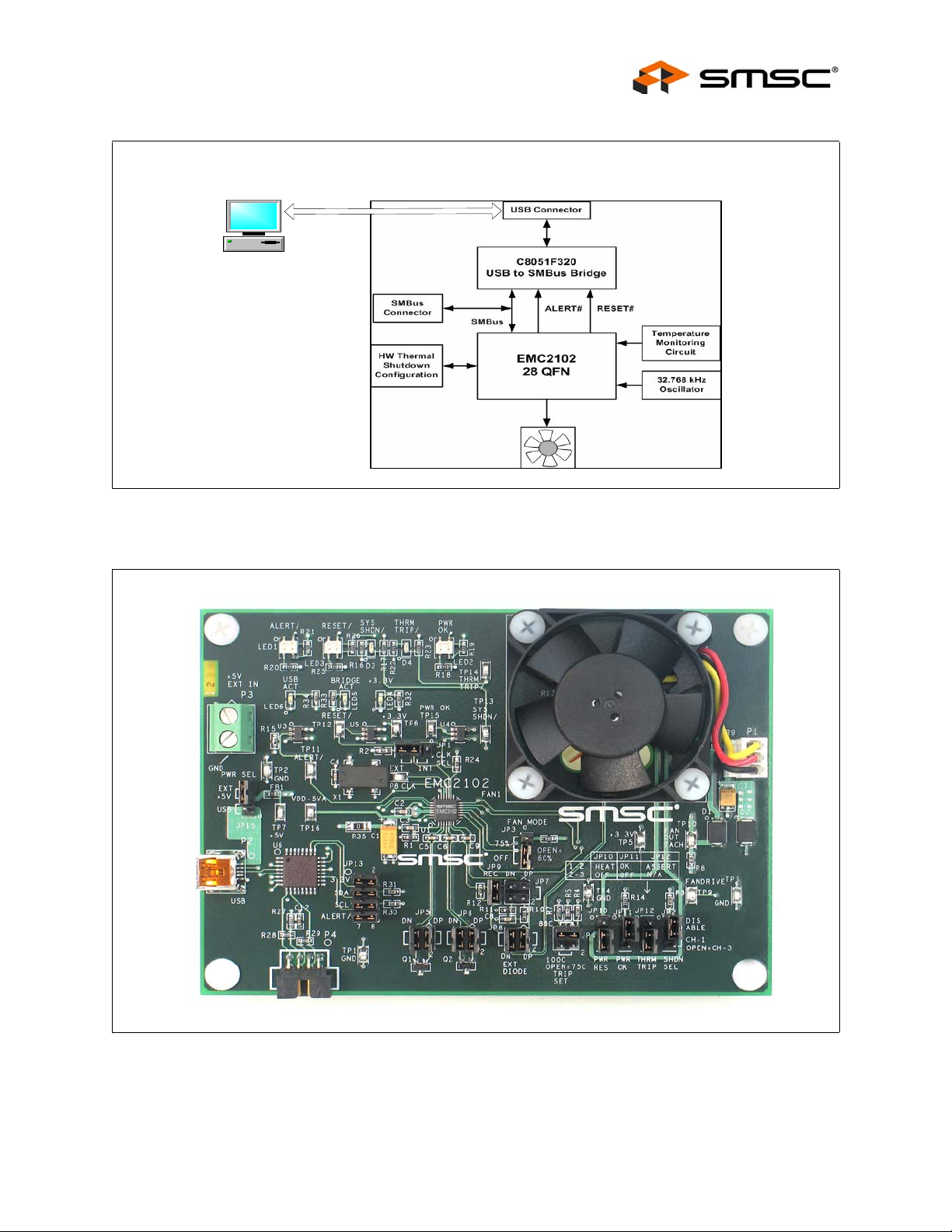
4 The Evaluation System
The evaluation system used for this user manual has two major parts, as shown in Figure 4.1,
"EMC2102 Fan Control Evaluation System":
An EMC2102 evaluation board (EVB-EMC2102) with on-board 5V DC fan (Figure 4.2)
A PC with SMSC ChipMan software installed (requiring XML file for EMC2102 device)
This user manual contains several groups of user experiments which cover most of the fan control
features of the EMC2102 fan controller device. All examples are based on the 2102 device evaluation
board (EVB-EMC2102) and its software, but the methods and the results will apply to other EMC2102
applications.
Revision 0.2 (09-17-07)
USER MANUAL SMSC EMC2102
6
Page 7
Fan Speed Control with the EMC2102 Device
PC w/ ChipMan Software
Figure 4.1 EMC2102 Fan Control Evaluation System
USB Cable
EVB-EMC2102
SMSC EMC2102
Figure 4.2 EVB-EMC2102 Board
USER MANUAL Revision 0.2 (09-17-07)
7
Page 8
5 Basic Operation Experiments
In this chapter basic operation experiments will be provided to help users to get familiar with the
system.
5.1 Experiment 1 - Manual Fan Control
This experiment is designed to gain familiarity with both the EMC2102 device, and the application
software, ChipMan.
The ChipMan application can be used to configure the EMC2102 devi ce and to monitor the status of
the device. It includes tools to capture and plot data at rates up to 10Hz. Additionally, ChipMan can
be used to review previously saved data.
5.1.1 ChipMan Installation
Install the ChipMan application and device driver on a PC by running Setup.exe from the EMC2102
Evaluation System Software CD provided by SMSC. A revision history and install/uninstall notes may
be found in the readme.txt file on the disk.
ChipMan uses definition files and data files to identify the devices it supports, to load specific values
into registers, and monitor, plot, or record the values of any register set in the device. ChipMan
definition files are XML files conforming to XML Version="1.0" and Encoding="utf-8". The data files for
downloading values to the device are CMF files, specific to the ChipMa n application.
Fan Speed Control with the EMC2102 Device
The CMF files may be located anywhere on the hard drive, but the XML files MUST reside in the
ChipMan directory, typically located at: C:\Program Files\SMSC\ChipMan\Chips. An XML file usually
names with the device name that supports (EMC2102.xml, EMC2103-2.xml, etc.)
During the installation of the ChipMan application, it is possible to specify a non-default installation
directory. If this was done, substitute the path provided at that installation for "C:\Program Files" to
store the XML files in the proper location.
Connect the USB cable to an available USB port on the PC, (The o ther end, “mini-B” end, of the USB
cable should be connected to an EMC Evaluation Board). The “Find New Hardware” wizard will pop
up on the PC’s screen for USB driver installation. Follow the instructions on the screen to complete
the installation process.
5.1.2 Setting Up the ChipMan
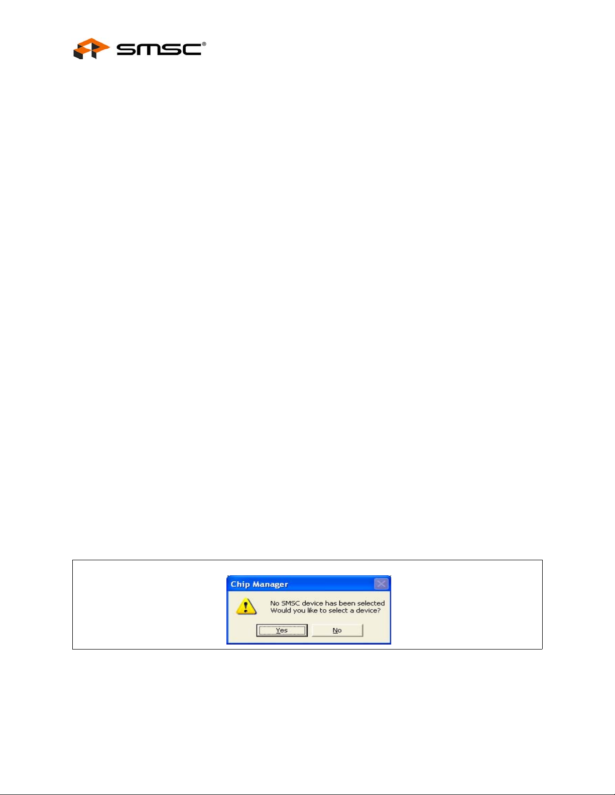
Once the ChipMan has been installed, start the software by selecting Start -> Programs -> SMSC ->
Chip Manager. If this is the first operation, the application will guide you to select a device, as shown
in Figure 5.1 below.
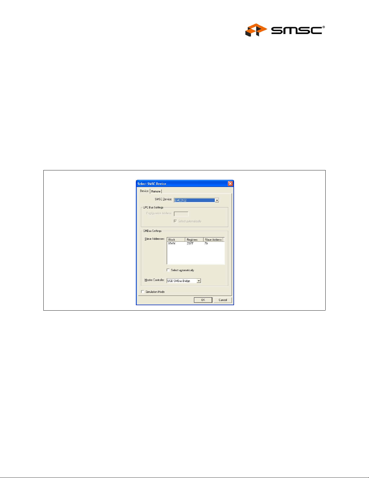
Answer "Yes", then the device selection menu as shown in Figure 5.2, "ChipMan Device Selection
Window" will appear.
Click on the Pull-Down menu at the top, select EMC2102 as shown in Figure 5.3, "Selecting the Device
and Master Controller Type", and click OK. The ChipMan operation window will then appear, as shown
Revision 0.2 (09-17-07)
Figure 5.1 ChipMan Message for First Operation
USER MANUAL SMSC EMC2102
8
Page 9
Fan Speed Control with the EMC2102 Device
in Figure 5.4, "ChipMan Operation Window". Click on the HWM icon to show the different windows
available.
The EMC2102 WatchDog will have timed out at this point, and the on-board DC fan will be running at
100%.
Note: Starting the ChipMan application without the USB cable/EVB connected to the PC, an error
message "Supported company ID on device not found" will pop-up. Plug in the USB cable a nd
click on “Abort”, another pop-up window will ask if you want to select an SMSC device. Click
on “Yes” and then select the device as shown in Figure 5.3.
In the same device selection window the user al so has the options to chose the SMBus Slave Address
(Default is 7A for EVB-EMC2102, use “Select automatically” is recommended), the Master Controller
type (Default is USB SMBus Bridge, see note 1 be low) and if the ChipMan needs to be configured to
run in simulation mode. In the simulation mode, users can practice the software functions without
connecting a USB cable/EVB to the PC.
For more help with ChipMan, select Help -> Contents for an html based help documen t.
SMSC EMC2102
Figure 5.2 ChipMan Device Selection Window
USER MANUAL Revision 0.2 (09-17-07)
9
Page 10
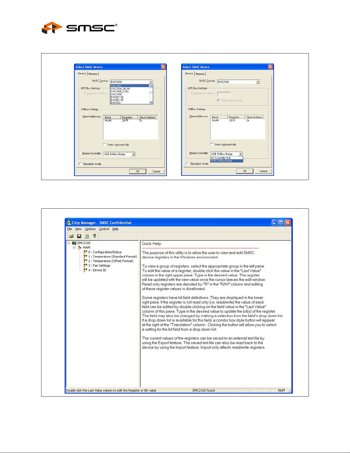
Figure 5.3 Selecting the Device and Master Controller Type
Fan Speed Control with the EMC2102 Device
Revision 0.2 (09-17-07)
Figure 5.4 ChipMan Operation Window
USER MANUAL SMSC EMC2102
10
Page 11

Fan Speed Control with the EMC2102 Device
Notes:
1. The EVB-EMC2102 needs to be configured using the USB SMBus Bridge to work properly. If in
the device selection window the Master Controller type is set to I/O Controller Hub then the
"Supported company ID on device not found" message will pop-up again.
2. Disconnecting the USB cable and reconnecting it without restarting the ChipMan may cause
register reading errors (all zeros). This problem can be cleared by re-selecting the EMC2102 device
through the device selection window (Options -> Select De vice).
3. The SMBus Slave Address could vary depending on the device. If a correct XML file is installed,
the ChipMan should be able to select the correct slave address automati cally. Refer to the device
datasheet for more details about the SMBus protocol and its configurations.
4. The SMSC ChipMan application allows viewing and changing register values for a variety of
devices. The ChipMan software only needs to be installed once to support all of these devices.
The list of supported devices may be found in the pulldown menu under Options -> Sel ect Device.
The next step will be to load the CMF file. Simply select File at the to p of the window, and "Import"
from the pull-down menu. A pop-up window will let the user to locate the right CMF.
Select the appropriate file and click "open". The CMF file will then load up the values into the EMC2102
device.
SMSC provides all CMF files for the operation experiments introduced in this user manual to help
customers to evaluate the EMC2102 device. Customers can also export their own configurations to
CMF files through the pull-down menu File -> Export/Export As.
The CMF file used for the Experiment 1 is EMC2102_manual.cmf.
To ensure the ChipMan application and the EMC2102 are communicating, select File -> Import and
then select the file emc2102_manual.cmf. This will import a configuration file to disable EMC2102’s
RPM control function and then set a valid fan control outp ut value. The on-board DC fan’s speed will
be reduced to about 5000 rpm at this time.
Select "3: Fan Settings" in the ChipMan window by double-clicking. The window as shown in
Figure 5.5, "Changing Fan Speed" will open. Double-click the "last value" of Fan Driver Setting register
(51h) and enter a new drive value (should be greater than 9Ah for the on-board DC fan). The fan
should respond, and the TACH Reading register (58h) should indicate an RPM reading.
It is recommended to set Autorefresh Registers option in ChipMan for all experiments in this user
manual. Select Options -> Autorefresh registers.
SMSC EMC2102
USER MANUAL Revision 0.2 (09-17-07)
11
Page 12
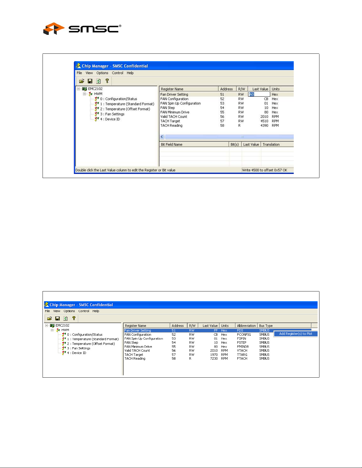
Figure 5.5 Changing Fan Speed
Fan Speed Control with the EMC2102 Device
5.1.3 Plotting From ChipMan
The ChipMan software has the ability to plot register values in real-time, u p to 10Hz continuous rate.
To select a register to plot, highlight its name or value, and right-click. A menu with a single entry "Add
register to Plot" will appear (Figure 5.6, "Plotting from the ChipMan"). Click the entry then a plot window
should appear, with a legend on top. When additional registers with the same data type are selected,
they are added to the existing plot window. In the experiment shown in Figure 5.7, "Plot Windows",
Drive Setting, TACH Target, and TACH Reading were selected. Note both the Tach register s are being
plotted on the same graph.
The last step is to start the plots. All plots can be started simultaneously by selecting the "Control"
pulldown from the main application window and then "Plot -> start all plots". Individual plots may be
paused at any time without loss of captured data on the other plot windows.
Revision 0.2 (09-17-07)
Figure 5.6 Plotting from the ChipMan
USER MANUAL SMSC EMC2102
12
Page 13

Fan Speed Control with the EMC2102 Device
The two plots shown in Figure 5.8, "Plot Examples" are in sync. If the scaled data is desired for
analysis or archival, the data may be stored in a semi-colon separated text file from each of the plot
windows. Simply select File Export, and enter a filename in the Save wind ow.
Figure 5.7 Plot Windows
TACH Target (57h)
Fan Driver Setting (51h)
TACH Reading (58h)
Figure 5.8 Plot Examples
5.2 Experiment 2 - RPM Based Closed-Loop Fan Control
The experiment 2 is designed to gain familiarity with the close d-loop RPM controller implemented in
the EMC2102. This experiment will discuss the effects of gain, spin-up, and minimum settings on the
closed-loop performance.
The cmf file for this experiment is EMC2102_RPM.cmf.
5.2.1 Getting Started
For all these tests, the Fan Drive Setting register (51h), the TACH Target register (57h) and the TACH
Reading registers (58h) are selected to plot. As bits are switched in each of the tests, the register name
and address will be provided.
SMSC EMC2102
USER MANUAL Revision 0.2 (09-17-07)
13
Page 14

5.2.2 Basic RPM Based Fan Control
The EMC2102 defaults will enable closed-loop operation. Prior to other options, exa mine the various
parameters on ChipMan window page 3: Fan Settings. The registers of most interest are the FAN
Minimum Drive (55h), and Valid Tach Count (56h). The closed-loop controller will not drive below the
minimum drive value, and will not respond to a TACH Target RPM speed less than the speed defined
by the Valid Tach Count register.
Note: The TACH reading is a reciprocal function of the fan speed, i.e. a higher TACH reading value
means a slower fan rpm speed. Refer to 6 "Appendix" for more details.
Same as Experiment 1, select Fan Drive Setting (51h), TACH Target (57h), and TACH Reading (58h)
for plotting. Start the plot windows in order to see the response, and command a series of Tach
Targets, starting at 4500 RPM, and going up in 500 RPM steps. The plots in Figure 5.9, "Plots for
Proper Control Settings" will be representative of the response generated.
Fan Speed Control with the EMC2102 Device
TACH Target (57h)
Fan Driver Setting (51h)
Figure 5.9 Plots for Proper Control Settings
Using this basic setup, it is possible to explore how well the fan is controlled using default values.
5.2.3 Effects of Loading
The EMC2102 has the ability to overcome changes in fan current requirements for a given RPM setting
due to aging, a blocked vent, dust, etc. This is because the controller does not rely on absolute drive
settings, but rather on driving the PID loop error to "0" (i.e., driving the TACH reading to equal to the
TACH target). To illustrate this feature, simply command an RPM setting (6000 RPM for this
experiment), and then use a piece of paper to cover the window of the fan. This will reduce the air
flow through the fan and decrease the wind resistance. With the same Fan Drive Setting value (~ 240d
in register 51h, set by devices’ RPM controller), less wind resistance will make the fan runn ing faster.
Once the PID controller inside the EMC2102 detects the difference between the TACH reading and
the TACH target (6000 RPM), it will adjust the output values (down to ~210d in this experiment) to
bring the fan speed back to the target, as shown in Figure 5.10, "Effects of Loading".
TACH Reading (58h)
Revision 0.2 (09-17-07)
USER MANUAL SMSC EMC2102
14
Page 15

Fan Speed Control with the EMC2102 Device
Figure 5.10 Effects of Loading
5.2.4 Register Change Summary
Fan was covered
The cover was removed
Table 5.1, "Register Change Summary for Experiment 2" lists all register value changes from the
default cmf load to accomplish the tests.
REGISTER
NAME ADDRESS
Fan
Configuration
Table 5.1 Register Change Summary for Experiment 2
DEFAULT
VALUE
52h 4Bh
(0100 1011b)
NEW
VALUE COMMENT
CBh
(1100 1011b)
Enables the RPM based closed-loop fan
control Algorithm
SMSC EMC2102
USER MANUAL Revision 0.2 (09-17-07)
15
Page 16

Fan Speed Control with the EMC2102 Device
5.3 Experiment 3 - Spin-up Configuration Options
This experiment is designed to gain familiarity with the various spin-up options available in the
EMC2102 devices.
This experiment will discuss the effects of Spin-Up Time and Spin-Up Levels. These parameters are
important to ensure a valid start, while minimizing the turn-on overshoot for initial low RPM settings.
(More examples regarding these two parameters can be found in Section 5.7.1, "Repetitious Spin-up
Routine Caused by Incorrect Settings").
The CMF file for this experiment is the same as for Experiment 1 , EMC2102_default.cmf.
5.3.1 Fan Control Parameters
The spin-up routine is a special algorith m that the EMC2102 uses to boot up the fan. In manual control
(open loop) mode, it is only invoked when starting from a ‘0’ value in the FAN Drive Setting register
51h.
In the RPM control (closed-loop) mode, the spin-up routine is invoked when the device is driving a
stalled fan to a valid target speed, i.e., the raw data value in register 57h (TACH Target) is smaller
than the one in register 56h (Valid TACH Count). During the normal operation while the fan is running,
the spin-up routine could also be invoked if the fan speed fell to below the valid fan sp eed, i.e, the raw
data value in register 58h (TACH Reading) is greater than the one in register 56h (Valid TACH Count),
since the fan will be considered as stalled by the controller.
There are several parameters that control the fan’s behavior during and a fter the spin-up routine, as
shown in Figure 5.11, "Fan Control Parameters".
When the spin-up routine is operating, the fan driver is set to full scale for one quarter of th e total user
defined spin up time. For the remaining spin up time, the fan driver output is set a user defined level
(60% or 75% of full drive). After the spin-up routine has finished, the RPM algori thm controls the fan
speed to the TACH targets. At this point if the EMC2102 cannot detect a valid fan speed (the
hexadecimal value in the TACH Reading register is higher than the Valid TACH Count re gister setting,
which means the fan speed is below the valid speed), i t will try to restart the fan.
Fan Drive Setting
(51h)
Use Normal
Closed-loop Algorithm
Fan Step
(54h[5:0])
Algorithm controlled drive
Prev Drive
Use Spin-Up Algorithm
100%
Spin Up Level =
60% ~ 75%
(53h[2])
New Target Count
¼ of Spin Up Time
The spin-up LEVEL (60% or 75%, defined by 53h[2]) has corresponding Fan Driver Setting
hexadecimal values (register 51h) which cab be calculated using FFh as 100% and 00h as 0%. For
Revision 0.2 (09-17-07)
TACH Target
Changed
Spin Up Time
(53h[1:0])
Update Time
Check TACH
(52h[2:0])
Target Count
Reached
Figure 5.11 Fan Control Parameters
USER MANUAL SMSC EMC2102
16
Page 17

Fan Speed Control with the EMC2102 Device
the 60% drive the register 51h value is 153d o r 99h, and for 75% it is 191d or BFh. Those two drive
settings will run a DC fan at two different speeds and we will call them rpm60 an d rpm75. Depending
on the fan, the speed for the same drive setting will vary.
All data and plot examples in this document were taken using an EVB-EMC2102 board with the onboard DC fan. This fan has an rpm60 of 4500 rpm, and an rpm75 of 5650 rpm.
5.3.2 Getting Started
For all these tests, the Fan Drive Setting register (51h), the TACH Target register (57h) and the TACH
Reading registers (58h) are selected to plot. As bits are switched in each of the tests, the register name
and address will be provided.
5.3.3 Forced Kick Function
The EMC2102 has a forced 100% kick at turn-on. This feature drives the fan at maximum voltage for
¼ of the time set by the SPINUP_TIME[1:0] bits in register 53h. The plots in Figure 5.12, "Forced Kick
Function" illustrate this function with a spin-up time of 2 .0 sec while the TACH Target register (57h) is
changed from 0 rpm to 5200 rpm.
Selecting a different "Time per Division" value in the pull-down menu in the center bottom of the plotting
window, to make the 100% kick pulse can be viewed. This scale change affects both playback, and
real-time mode. The rate at which data is recorded is unaffected by changing this parameter.
100% Kick Pulse for 500 ms
75% Spin-Up
Spin-Up
Time = 2 s
5.3.4 Spin-Up Level
Depending on the application, the value of LEVEL (spin-up level, bit[1] in register 53h) may need to
be adjusted to achieve the best fan control result. The plots in Figure 5.13, "60% Spin Level Setting"
show the same experiment as Section 5.3.3, "Forced Kick Function" with a 60% spin-up level. Note
the a smaller overshoot at the lower LEVEL setting.
(1/4 of Spin-Up Time)
Level
Normal Fan Drive
(for 5200 rpm)
Figure 5.12 Forced Kick Function
SMSC EMC2102
USER MANUAL Revision 0.2 (09-17-07)
17
Page 18

Figure 5.13 60% Spin Level Setting
Note: When a fan starts, the first TACH count captured by the EMC2102 may not reflect the fan’s
speed correctly, since the counting clock (32.768 kHz) could only partially fill the counting
window, which will cause a higher speed reading. Also for some fans, the tachometer may not
work immediately after the fan starts therefore some invalid TACH signals (very short, noisy
pulses) could be sent out at the beginning. In eithe r case, the invalid TACH counts could be
displayed on the ChipMan plots (Figure 5.13), but will never be used to control the fan because
the EMC2102 will not look at the TACH reading until the end of spin-up routine.
Fan Speed Control with the EMC2102 Device
Invalid TACH Count
5.3.5 Spin-Up Time
The EMC2102 FAN Spin Up Configuration register (53h) contains 2 bits to set the overall spin-up time.
This parameter allows for tailoring of rapid and slow response fans. Repeat the experiment in
Section 5.3.3 with 500 ms SPINUP_TIME. This will provide a quicker response with smaller overshoot,
as shown in Figure 5.14, "Reduced Spin-up Time".
In general, spin-up time should be tailored for the fan type being used or the effect may be undesirable.
Revision 0.2 (09-17-07)
Figure 5.14 Reduced Spin-up Time
USER MANUAL SMSC EMC2102
18
Page 19

Fan Speed Control with the EMC2102 Device
5.3.6 Register Change Summary
Table 5.2, "Register Change Summary for Experiment 3" lists all register value changes from the
default cmf load to accomplish the tests.
Table 5.2 Register Change Summary for Experiment 3
REGISTER
NAME ADDRESS
FAN Spin Up
Configuration
DEFAULT
VALUE
53h 01h
(00000001b)
NEW
VALUE COMMENT
03h SPINUP_TIME of 2.0 sec
05h Change the LEVEL from 60% to 75%
SMSC EMC2102
USER MANUAL Revision 0.2 (09-17-07)
19
Page 20

Fan Speed Control with the EMC2102 Device
5.4 Experiment 4 - RPM Drive Mode Rate Controls
This experiment is designed to gain familiarity with the rate control options avail able in the EMC2102
devices.
This experiment will discuss the effects of Maximum Fan Step and Update rate that can be used to
control the ramp rate of a fan. The two parameters ensure the fan reaches the desired drive in a
reasonable time with no oscillations.
The CMF file for this experiment is the same as for Experiment 1 , EMC1202_default.cmf.
5.4.1 General Setup
For all these tests, the Fan Drive Setting register (51h) and the TACH Reading registers (58h) are
selected to plot. As bits are switched in each of the tests, the register name and address will be
provided.
5.4.2 Controlling the Ramp Rate
Controlling the ramp rate can improve the performanc e of the fan control loop by limiting the slew rate
of the fan drive. The EMC2102 uses the UPDATE bits in the FAN Configuration register (52h, bits [2:0])
to determine the time interval between two updates of the controller output, and uses the FAN Step
register (54h) to determine the maximum allowed hexadecimal co unt (STEP) of the output (Refer to
Figure 5.11 "Fan Co ntrol Parameters" for more details). These two parameters can only work in the
RPM control mode. When the RPM control function is disabled (52h[7]= 0), any change in the Fan
Drive Setting register (51h) will immediately change the output.
The plots in Figure 5.15, "Default Ramp Rate" illustrate the drive and response with the default
UPDATE (400ms) and default STEP SIZE (Max. 16 drive settings per update), while changing the fan
target speed from 4000 rpm to 6000rpm.
Figure 5.15 Default Ramp Rate
The ramping rate in this mode can be accelerated or slowed down , depending on application and the
values of register 52h (UPDATE) and 54h (STEP SIZE). In the next experiment (Figure 5.16, "Default
Step Size with Different UPDATE Settings"), the default STEP SIZ E with different UPDATE (400 ms
and 100 ms) were used, The 100 ms setting has the effect of speeding the loop up by a factor of 4,
as that is the ratio between minimum (100ms) and default (400ms) UPDATE settings.
Revision 0.2 (09-17-07)
USER MANUAL SMSC EMC2102
20
Page 21

Fan Speed Control with the EMC2102 Device
Figure 5.16 Default Step Size with Different UPDATE Settings
In the next experiment (Figure 5.17, "Default UPDATE with Different Step Size Settings"), two different
maximum step sizes, 16 and 63, were used. with the 63 STEP SIZE setting, the output takes less
steps (updates) from 4000 rpm to 7500 rpm because it gives the fan more power to follow the desi red
rpm settings.
UPDATE
= 100 ms
UPDATE
= 400 ms
STEp SIZE
= 63
STEp SIZE
= 16
Figure 5.17 Default UPDATE with Different Step Size Settings
In the last experiment, an extremely slow ramp rate is demonstrated. The UPDATE was set to
maximum (1600 ms), and the STEP SIZE was changed to 01h (Figure 5.18, "Exceptionally Slow
Rate"). Note the large scale of the “Time per division” in the figure.
SMSC EMC2102
USER MANUAL Revision 0.2 (09-17-07)
21
Page 22

Figure 5.18 Exceptionally Slow Rate
5.4.3 Register Change Summary
Fan Speed Control with the EMC2102 Device
Table 5.3, "Register Change Summary for Experiment 4" lists all register value changes from the
default cmf load to accomplish the tests.
Table 5.3 Register Change Summary for Experiment 4
REGISTER
NAME ADDRESS
FAN Step 54h 10h 01h Demonstrate RRC long duration
Fan
Configuration
52h CBh C8h, CFh Demonstrate min (C8h) and max (CFh) UPDA TE rates
DEFAULT
VALUE
NEW
VALUE COMMENT
applied to RRC
Revision 0.2 (09-17-07)
USER MANUAL SMSC EMC2102
22
Page 23

Fan Speed Control with the EMC2102 Device
5.5 Experiment 5 - Optimizing RPM Control Response
This experiment is designed to gain familiarity with the parameters that affect the closed-l oop control ler
implemented in the EMC2102. All these registers are located on the Fan Setting page in ChipMan.
This experiment will go through each register, examining the effects of parametric changes on the
closed-loop controller in RPM mode.
5.5.1 General Setup
For all these tests, the Fan Drive Setting register (51h), the TACH Target register (57h) and the TACH
Reading registers (58h) are selected to plot. As bits are switched in each of the tests, the register name
and address will be provided.
5.5.2 Fan Configuration Register (52h)
The Fan Configuration Register stores the basic operation parameters of the closed-loop controller.
The EN bit turns on the RPM controller, and locks out manual updates to the Fan Drive Setting register
(51h).
The next two parameters, LIMIT2K and EDGES[1:0] (both in register 52h) describe the fan itself. The
EDGES[1:0] tell the controller how many tach edges to examine to determine the fan speed. The
LIMIT2K parameter tells the RPM controller how to interpret the TACH Target register (57h). The value
of this parameter provides an operating range for the fan by specifying the minimum rpm: the 500 rpm
setting is for low speed fans and the 2000 rpm setting is typical for notebook and desktop fans (high
speed fans). (Please refer to Section 6.1, "DC Fan Basics - Poles, Tach Meter Pulses and Edges" for
more details about the TACH edges and ranges.)
For all experiments in this suite, the default values have been used. This keeps the scaling of those
values fixed, allowing the ChipMan application to appropri ately scale the counts to RPM values.
The UPDATE[2:0] parameter controls the speed at which the RPM controller updates the output drive,
as already been discussed in Section 5.4, "Experiment 4 - RPM Drive Mode Rate Controls". This
parameter is independent of the TACH Reading updates, which are controlled by the EDGES[1:0]
parameter. The plots in Figure 5.19, "Update Time Modifications" show the effect of UPDATE on the
closed-loop performance when starting the on-board fan. The numbers (in unit of second) in the left
plot indicate the UPDATE value used for that sequence. By experimenting with the different update
times you can determine the most stable setting for the fan to be controlled.
0.1s 0.2s 0.4s 0.8s 1.6s
Invalid TACH signals
(Ignored by Controller)
SMSC EMC2102
Figure 5.19 Update Time Modifications
USER MANUAL Revision 0.2 (09-17-07)
23
Page 24

Fan Speed Control with the EMC2102 Device
5.5.3 FAN Minimum Drive Register (55h) and Valid TACH Count (56h)
These two registers assist the user in defining the operational environment for a given fan. The
Minimum Drive register is an absolute minimum value the RPM controller may drive to in an attempt
to achieve low RPM settings. The Valid Tach Count register is used to compare against the Tach Target
register. No value less than the Valid Tach Count will be accepted by the controller. To examine this
feature, set the minimum drive to C0h, and command an RPM setting of less than 5500 RPM. The fan
will start at about 5600 rpm (51h = C0h). Set the target to 6000 rpm, and the fan speed follow s. Drop
the fan target speed from 6000 rpm to 4500 rpm, the real fan speed will only drop to about 5560 rpm,
as shown in Figure 5.20, "Minimum Drive Setting".
Fan starts at
Minimum Drive
Fan will not run below
Minimum Drtive
Figure 5.20 Minimum Drive Setting
Likewise, the Valid TACH Count register operation is simple to show. Start the fan at 6000 RPM with
all default setting, and then set the Valid TACH register to 5000 RPM. Enter a comman d of 4800 RPM,
and the fan will not respond as shown in Figure 5.21, "Valid Tach Count Setting".
Target of 4800 rpm
Figure 5.21 Valid Tach Count Setting
Revision 0.2 (09-17-07)
USER MANUAL SMSC EMC2102
24
Page 25

Fan Speed Control with the EMC2102 Device
5.5.4 Register Change Summary
Table 5.4, "Register Change Summary for Experiment 7" lists all register value changes from the
default cmf load to accomplish the tests.
Table 5.4 Register Change Summary for Experiment 7
REGISTER
NAME ADDRESS
Fan
Configuration
Valid Tach
Count
DEFAULT
VALUE
52Bh CBh 4Bh Disable RPM based fan control algorithm
ABh C8h - CFh Demonstrate UPDATE effect
56H 2010d 5000d C hanged from 2010 RPM to 5000 RPM to show
NEW
VALUE COMMENT
the effect in closed-loop
SMSC EMC2102
USER MANUAL Revision 0.2 (09-17-07)
25
Page 26

5.6 Experiment 6 - Limits and Alerts
This experiment is designed to gain familiarity with the control registers for generating fan related
alarms and alerts associated with the EMC2102.
The CMF file for this experiment is EMC2102_default.cmf.
5.6.1 General Setup
For all these tests, the Fan Drive Setting register (51h), the TACH Target register (57h) and the TACH
Reading registers (58h) are selected to plot. As bits are switched in each of the tests, the register name
and address will be provided.
5.6.2 Fan Spin and Stall Interrupts
The Configuration/Status page in the ChipMan application contains all the Interrupt configuration and
status registers for the fan. In this experiment, the Fan Stall and Fan Spin status bits will be checked.
In order to see the status bits change, the Interru pt Status 2 register (23h) is plotted along with other
registers listed above. The Interrupt Mask register (24h) should be set to 10h (default) for this set of
experiments.
Start the plotting function within ChipMan, and force the fan to stop spinning. This will induce a Fan
Stall condition. The plot of the Status Register will show a peak of 1 count for the stall condition,
followed by peaks of 2 counts for each time the spin-up routine is invoked, as shown in Figure 5.22,
"Fan Spin and Stall". In order to see the spikes mentioned above, the max scale on the register 27h
plot needs to be modified. To do this, simply double click the 255 at the top of the "Y" axis, type a
different maximum value (10) and enter. And then double click the 0 at the bottom of the "Y" axis, type
a minimum value and enter. The scale will be changed.
Fan Speed Control with the EMC2102 Device
Revision 0.2 (09-17-07)
USER MANUAL SMSC EMC2102
26
Page 27

Fan Speed Control with the EMC2102 Device
Fan Drive Setting
(51h)
TACH Target (57h)
TACH Reading (58h)
Stall
Interrupt Status 2
(23h)
Figure 5.22 Fan Spin and Stall
5.6.3 Register Change Summary
All register values are default for the tests in this section.
SMSC EMC2102
USER MANUAL Revision 0.2 (09-17-07)
27
Page 28

Fan Speed Control with the EMC2102 Device
5.7 Experiment 7 - Troubleshooting
5.7.1 Repetitious Spin-up Routine Caused by Incorrect Settings
At the end of spin-up routine (see Section 5.3.1, "F an Control Parameters"), the EMC2102 checks the
TACH Reading register (58h). If the value in this register is greater th an the Valid TACH Count (56h),
which means the fan is running at a speed slower than the minimum valid speed, the spin-up routine
will be restarted (Figure 5.23, "Fan Spin-up Routine Restarted Repeatedly").
Figure 5.23 Fan Spin-up Routine Restarted Repeatedly
Depending on the fan characters and EMC2102 settings, there are several situations at the end of
spin-up routine which will be discussed.
Notes: F or ease of understanding, all TACH values will be converted to RPM values in the following
examples.
5.7.1.1 Case 1 - Spin-up Lvel RPM < Valid RPM < Target RPM
In this case, the spin-up level rpm (rpm60 or rpm75) is smaller than both valid rpm (function of 56h)
and target rpm (function of 57h). The theoretical plot of this situation is shown in Figure 5.24,
"Theoretical Plot of Case 1".
Since the fan speed at the end of spin-up routine is always below the minimum valid speed (a function
of 56h), the EMC2102 will think the fan is not running, and will try to restart the fan with spin-up routine
over and over.
Using the EVB-EMC2102 to test this situation with rpm60 (~4500 rpm), simply set the Valid TACH
register (56h) with 4800 rpm and start the fan with TACH Target (57h) = 5000 rpm. The repeating spinup routines can be observed (Figure 5.25, "Spin-up Case 1 Fix 1").
For rpm75 (~5650 rpm), set 56h = 6000 rpm and 57h = 6500 rp m, as shown in Figure 5.26, "Spin-up
Case 1 Fix 2".
There are mainly two ways to fix this problem. If the spin-up LEVEL in 53h is 60%, the n change it to
75%, as shown in Figure 5.25.
Revision 0.2 (09-17-07)
USER MANUAL SMSC EMC2102
28
Page 29

Fan Speed Control with the EMC2102 Device
Fan Speed
(RPM)
RPM for
100% Drive
Target Speed
Valid Speed
rpm60 or rpm75
Fan Speed
¼ of Spin Up Time
Spin Up Time
Check TACH
Figure 5.24 Theoretical Plot of Case 1
SMSC EMC2102
Spin Up Level
Changed to 75%
Figure 5.25 Spin-up Case 1 Fix 1
If the fan is already set to 75% level, we will need to lower the valid speed (function of 56h, Valid
TACH) to a value below the rpm75, to fix the problem.
To test this situation, set spin-up level to 75% (53h [2] = 1), set the Valid TACH Count (56h) = 6000
rpm and then start the fan (57h) with 6500 rpm. The spin-up routine will run rep eatedly.
Change the Valid TACH Count (56h) to 5800 rp m, the problem cannot be fixed since the valid speed
is still higher than the fan speed (rpm75 = 5650 rpm).
Set 56h = 5580 rpm which is below 5650 rpm (the rpm75), the system gets out of the spin-up routine
(Figure 5.26).
USER MANUAL Revision 0.2 (09-17-07)
29
Page 30

Valid Speed = 6000 rpm
Fan Drive Setting (51h)
Valid Speed = 5800 rpm
Valid Speed = 5580 rpm
Fan Speed Control with the EMC2102 Device
Figure 5.26 Spin-up Case 1 Fix 2
5.7.1.2 Case 2 - Valid RPM << Target RPM < Spin-up Level RPM
In this case, the target speed is smaller than the spin-up level speed (rpm60 or rpm75) and is much
bigger than the valid speed. The theoretical plot of this si tuation is shown in Figure 5.27, "Theoretical
Plot of Case 2".
Since the fan speed at the end of spin-up routine is always higher than the minimum valid speed, the
EMC2102 will go to the normal operation after the spin-up routi ne.
Using the EVB-EMC2102 to test this situation with rpm75 (~5650 rpm), simply set the Valid TACH
register (56h) with 4500 rpm and start the fan with TACH Target (57h) = 5 500 rpm (Figure 5.28, "Spin-
up Case 2").
Fan Speed
(RPM)
RPM for
100% Drive
rpm60 or rpm75
Fan Speed
Target Speed
Valid Speed
¼ of Spin Up Time
Revision 0.2 (09-17-07)
Spin Up Time
Check TACH
Figure 5.27 Theoretical Plot of Case 2
USER MANUAL SMSC EMC2102
30
Page 31

Fan Speed Control with the EMC2102 Device
Fan Drive Setting (51h)
Figure 5.28 Spin-up Case 2
5.7.1.3 Case 3 - Valid RPM =< Target RPM << Spin-up Level RPM
In this case, the target speed is only a little greater than the valid speed, and both of them a re much
smaller than the spin-up level speed (rpm60 or rpm75). The theoretical plot of this situation is sho wn
in Figure 5.29, "Theoretical Plot of Case 3".
Fan Speed
(RPM)
RPM for
100% Drive
rpm60 or rpm75
Fan Speed
Target Speed
Valid Speed
¼ of Spin Up Time
Spin Up Time
Check TACH
Figure 5.29 Theoretical Plot of Case 3
SMSC EMC2102
Since the fan speed at the end of spin-up routine is higher than the minimum valid speed, the
EMC2102 should go to the normal operation after the spin-up routine. However, because the large
speed difference between the spin-up level speed (rpm60 or rpm75) and the target speed, the clo sedloop controller will try to make a big adjustment o f its output to reach the target speed. With incorrect
settings (such as big output step or short update time), this adjustment could easily cause an
undershoot and make the fan speed below the valid rpm, a nd than make the spin-up routine restart.
USER MANUAL Revision 0.2 (09-17-07)
31
Page 32

Fan Speed Control with the EMC2102 Device
Using the EVB-EMC2102 to test this situation with rpm75 (~5650 rpm), simply set the Valid TACH
register (56h) with 4500 rpm, set the UPDATE (52h[2:0]) = 100ms and start the fan with 4700 rpm, the
spin-up routine starts over ‘and over (Figure 5.30, "Spin-up Case 3").
To fix this prob lem, change the UPDATE (52h[2:0]) back to 400 ms. It will give the fan more time to
reach the speed of the previous step and reduce the overshoot/undershoot. Another solution is to
decrease the Fan Step settings which will force the controller to take smaller steps to achieve the target
speed.
When the target speed is too close to the valid speed, the problem will not only occur when the fan
starts. It may also cause problems in the normal operation after the spin-up, since the fan speed
reading errors (caused by fan load changes, tachometer truncation errors, circuit noises, etc.) could
drop it below the valid speed and cause a spin-up routine restart. (Figure 5.31, "Spin-up Routine
Restarted During Normal Operation").
UPDATE = 400 ms
UPDATE = 100 ms
Undershoots cause
the fun runs below
valid speed
Figure 5.30 Spin-up Case 3
Revision 0.2 (09-17-07)
Figure 5.31 Spin-up Routine Restarted During Normal Operation
USER MANUAL SMSC EMC2102
32
Page 33

Fan Speed Control with the EMC2102 Device
5.7.1.4 Case 4 - 4.Valid RPM < Spin-up Level RPM (rpm60 or rpm75) < Target RPM
In this case, the spin-up level speed (rpm60 or rpm75) is greater than the valid speed and smaller than
the target speed, as shown in Figure 5.32, "Theoretical Plot of Case 4".
At the end of spin-up routine, the closed-loop control will drive the fan up to reach the target, therefore
the fan speed will never be lower than the valid speed. The EMC 2102 will go to the normal operation
after the spin-up routine.
Using the EVB-EMC2102 to test this situation with rpm60 (~4500 rpm), simply set the Valid TACH
register (56h) with 3500 rpm and start the fan with TACH Target (57h) = 5 000 rpm (Figure 5.33, "Spin-
up Case 4").
Fan Speed
(RPM)
RPM for
100% Drive
Target Speed
rpm60 or rpm75
Fan Speed
Valid Speed
¼ of Spin Up Time
Spin Up Time
Check TACH
Figure 5.32 Theoretical Plot of Case 4
SMSC EMC2102
Figure 5.33 Spin-up Case 4
USER MANUAL Revision 0.2 (09-17-07)
33
Page 34

Fan Speed Control with the EMC2102 Device
5.7.1.5 Case 5 - Correct RPM Relationships with a Slow Response DC Fan
In this case, the spin-up routine is too short to make the fan reach a speed h ighe r than the vali d speed.
Since the EMC2102 cannot detect a valid TACH at the end of spin-up routine, it will try to restart the
fan. Depending on the fan, it is possible that after several spin-up cycles, the fan can rea ch the valid
speed and operate normally.
Using the EVB-EMC2102 to test this situation with rpm60 (~4500 rpm), simply set the SPINUP_TIME
(53h[1:0]) = 250 ms, Valid TACH (56h) = 4400 rpm, and start the fan wi th TACH Target (57h) = 5500
rpm. Multiple spin-up routines will be observed (Figure 5.34, "Spin-up Case 5").
Figure 5.34 Spin-up Case 5
To fix this problem, stop the fan an d set the SPINUP_TIME = 2s, and restart the fan with 5500 rpm.
Increasing Spin-up time will make a longer 100% "kick" time and provide the fa n with more power to
speed-up (Figure 5.35, "Spin-up Case 5 Fix").
The problem also can be fixed by changing the spin up level from 60% to 75% if not do ne already, as
previously discussed.
Longer 100% kick provides more
driving power to speed-up the fan
Revision 0.2 (09-17-07)
Figure 5.35 Spin-up Case 5 Fix
USER MANUAL SMSC EMC2102
34
Page 35

Fan Speed Control with the EMC2102 Device
n
6 Appendix
6.1 DC Fan Basics - Poles, Tach Meter Pulses and Edges
An n-pole fan has n pairs of North-South magnetic poles which are generated by electromagnet coils.
At anytime, only one pair of coils are driven and which coil pair gets driven is determined by a
component called Hall Sensor. The architecture of a typical 2-pole DC fan is shown in Figure 6.1, "A
Typical 2-pole DC Fan".
Prote ctio
Diode
Hall
+
Sensor
S -
N +
-
1
S -
+
-
N +
VDD
TACH
Ha ll
Sensor
Mot or
Wind i n g
Driver
Mot or
Winding
Mot or
Winding
1
2
GND
Figure 6.1 A Typical 2-pole DC Fan
The output of the hall sensor is also the TACH (or Tachometer) signal. When the magnetic field around
the Hall Sensor changes its direction, the sensor ’s output level will follow the change to create a square
wave signal as shown in Figure 6.2, "Output Signal of a 2-pole Fan".
Assuming 2-pole fan is running at a speed of 6000 RPM, it will rotate 100 revolutions per second. With
2 pulses per revolution, the TACH pulse signal frequency will be 200Hz (Figure 6.2). Since a higher
RPM will yield a higher TACH frequency, or a shorter period between pulses, th e TACH signal can be
used by the EMC devices to determine the speed of the fan. Generally speaking, we h ave:
TACH Pulse Frequency (in HZ) = (RPM / 60) x (# of Pole)
1 complete fan revolution
= 2 pulses (5 edges)
Fan Tach Signal
Figure 6.2 Output Signal of a 2-pole Fan
EMC2102 uses a clock (32.768KHz for example) to fill in a window between a programmable n umber
of Tachometer edges. A counter starts on a specific rising edge and keeps counting until it sees the
‘set’ number of edges, and then saves the counted pulse numbers into register 58h, the TACH Reading
register.
SMSC EMC2102
USER MANUAL Revision 0.2 (09-17-07)
35
Page 36

T
P
Fan Speed Control with the EMC2102 Device
Note: Although users can set the number of edges (in register 52h) to eith er 3, 5, 7 o r 9, it is stron gly
recommended using the default value 5 while driving a 2-pole DC fan. This equal to one
complete fan revolution for a 2-pole fan.
5 EDGES
3 EDGES
Fan Tach Signal
32.768kHz
Clock
n-EDGE WINDOW
7 EDGES
T
WINDOW
Figure 6.3 Fan TACH Measur ement With EMC2102
ChipMan translates TACH counts to the RPM value and displays the fan speed. For applications not
using ChipMan software, the following equation can be used to convert the TACH Reading values to
the real RPM speeds.
where:
RPM *
EDGES
=
oles
1−
983040
*
COUN
m
EDGES = number of edges set by register 52h[4:3]
COUNT = TACH Reading (58h) value [1]
Poles = number of pole pairs in the DC fan
m = factor defined by LIMIT2K (52h[6])
(m = 1 for 500 rpm and m = 4 for 2000 rpm)
6.2 Characterizing a DC Fan with EVB-EMC2102 and ChipMan
As a very important component in the closed-loop, the DC fan’s characteristics have a great impact
on the control system’s performance. Using the EVB-EMC2102 and ChipMan software tool, a 5V DC
fan’s characteristics can be easily tested.
In general, the following parameters need to be characterized:
Minimum Startup Spee d
Stall Spee d
Minimum Valid TACH Speed
Maximum Fan Speed
Spin-up Level (i.e., rpm60 and rpm75. Refer to Section 5.3.1, "Fan Control Parameters" for more
details)
6.2.1 General Setup
Setup the system and make sure the hardware and software are working as discussed in Section
5.1, "Experiment 1 - Manual Fan Control".
Unplug the on-board DC fan from connector P1
Connect the DC fan to be tested to P1 (refer to EVB-EMC2102 User Manual for the DC fan
connector pinouts)
Revision 0.2 (09-17-07)
USER MANUAL SMSC EMC2102
36
Page 37

Fan Speed Control with the EMC2102 Device
Verify the device is in Manual Mode (52h[7] = 0)
6.2.2 Set the Correct LIMIT2K Value
Register 52h (FAN Configuration) bit 6 (LIMIT2K) is a fan dependent parameter as discussed in
Section 5.5.2, "Fan Configuration Register (52h)". When reading the TACH Reading register (58h),
ChipMan uses the default LIMIT2K value (2000 rpm) to convert it to an rpm sp eed
If the RANGE is set to 500 rpm, the TACH Reading value on the ChipMan display should be
multiplied by 0.5
6.2.3 Determine the Number of Poles and the Maximum Fan Speed
Set the device in Manual Mode (52h[7] = 0)
Start the fan with 100% output drive (register 51h = 255h)
EMC2102 assumes that it is driving a 2-pole fan by default. If the fan speed in registe r 58h does
not match the fan’s maximum speed specified in its datasheet, then it is not a 2-pole fan. The
EDGES value in register 52h has to be modified, or all speed read ings displ ayed b y Chip Man have
to be re-calculated using Equation 1
The value in 58h also can be compared to the fan’s tachometer output frequency obtained by an
oscilloscope to verify its correctness
Record the rpm values in the TACH Reading register (58h) as the maximum fan speed
The maximum fan speed for the EVB-EMC2102 on-board DC fan is abou t 7000 rpm
6.2.4 Determine the Minimum Startup Speed
Set the device in Manual Mode (52h[7] = 0)
Write a value (for example 80h) to Fan Driver Setting register (51h)
If the fan cannot start, then increase the drive value until the fan start
If the fan starts at the first drive value, then stop the fan (51h = 0) and write a smaller value to
register 51h
Repeat the above steps until the minimum startup speed is determined. Record the drive value in
51h and the fan speed in register 58h
The minimal start speed for the EVB-EMC2102 on-bo ard DC fan is about 4500 rpm with output
drive of 9Eh
6.2.5 Determine the Stall Speed
While the fan is running, reduce the fan drive value in register 51h, step by step, until the fan stops
Write down the drive value in 51h and the fan speed in register 58h before the fan stops
The stall speed for the EVB-EMC2102 on-board DC fan is about 3000 rpm (~70h)
6.2.6 Determine the Minimum Valid TACH Speed
While the fan is running in non-RPM mode, reduce the fan drive value in register 51h, step by step
Monitor the rpm values in the TACH Reading register (58h)
Using an oscilloscope to observe the fan’s Tachometer signal
When invalid, the TACH signal will become erratic with incorrect values (usually much less TACH
counts or very high rpm) in register 58h
The TACH signal may be valid until the fan stalls. If it happens, the fan’s stall speed could be used
as the minimum valid TACH speed
SMSC EMC2102
USER MANUAL Revision 0.2 (09-17-07)
37
Page 38

6.2.7 Determine the Spin-up Levels (rpm60 and rpm75)
Drive the fan with 60% of the maximum output (register 51h = 99h) and the rpm value in the TACH
Reading register (58h) will be the fan’s rpm60
Drive the fan with 75% of the maximum output (register 51h = BFh ) and the rp m value in th e TACH
Reading register (58h) will be the fan’s rpm75
6.2.8 Using the Tested Parameters
All parameters discussed above will vary from fan to fan and with fan aging, therefore some margins
have to be added when selecting the fan control settings. A minimum of 10% of full fan speed is
recommended for margins.
6.2.8.1 Spin-up LEVEL (Register 53h[2])
This parameter has to be set so that the corresponding fan speed is greater than Minimum Startup
Speed + Margin.
6.2.8.2 Minimum Fan Speed
To avoid stalling, the fan speed (a function of Fan Driver Setting [51h] or a function of TACH Target
[57h]) needs to be greater than Stall Speed + Margin at all times.
Fan Speed Control with the EMC2102 Device
6.2.8.3 Valid TACH Count Speed (Function of Register 56h)
The EMC2102 will not respond to any TACH Target (57h) value that has a corresponding speed sl ower
than Minimum Valid TACH Speed + Margin, unless the value is FFh which will stop the fan. This
ensures that the RPM control algorithm will not drive too low.
6.2.8.4 Maximum Fan Speed
Use the measured maximum fan speed minus margin as the Maximum Fan Speed.
Revision 0.2 (09-17-07)
USER MANUAL SMSC EMC2102
38
 Loading...