

Page 1

SM PRO AUDIO M-PATch 4m
M-patch 4m
STUDIO monitor controller with Talkback
Manual V1.0
Page 2

SAFETY INSTRUCTIONS
CAUTION: To reduce the risk of electrical shock, do not remove the
cover or rear panel of this unit. No user serviceable parts inside. Refer
servicing to qualified personnel only.
WARNING: To reduce the risk of fire or electrical shock, do not expose
this equipment to rain or moisture.
All safety and operation instructions of this manual should be read and adhered
to before operating this equipment.
Retain Instructions: Please retain all safety and operating instructions for future reference.
Follow Instructions: All operation and user instructions should be followed.
Water, Liquid, and Moisture: The equipment should not be used near water, rain, or other
liquids. Make sure that no liquid can leak, spill, or otherwise seep into the equipment.
Ventilation: Please place the equipment so that no obstacles interfere with or impede the
flow of air through the ventilation openings.
Heat:The equipment should be situated away from heat sources such as heaters,
radiators, ovens, and other appliances that produce heat.
Power Source:Make sure your equipment is set to the correct voltage for the country in
which it will be used.
Grounding and Polarization:Precautions should be taken so that the equipment’s
electrical grounding or polarization is not defeated.
SM PRO AUDIO M-Patch 4m
Power Cord Protection:Power supply cords should be routed so that they are not likely to
be walked on, pinched, damaged, worn, or rubbed by any other device or obstacle.
Cleaning:The equipment should be cleaned only with a light soft cloth. Do not use harsh or
corrosive products on the unit.
Periods of Inactivity:The power cord of the appliance should be unplugged from the outlet
when left unused for a long period of time.
Damage Requiring Service:The equipment should be serviced by qualified service
personnel when:
• The power supply cord or plug has been damaged; or
• Objects have fallen onto, or liquid spilled into the equipment; or
• The equipment has been exposed to rain; or
• The equipment does not appear to operate normally or exhibits a marked change in
performance; or
• The equipment has been dropped, or the enclosure damaged.
Servicing:
The user should not attempt to service the equipment beyond what is described in the
Operating Instructions.
All other servicing should be referred to qualified service personnel.
Page 3

SM PRO AUDIO M-PATch 4m
Foreward
Dear Customer,
Thank you very much for expressing your confidence in SM Pro Audio products
by purchasing this unit. The M-Patch 4M was designed to be a comprehensive
studio monitor controller for home, project and professional studios, sound
equipment rental companies, repair centers, schools and fixed installations—in
short, virtually any and all venues where audio products are used. Drawing on
years of hands-on experience in the audio industry and valuable suggestions
from our customers, our engineers have developed a product that we are
certain will more than meet your expectations. As with all SM Pro Audio
equipment, the M-Patch 4M was designed to provide you with superb
performance, excellent technical specifications, and uncompromising audio
quality at an extremely affordable price.
Regards,
SM Pro Audio
IMPORTA N T:
High output volumes may d a m a g e your ears,
your mon i tor s , a n d /or you r he a dph o n es. Turn dow n the
LEVE L con t rol s bef o re y ou s wit c h on the
INSTALLATION
Your SM Pro Audio M-Patch 4M was carefully packed at the factory and the
packaging was designed to protect the unit from rough handling. Nevertheless,
we recommend that you carefully examine the packaging and its contents for
any signs of physical damage that may have occurred in transit.
If the unit is damaged, please do not return it to us, but notify your dealer and
the shipping company immediately, otherwise claims for damage or replacement
may not be granted. Shipping claims must be made by the consignee.
PLACEMENT
The SM Pro Audio utilizes an electronic circuit. Be sure that there is
enough air space around the unit for cooling. To avoid overheating, please do not
place the unit on high temperature devices, such as power amplifiers, or near
other units, such as wireless devices, that may transmit high frequencies.
Mains voltage
The M-Patch 4M can be used with voltages ranging from 100V AC to 240V AC.
Please make sure that you have selected the correct voltage range on the back
of the unit, and that the required fuse setting is correct, before switching the unit
ON. Any damage occurring as a result of incorrect voltage selection may not be
covered under warranty.
M-Patch 4M
M-Patch 4M.
Page 4

M-Patch 4m OVERVIEW
The M-Patch 4M is a multichannel passive analog attenuator designed to provide
sonically transparent level control over a variety of stereo audio signals. It allows
you to connect multiple input signals, route them to various destinations, and
control their levels via a series of rotary volume attenuators. The Master Attenuator
utilizes discrete 0.5% resisters with a switched mechanism—a design that offers
superior accuracy over standard variable resistor designs, especially at critical low
volume levels.
Multiple switches provide for mute, source selection, output assignment, and
stereo/mono operation. A built-in talkback microphone, which automatically ducks
the Control Room outputs -20dB when engaged, an on-board headphone amplifier,
and configurable desktop or rackmount operation, make the M-Patch 4M an ideal
centerpiece for monitor control in home, professional, and project studio applications.
SM PRO AUDIO M-Patch 4m
Hea dp hon eOUT PU T SE LEC TO R
2
MU TE MUTE
1010 1000 0
St udi o 1
St udi o 2
1
C/R
vOL UM E
Stu di o 1
BL1
BL2
UB1
UB2
2
100
1
C/R
vOL UM E
Stu dio 2
BL1
BL2
UB1
UB2
2
100
Mic
STE RE O MO NO
BAL AN CED Aux
-
0
All MU TE
M- PA TC H 4M
MUT E MUT E
C/ R 1 C/ R 2
Mic ON
Mic ON
Front panel controls
• Precision Stepped Film Resistor Master Rotary Volume Attenuator
• Studio 1 Rotary Volume Attenuator
• Studio 1 Input Selector • Studio 1 Output Assign Switch
• Studio 2 Rotary Volume Attenuator
• Studio 2 Input Selector • Studio 2 Output Assign Switch
ST UDI O
C/ R 1
vOL UM E
100
Page 5
SM PRO AUDIO M-PATch 4m
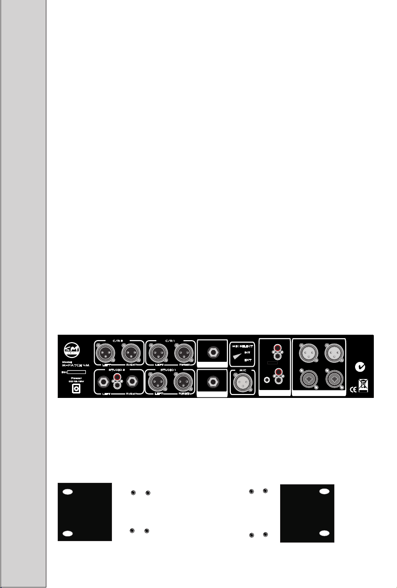
M-PATCH 4M REAR PANEL
Your M-Patch 4M is designed to accommodate a wide variety of balanced and
unbalanced audio connections, allowing for a great deal of flexibility in adapting
the unit for use in almost any studio environment.
Inputs
• Dual L/R Combination Balanced XLR – 1/4” TRS
• Dual L/R Unbalanced RCA
• Dual 1/8” (3.5mm) TRS
• Balanced XLR Talkback Microphone (w/ Built-In Mic Preamplifier)
• TS Talkback Microphone Remote Activator (w/ INT/EXT Selector Switch)
• TS Mute Function Remote Activator
Outputs
• Dual L/R Balanced XLR Control Room Out
• L/R XLR Balanced Studio Out
• L/R 1/4” Unbalanced TS Studio Out
• L/R Unbalanced RCA Studio Out
• 1/8” (3.5mm) TRS Studio Out
Model :
M- Pat ch 4 m
S
ERIAL
Power
DC 12-16V
Lef t
Lef t
C/R 2
Stu dio 2
Rig ht
L
R
Rig ht
Lef t
Lef t
C/R 1
stu dio 1
Rig ht
Rig ht
MUT E RE MO TE
Mic Rem ot e
mic sel ect
int
ext
mic
2
1
AU X in put s
L
2
R
L
R
1
L
Ba la nce d in pu ts
R
n12 25 3
installation
The M-Patch 4M can sit comfortably on your desktop, with all controls within
easy reach. Alternately, the included rack ears can be used for situating the unit
in a standard 19” rackmount configuration.
Page 6

Audio input Connections
The M-Patch 4M features four types of inputs, two of which are balanced and two
of which are unbalanced. The Balanced Inputs feature combination XLR – 1/4” TRS
connectors, while the AUX Inputs feature RCA and 1/8” TRS unbalanced
connectors. All inputs are located on the M-Patch 4M’s rear panel.
SM PRO AUDIO M-PATch 4m
IMPORTANT!
The M-Patch 4M accepts mic or line
level input signals only. Do not connect
your power amplifier outputs to the
M-Patch 4M’s inputs—this will damage
the internal circuitry, and will NOT be
covered under warranty.
Balanced Inputs
The main Balanced Inputs 1 and 2 are ideally suited for connecting to your audio
interface(s) and/or mixer. Simply connect the outputs of your interface to the
1
L
R
2 2
L
R
L
Ba lan ced inp utsAU X inp ut s
1
R
inputs of the M-Patch 4M, and use the rotary volume controls under the Studio 1
and Studio 2 Input Selectors to attenuate the signals as needed. (Note: Set the
attenuators fully clockwise if no attenuation is necessary.)
AUX Inputs
The Aux input channels features two different connector types, ideally suited for
signals from unbalanced devices such as CD players (RCA) and MP3 players or
computer soundcards (1/8” TRS).
NOTE: You can connect up to six different devices to the physical connectors
simultaneously. Use the front panel Studio 1 & 2 and Master Balanced / Aux
selector switches to choose the signal(s) you wish to monitor.
STUDIO 1 & 2
BL1
C/ R
1
100
vO LUM E
BA LAN CE D AU X
BL2
2
St udi o 1
UB1
UB2
1
C/ R
vO LUM E
BL1
100
St udi o 2
BL2
UB1
UB2
2
Mi c
INPUT SELECTORS
(Use to route input signals
to Studio 1 & 2 Ouputs)
CONTROL ROOM 1 & 2
INPUT SELECTORS
(Use to route input signals
to Control Room 1 & 2 Outputs)
STUDIO 1 & 2
VOLUME ATTENUATORS
(Use to control input signal
levels selected for Studio 1 & 2)
Page 7

SM PRO AUDIO M-PATch 4m
AUDIO output connections
Control Room Outputs
The M-Patch 4M has two sets of Control Room (C/R) outputs, each of which will
carry the input signals chosen by the front-panel Control Room 1 and 2 input selector
switches. Use these outputs to route input signals to your monitor speakers. The
levels appearing at the Control Room 1 & 2 outputs can be attenuated using the
front-panel Master rotary volume control. The C/R signal path is totally passive.
Studio Outputs
The M-Patch 4M has two sets of Studio outputs (balanced and unbalanced), each
of which will carry the input signals chosen by the front-panel Studio 1 and 2 input
selector switches. Use these outputs to route your input signals to headphone
systems, to monitoring systems in the recording room, or to any device at which
you want the talkback signal to appear.
Lef t
Lef t
C/R 1
stu dio 1
Rig ht
Rig ht
MUT E RE MO TE
Mic Rem ot e
Model :
M- Pat ch 4 m
S
ERIAL
Power
DC 12-16V
Lef t
Lef t
C/R 2
Stu dio 2
Rig ht
L
R
Rig ht
Output selector switches
Each of the four outputs can be individually
OU TP UT S ELE CTO R
MU TE MU TE
C/ R 1 C/ R 2
Mi c ON
Mi c ON
M - P A T C H 4 M
MU TE MUT E
1010 1000 0
St udi o 1
St udi o 2
muted via their corresponding front-panel
MUTE switches. In addition, the Studio 1 and
Studio 2 output levels can be adjusted using
the Studio 1 and Studio 2 rotary volume
controls. These controls can also be used to
balance the volume of the Studio 1 and 2
signals with the level of the talkback mic.
When talkback is engaged (MIC ON), all
output signals are attenuated by -20dB,
however the talkback mic signal only appears
at the Studio 1 and 2 outputs.
mic sel ect
int
ext
mic
2
1
AU X in put s
L
2
R
L
R
1
L
Ba la nce d in pu ts
R
n12 25 3
Page 8
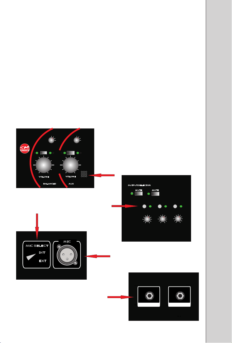
TALKBACK MICROPHONE
The M-Patch 4M features a built-in talkback system. An internal microphone is
provided on the front panel, or you can plug your own microphone into the
balanced XLR microphone input on the rear panel. The INT(ernal) / EXT(ernal)
switch on the rear panel determines which microphone is used for talkback.
Pushing the front-panel MIC ON switch engages talkback. It can also be engaged
via a switch plugged into the rear-panel Mic Remote input.
Talkback level is controlled by the rotary MIC ON volume control. When talkback
is engaged, the signals appearing at the Control Room 1, Control Room 2, Studio 1,
and Studio 2 outputs are attenuated by -20dB. Note, however, that the talkback
mic signal only appears at the Studio 1 and 2 outputs.
SM PRO AUDIO M-PATch 4m
Stu di o 1
BL1
BL2
UB1
UB2
C/ R
1
2
100
vO LUM E
BA LAN CED AU X
INT / EXT MICROPHONE
SELECTOR SWITCH
mi c se lec t
in t
ex t
Stu di o 2
BL1
BL2
UB1
UB2
C/R
1 2
BUILT-IN (INT)
TALKBACK MIC
Mi c
vO LUM E
100
TALKBACK
ON/OFF SWITCH
m ic
TALKBACK REMOTE
CONTROL SWITCH INPUT
OU TPU T S ELE CTO R
EXTERNAL
TALKBACK
MIC INPUT
MU TE MUTE
C/ R 1 C/ R 2
Mi c ON
MU TE MU TE
Mi c ON
St udio 1
M - P A T C H 4 M
Mi c Rem o
1010 1000 0
St udio 2
MU TE RE MO TE
te
Page 9

SM PRO AUDIO M-PATch 4m
mASTER sECTION
The master section provides control over the Control Room outputs. The main
rotary volume control is a passive, precision 12-step film-resistor attenuator,
which provides exceptionally accurate control over volume and left/right balance,
even at very low levels.
Three pushbuttons allow for selection of the input source (Balanced or Aux),
mono or stereo monitoring mode, and Mute All outputs.
BAL AN CED Aux
STE RE O
MON O
-
Ma ste r
All MUT E
0
Headphone amplifier
The built-in headphone amplifier provides monitoring of the selected audio signal.
Two input selector switches allow you to choose between Control Room 1 and 2
and Studio 1 and 2.
Simply connect a pair of headphones to the front-panel TRS headphone output
and use the rotary volume control to adjust the output to the desired level.
WARNING!
You can permanently damage your hearing by monitoring with headphones at
excessively loud levels. Always be sure that the headphone volume control is in
the fully attenuated position (0) before putting on your headphones.
He adp ho ne
ST UD IO
2
C/ R 1
10
0
vO LUM E
Page 10

Using the M-Patch 4m
You can use M-Patch 4M anywhere you want to trim the voltage of, i.e., reduce
the volume of analog audio signals. Other than its primary use as a professional
monitoring controller, you could, for example, use the M-Patch 4M to trim the
output of a microphone preamplifier. With its high-quality potentiometers and
precision film-resistor master attenuator, the M-Patch 4M passes signal more
accurately and with far greater transparency than the built-in volume controls
found on most audio equipment.
You can use the MPatch 4M...
• To A/B between different audio sources
• As a switcher for multiple monitor systems
• To trim the output level of a digital-to-analog converter, such as those found in
high end pre-amplifiers
• As a local volume control for distributed audio systems
• To monitor directly from the outputs of your computer sound card or audio
interfaces without using a mixer, and without degrading bit-resolution by
reducing volume within your DAW
Simple Ideas for Studio Use
Typically you would connect the output of your computer soundcard or audio
interface to the input of the M-Patch 4M via the RCA, TRS, or XLR jacks.
However, you can connect multiple devices as required. For example, your could
connect the outputs of your audio interface to the balanced XLR inputs, and your
soundcard’s mini-jack output to the stereo 3.5mm AUX input. At the same time
you could also connect your CD player or other line level device to the AUX RCA
inputs, and the output of a mixer to the second set of balanced inputs.
Connect XLR cables from the outputs of the M-Patch 4M directly to your active
monitors or the amplifier that powers the monitors. Since you have multiple
outputs available simultaneously, you could easily route a second M-Patch 4M
output to a subwoofer. In this sceario, simply connect the C/R 1 outputs to your
left and right monitor speakers and the C/R 2 output output your subwoofer.
SM PRO AUDIO M-PATch 4m
SMPROAUDIO M-Patch 2
To avoid the bit-degradation that results from lowering the master volume output
of your computer DAW, connect the output of your computer audio interface to an
M-Patch 4M input, and an output of the M-Patch 4M to the input of your powered
studio monitors (or amplifier driving passive monitors). Turn the volume of your
monitors up all the way, set your DAW and audio interface software volume
control panel to 0dB, and use the M-Patch 4M control your monitoring level.
The M-Patch 4M: Simple, effective, transparent!
Page 11

SM PRO AUDIO M-PATch 4m
SMPROAUDIO M-Patch 2
WARRANTY
SM Pro Audio warrants the mechanical and electronic components of this product to be
free of defects in material and workmanship for a period of one (1) year from the original
date of retail purchase, in accordance with the warranty regulations. If any defects occur
within the specified warranty period that are not caused by normal wear or inappropriate
use, SM Pro Audio shall, at its sole discretion, either repair or replace the product.
WARRANTY REGULATIONS
• Warranty is enforceable only by the original retail purchaser.
• Warranty services will be furnished only if the product is accompanied by an original retail
dealer’s invoice. Any product deemed eligible for repair or replacement by SM Pro Audio under
the terms of this warranty will be repaired or replaced at SM Pro Audio’s sole discretion.
• If the product needs to be modified or adapted in order to comply with applicable
technical or safety standards on a national or local level, in any country that is not the
country for which the product was originally developed and manufactured, this
modification/adaptation shall not be considered a defect in materials or workmanship.
• The warranty does not cover any such modification/adaptation, irrespective of whether it
was carried out properly or not. Under the terms of this warranty, SM Pro Audio shall not
be held responsible for any cost resulting from such a modification/adaptation.
• Free inspections, maintenance/repair work, and replacement of parts are expressly
excluded from this warranty, in particular if caused by inappropriate use. Likewise, the
warranty does not cover defects of expendable parts caused by normal wear of the product.
Expendable parts are typically pots, potentiometers, switches and similar components.
• Damages/defects caused by the following conditions are not covered by this warranty:
Misuse and/or abuse; Neglect or failure to operate the unit in compliance with the
instructions given in the user or service manuals; Connection or operation of the unit in
any way that does not comply with the technical or safety regulations applicable in the
country where the product is used;
beyond the control of SM Pro Audio.
Damages/defects that are caused by any other condition
• Repairs and modifications performed by unauthorized personnel will void the warranty.
• Products that do not meet the terms of this warranty will be repaired solely at the buyer's
expense. SM Pro Audio will inform the buyer of any such circumstance. If the buyer fails to
submit a written repair order within 4 weeks after notification, SM Pro Audio will return the
unit C.O.D. with a separate invoice for freight and packing. Such cost will also be invoiced
separately when the buyer has sent in a written repair order.
CLAIM FOR DAMAGES
Failure of SM Pro Audio to provide proper warranty service shall not entitle the buyer to
claim (consequential) damages. In no event shall the liability of SM Pro Audio exceed the
invoiced value of the product.
OTHER WARRANTY RIGHTS
This warranty does not exclude or limit the buyer's statutory rights provided by national
law, in particular, any such rights against the seller that arise from a legally effective
purchase contract.
Page 12

RETURN AUTHORIZATION NUMBER
SM PRO AUDIO M-PATch 4m
To obtain warranty service, you must contact SM Pro Audio for a Return Authorization
number before returning the product (Tel.: +61 3 9555 8081; service@smproaudio.com).
All inquiries must be accompanied by a description of the problem. No products will be
accepted for warranty service without a Return Authorization number
The product must be returned in its original shipping carton, together with the Return
Authorization number, to:
SM Pro Audio Service Department, W25 26-28 Roberna St., Moorabbin, Melbourne,
Victoria, Australia 31892.
If the warranty claim proves to be justified, the product will be returned freight prepaid by
SM Pro Audio within Australia.
Outside of Australia, please contact you local distributor for a Return Authorization
number and shipping instructions.
CLAIM FOR DAMAGES
Failure of SM Pro Audio to provide proper warranty service shall not entitle the buyer to
claim (consequential) damages. In no event shall the liability of SM Pro Audio exceed the
invoiced value of the product.
SPECIFICATIONS
AUDIO INPUTS
Connectors • 4 x Combination XLR – 1/4” TRS
• 2 x stereo RCA pair (L&R)
• 2 x stereo 3.5mm jack
AUDIO OUTPUTS
Output Connectors • 3 x XLR L/R pairs
• 1 x RCA L/R pair
• 1 x 1/4” L/R pair
HEADPHONE OUTPUT
Output Connectors • 1 x 14” TRS stereo
Frequency response • 20Hz – 20Hz +/- 0.5dB
Maximum output level • 320mW into 32
Ù
SMPROAUDIO M-Patch 2
POWER
External • DC12-16V adaptor
PHYSICAL
Dimensions (no rack ears) • 37cm x 15.5cm x 8.5 cm
Net weight • approx. 5Kg
The information contained in this manual is subject to change without notice. No part of this manual may be reproduced
or transmitted in any form or by any means, electronic or mechanical, including photocopying and recording of any kind,
for any purpose, without the express written permission of SM Pro Audio.
All Rights Reserved © 2011 SM Pro Audio
 Loading...