

SMP ZINGO MAGIA X-012/S, ZINGO MAGIA X-012/SD, ZINGO MAGIA X-012/P, ZINGO MAGIA X-012/PD Installation Instructions Manual

INSTALLATION INSTRUCTIONS
MODEL SHOWN = X-012/S
ZINGO MAGIA
X-012/S, X-012/SD, X-012/P & X-012/PD
NO PART OF THIS MANUAL OR DOCUMENT MAY BE COPIED OR RE-PRODUCED IN ANY FORM OR BY ANY MEANS WITH OUT THE EXPRESS
WRITTEN PERMISSION OF SMP (PLAYGROUNDS) LTD.
E: sales@smp.co.uk - W: smp.co.uk - T: +44(0)845 260 1655

INTENTIONALLY LEFT BLANK

© SMP (PLAYGROUNDS) LTD, TEN ACRE LANE, THORPE, EGHAM, SURREY, TW20 8RJ ZINGO X-012
CONTENTS
1 SPECIFICATIONS . . . . . . . . . . . . . . . . . . . . . . . . . . . . . . . . . . . . . . . . . . . . . . . . . . . . . . . . . . . . . . Page 1
2 PREPARATION . . . . . . . . . . . . . . . . . . . . . . . . . . . . . . . . . . . . . . . . . . . . . . . . . . . . . . . . . . . . . . . . Page 1
2.1 ESTABISH ORIENTATION . . . . . . . . . . . . . . . . . . . . . . . . . . . . . . . . . . . . . . . . . . . . . . . . . . . . . Page 2
2.2 MARK OUT HOLES . . . . . . . . . . . . . . . . . . . . . . . . . . . . . . . . . . . . . . . . . . . . . . . . . . . . . . . . . . . Page 2
2.3 ESTABLISH DATUM LEVEL . . . . . . . . . . . . . . . . . . . . . . . . . . . . . . . . . . . . . . . . . . . . . . . . . . . . Page 2
3 PARTS LIST. . . . . . . . . . . . . . . . . . . . . . . . . . . . . . . . . . . . . . . . . . . . . . . . . . . . . . . . . . . . . . . . . . . Page 14
4 INSTALLATION & ASSEMBLY PROCEDURES . . . . . . . . . . . . . . . . . . . . . . . . . . . . . . . . . Page 17
4.1 SAFE WORKING PRACTICE: . . . . . . . . . . . . . . . . . . . . . . . . . . . . . . . . . . . . . . . . . . . . . . . . . . Page 17
4.2 RISKS: . . . . . . . . . . . . . . . . . . . . . . . . . . . . . . . . . . . . . . . . . . . . . . . . . . . . . . . . . . . . . . . . . . . . Page 17
4.3 CONTROL MEASURES: . . . . . . . . . . . . . . . . . . . . . . . . . . . . . . . . . . . . . . . . . . . . . . . . . . . . . . Page 17
4.4 ASSEMBLY METHOD OF CLAMPS TO POSTS. . . . . . . . . . . . . . . . . . . . . . . . . . . . . . . . . . . . Page 17
4.5 INSTALLATION . . . . . . . . . . . . . . . . . . . . . . . . . . . . . . . . . . . . . . . . . . . . . . . . . . . . . . . . . . . . . Page 19
5 POST INSTALLATION INSPECTION . . . . . . . . . . . . . . . . . . . . . . . . . . . . . . . . . . . . . . . . . . . Page 40
Appendix A: . . . . . . . . . . . . . . . . . . . . . . . . . . . . . . . . . . . . . . . . . . . . . . . . . . . . . . . . . . . . . . . . . . . . . . Page 1
1 PLASTIC SLIDE ENTRY FRAME ASSEMBLY . . . . . . . . . . . . . . . . . . . . . . . . . . . . . . . . . . . Page 1
2 PLASTIC SLIDE & PANELS ASSEMBLY . . . . . . . . . . . . . . . . . . . . . . . . . . . . . . . . . . . . . . . . Page 3
ISSUE B
Contents Page 1

ZINGO X-012 © SMP (PLAYGROUNDS) LTD, TEN ACRE LANE, THORPE, EGHAM, SURREY, TW20 8RJ
INTENTIONALLY LEFT BLANK
Contents Page 2 ISSUE B

© SMP (PLAYGROUNDS) LTD, TEN ACRE LANE, THORPE, EGHAM, SURREY, TW20 8RJ ZINGO X-012
1 SPECIFICATIONS
REFERENCE
OVERALL HEIGHT (H) m 2.80
OVERALL LENGTH (L) m 4.50 4.67
OVERALL WIDTH (W) m 3.37 3.74
OVERALL WEIGHT kg 540 590
HEAVIEST PART kg 31.00 91.00
LARGEST PART L x W x H m 2.50 x 0.40 x 0.30 INFORMATION TO FOLLOW
CONCRETE - RUBBER m
CONCRETE - LOOSE FILL m
MINIMUM SPACE L x W x H m 7.50 x 6.83 x 3.70
FALLING SPACE AREA m
IMPACT AREA (WET POUR) m
LOOSE FILL AREA (SAND/BARK) m
MANHOURS hr
MANPOWER
CONSTRUCTIONAL SPACE m 10.00 x 9.00
MAXIMUM FREE FALL HEIGHT m 1.2
3
3
2
2
2
X-012/S X-012/P
ST. STEEL SLIDE PLASTIC SLIDE
0.78 0.77
0.78 0.77
34.63 INFORMATION TO FOLLOW
35.25 INFORMATION TO FOLLOW
37.50 INFORMATION TO FOLLOW
Concrete mix is recommended at:
1 part cement;
2 parts sand;
4 parts aggregate;
by volume with 20mm aggregate
(20 N/mm
2
min compressive strength)
SMP Playgrounds Ltd. recommends an effective Impact Absorbing Surface tested to EN11 77 & BS7188 beneath
this range of play equipment. Refer to manufacturers instructions for details of installation. The surface should have
a Critical Fall Height greater than the Maximum Freefall Height of the equipment. Subject to a risk assessment & for
certain Fall Heights a grass surface may be used.
Constructional Space (shown in the above table) is the approximate working area required to layout and assemble
the equipment.
For the safe operation of this equipment it must be installed on horizontal ground with the required minimum space.
If a loose fill surface is selected for this item it will require a very high level of maintenance to ensure a sufficient
thickness is in place at all times to provide ‘critical fall height’ protection.
The concrete foundations indicated are for average ground. Care should be taken concerning abnormal conditions.
2PREPARATION
All equipment assembly and fixings must conform to EN1176.
Before commencing the installation the surrounding area must be sufficiently fenced and signs erected to warn the
public of the risk of injury.
Tools / ancillary equipment: Plumbline, 10m tape measure, Spirit level, Adjustable set square, Step ladder, Bolt
cutters, 10mm A/F Socket, Torque wrench, 3/16” A/F Allen key.
Minimum Personal Protective Equipment:- Hard hat, Gloves, Armoured boots, Goggles.
ISSUE B
Page 1

ZINGO X-012 © SMP (PLAYGROUNDS) LTD, TEN ACRE LANE, THORPE, EGHAM, SURREY, TW20 8RJ
2.1 ESTABISH ORIENTATION
i) See Specifications for equipments ‘Minimum space’.
ii) Measure out the site to ensure the space required fits into the allotted area, it is horizontal and free from
trip points or other obstructions.
iii) Ensure the equipment is to be provided with an effective Impact Absorbing Surface which has a tested
critical fall height rating greater than the maximum freefall height of the equipment.
2.2 MARK OUT HOLES
Consult SMP layout drawing for structure position on site.
See FIG.3, 4 & 5 for concrete foundation spacings.
NOTE: This is a minimum guide only. Hole excavation should be done progressively as the steelwork is erected.
2.3 ESTABLISH DATUM LEVEL
i) If a rubber tiled Impact Absorbing surface is to be laid, see separate instructions (base may incorporate
up to 2% falls etc.).
ii) If equipment is to sit in loose fill or wet pour rubber surfaces allowances will need to be made for its
recommended thickness. With certain loose fill materials, a greater thickness than 300mm may be
required. This will need to be determined by allowing 100mm for dispersal in addition to the thickness
required for the freefall height of the unit. For installation with a loose-fill type surface all legs on the
structure have be marked with a 'Basic Level Mark' to indicate the recommended 'Finished Surface Level'
of the surface.
Page 2
ISSUE B

© SMP (PLAYGROUNDS) LTD, TEN ACRE LANE, THORPE, EGHAM, SURREY, TW20 8RJ ZINGO X-012
FIG.1
L
W
H
F. S . L .
ISSUE B
Page 3
ZINGO X-012 © SMP (PLAYGROUNDS) LTD, TEN ACRE LANE, THORPE, EGHAM, SURREY, TW20 8RJ
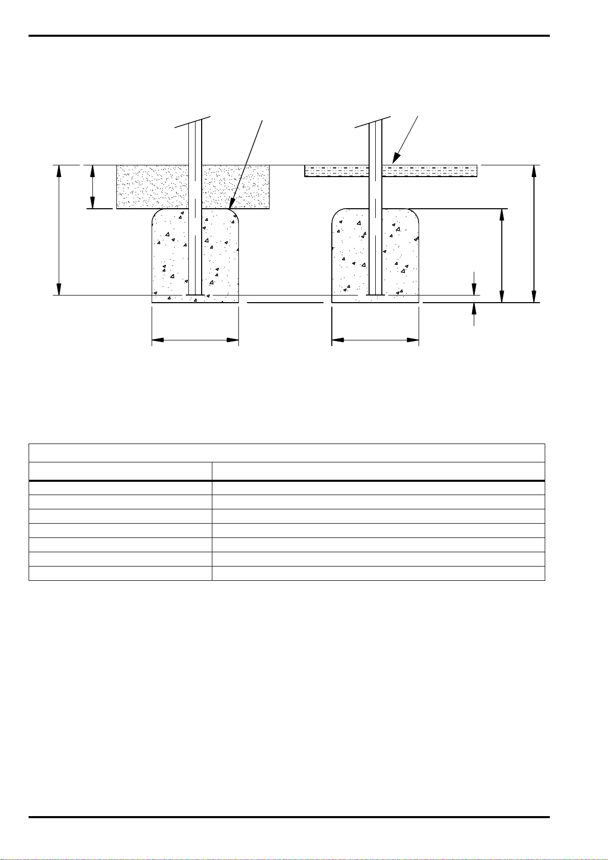
300
50 REF
900
F. S . L .
F. S . L .
LOOSE FILL SURFACE OPTION RUBBER SURFACE OPTION
THICKNESS OF WET POUR
OR RUBBER TILES TO
SUIT 1.30m FALL HEIGHT
FIG.2 EXCAVATIONS FOR LEG FOUNDATIONS
LOOSE FILL
R100 TYP
300 SQ. 300 SQ.
950
650
300mm THICKNESS OF LOOSEFILL SURFACE WILL NEED TO BE CONFIRMED IS SUFFICENT DEPENDING
ON THE SPECIFIC LOOSEFILL MATERIAL SELECTED.
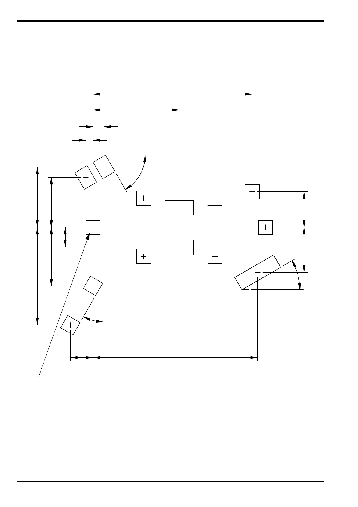
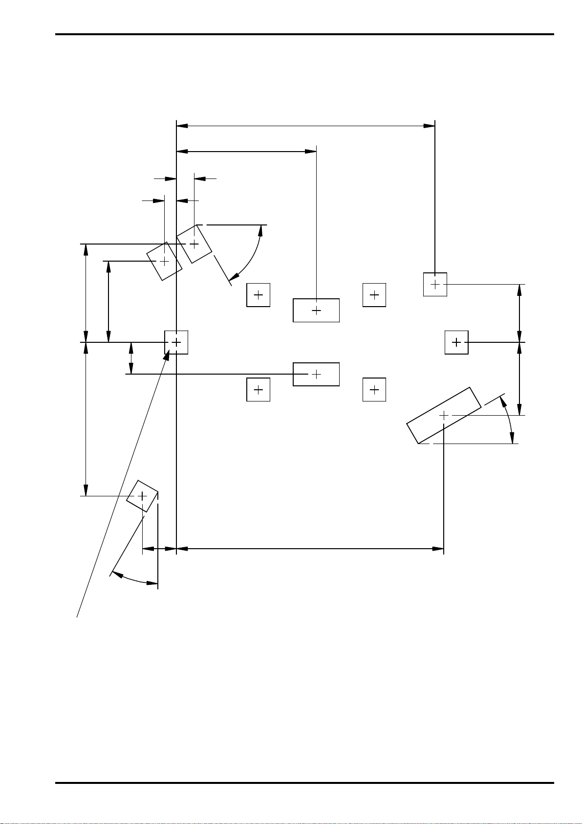
FOUNDATION SIZES FOR FIG.3 & FIG.4
REFERENCE L x W x D
FOUNDATION ‘A’ m 0.30 x 0.30 x 0.95
FOUNDATION ‘B’ m 0.94 x 0.30 x 0.70
FOUNDATION ‘C’ m 0.60 x 0.30 x 0.65
FOUNDATION ‘D’ m 0.40 x 0.30 x 0.70
FOUNDATION ‘E’ m 0.30 x 0.30 x 0.70
FOUNDATION ‘F’ m 0.30 x 0.30 x 0.65
FOUNDATION ‘G’ m 0.30 x 0.30 x 0.80
Page 4
ISSUE B
© SMP (PLAYGROUNDS) LTD, TEN ACRE LANE, THORPE, EGHAM, SURREY, TW20 8RJ ZINGO X-012
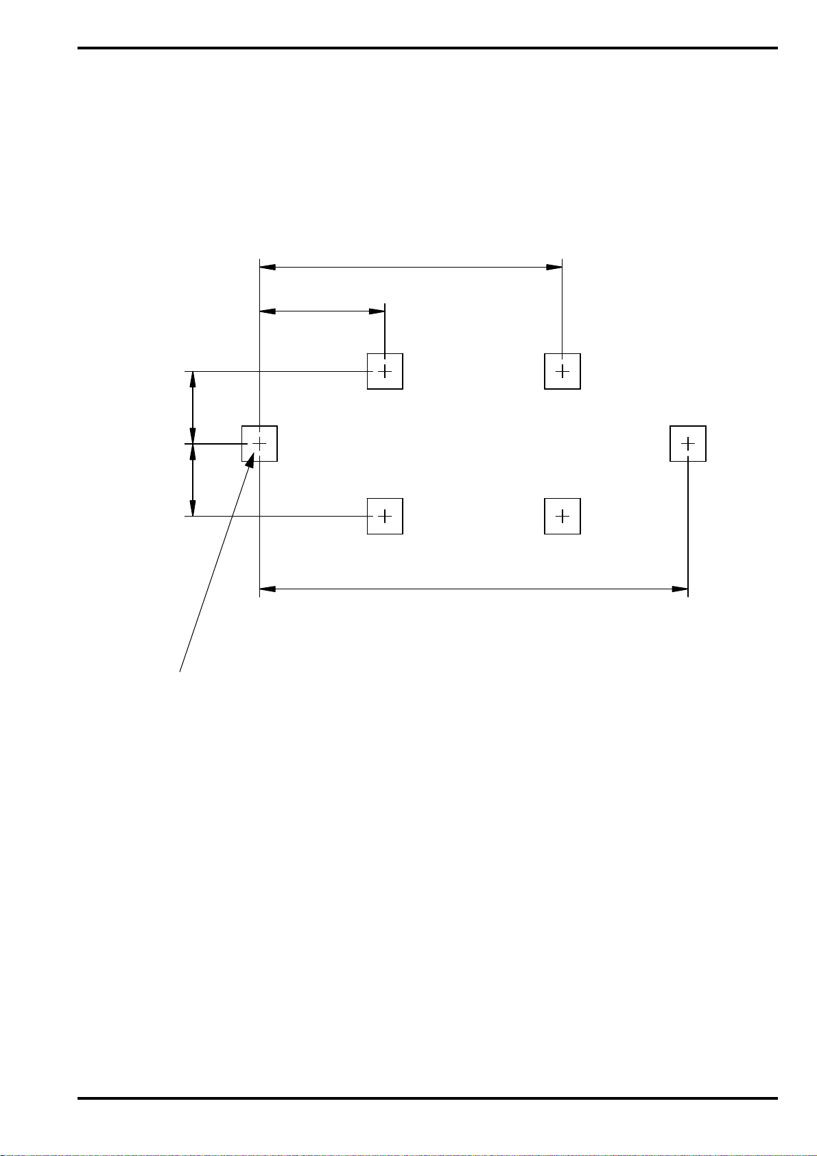
2560
FIG.3
CONCRETE FOUNDATIONS - PRIMARY
ALL DIMENSIONS IN MM
A
STRAIGHT LEG - 1200 DECK
(ITEM 1). WE RECOMMEND
THIS LEG IS INSTALLED
FIRST TO PROVIDE A DATUM FOR
THE REST OF THE STRUCTURE
1060
3620
615
615
A
A A
A
A
ISSUE B
Page 5
ZINGO X-012 © SMP (PLAYGROUNDS) LTD, TEN ACRE LANE, THORPE, EGHAM, SURREY, TW20 8RJ
FIG.4 STAINLESS STEEL CONCRETE FOUNDATIONS - SECONDARY
ALL DIMENSIONS IN MM
STRAIGHT LEG - 1200 DECK
(ITEM 1). WE RECOMMEND THIS
LEG IS INSTALLED FIRST TO
PROVIDE A DATUM FOR THE REST
OF THE STRUCTURE
3345
1050
A
A
A
A
A
A
1810
230
155
3460
480
30°
60°
30°
C
C
E
F
F
D
D
1270
1230
2055
945 750
415
B
Page 6
ISSUE B
© SMP (PLAYGROUNDS) LTD, TEN ACRE LANE, THORPE, EGHAM, SURREY, TW20 8RJ ZINGO X-012
FIG.5
PLASTIC SLIDE CONCRETE FOUNDATIONS - SECONDARY
ALL DIMENSIONS IN MM
STRAIGHT LEG - 1200 DECK
(ITEM 1). WE RECOMMEND THIS
LEG IS INSTALLED FIRST TO
PROVIDE A DATUM FOR THE
OF THE STRUCTURE
REST
3345
1050
A
A
A
A
A
A
1810
230
155
3460
440
30°
60°
30°
C
C
E
G
D
D
1270
1990
945 750
415
B
ISSUE B
Page 7
ZINGO X-012 © SMP (PLAYGROUNDS) LTD, TEN ACRE LANE, THORPE, EGHAM, SURREY, TW20 8RJ
FIG.6
WET POUR AREA - STAINLESS STEEL SLIDE
STRAIGHT LEG - 1200 DECK
(ITEM 1).
1
5
3
7
ALL DIMENSIONS IN MM
1
1
8
0
1
6
8
8
9
8
8
1
4
7
7
1
4
1
7
4
6
9
1
0
8
2
4
1
4
1
5
3
0
1
1
3
5
1
4
0
7
9
8
8
1
1
8
0
4
6
2
5
3
3
9
1
8
0
5
2
8
5
1
5
4
4
8
9
1
1
4
0
7
2
2
1
0
1
4
1
7
Page 8
ISSUE B

© SMP (PLAYGROUNDS) LTD, TEN ACRE LANE, THORPE, EGHAM, SURREY, TW20 8RJ ZINGO X-012
FIG.7
WET POUR AREA - PLASTIC SLIDE
INFORMATION TO FOLLOW
ISSUE B
Page 9

ZINGO X-012 © SMP (PLAYGROUNDS) LTD, TEN ACRE LANE, THORPE, EGHAM, SURREY, TW20 8RJ
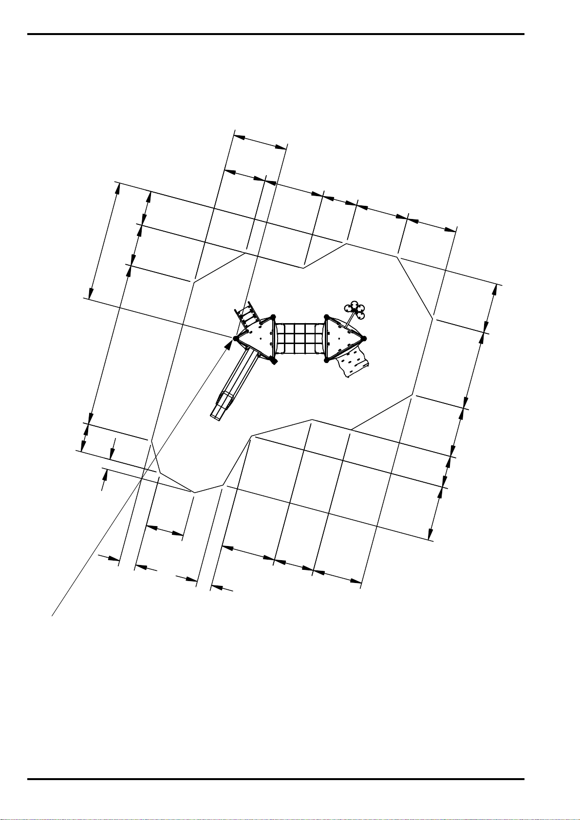
FIG.8
LOOSE FILL AREA - STAINLESS STEEL SLIDE
STRAIGHT LEG - 1200 DECK
(ITEM 1).
1633
2558
ALL DIMENSIONS IN MM
701
1228
4491
1145
1334 3440
813
795
971
1228
3090
1225
556
802
1395
1334
2809
1145
Page 10
ISSUE B

© SMP (PLAYGROUNDS) LTD, TEN ACRE LANE, THORPE, EGHAM, SURREY, TW20 8RJ ZINGO X-012
FIG.9 LOOSE FILL AREA - PLASTIC SLIDE
INFORMATION TO FOLLOW
ISSUE B
Page 11
 Loading...