

SmoothTalker Mobile CX6 4G LTE User Manual

Gain
23 dB
1
50 Ohm
Operating temp
-22 F TO + 185 F
Dimensions
L 4.56 xW 2.15 x H 1.25 (inch)
Model Series
BTUX623
SPECIFICATIONS
2G, 3G, 3G+, 4G, 4G+, GSM, HSPA, CDMA, LTE, LTE A
Frequencies MHz
700 MHz upper 700 MHz lower 850 MHz 1700/2100 MHz 1900 MHz
Max Power-TX: Watts EIRP
Impedence
POWER SUPPLY
12V DC CLA OR 12V DC
fused or 120V AC/DC
Smoothtalker.com
1-877-726-3444
Weight 0.65 lb
6 BAND
Mobile CX6 4G LTE
23dB
Coupling Cradle Connect Cellular
Signal Booster - Extreme Power
MULTI BAND
User Manual
BTUX623
USA
Cellular
Signal Booster
CRADLE TYPE
RX/TX
MULTI BAND 23dB
23dB
6 BAND
GSM,HSPA,CDMA,LTE, LTE A
Coupling Connect
Extreme Power
Band 12,17
Band 13
Band 5
Band 4
Band 2,25
700MHz Upper
850MHz
1700/2100MHz
2G, 3G, 3G+, 4G, 4G+
1900MHz ext
700MHz Lower
Vehicle
stealth
tech
®
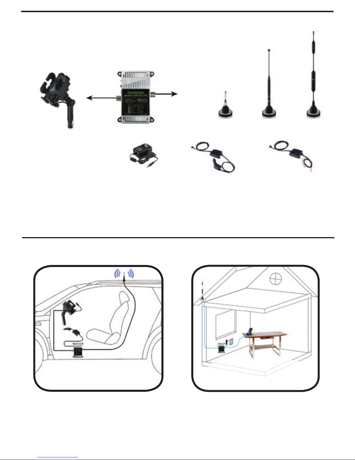
Fig. 2
Desktop Cradle 120 volt
adapter
To comply with FCC rules, this booster must only be operated with cables, antennas
and coupling devices that have been approved for use with this equipment.(Pg. 5)
Applications
Optional Desktop (Fig. 2)
(Additional parts required which are
not included in Booster kit.)
1
Contents
Cellular Booster
12 volt install type12 volt socket plug type120 volt AC/DC
Optional Power Types
Cell Phone Cradle
SEM2MX SEM11MX SEM14MX
NOTE: Only one of the outside antennas is included in this kit (check model) All kits include necessary brackets and co-axial
cables for assembly. It is normal for the booster to be quite warm while the phone is in use state.
Typical Vehicle Installation Mobile CX6 (Fig. 1 )
(All parts are included)
Fig. 1
Mobile Cradle with 12 Volt
Socket CLA plug-in type
Optional outside antenna
SRP1X
2
Installation
1) Connect the outside antenna to the side of the booster
marked as “outside antenna”
Connect the coupling holder to the side of the booster
marked as “inside antenna”
2) Placement
Place the outside antenna in the middle of the vehicle roof. If the vehicle has a
sunroof please place the antenna on the roof towards the back window.
Place the coupling holder in desired location. Connect the booster as shown in
Fig. 1 & 2 on Pg.1 or Fig. 3 on Pg. 4.
Important: Use only the power supply included with the booster. Connecting any
other power supply at any time will result in damage to the booster and will void
the warranty. Do not turn on the power switch until ALL cables have been
screwed or plugged into the booster or you can cause damage to the booster.
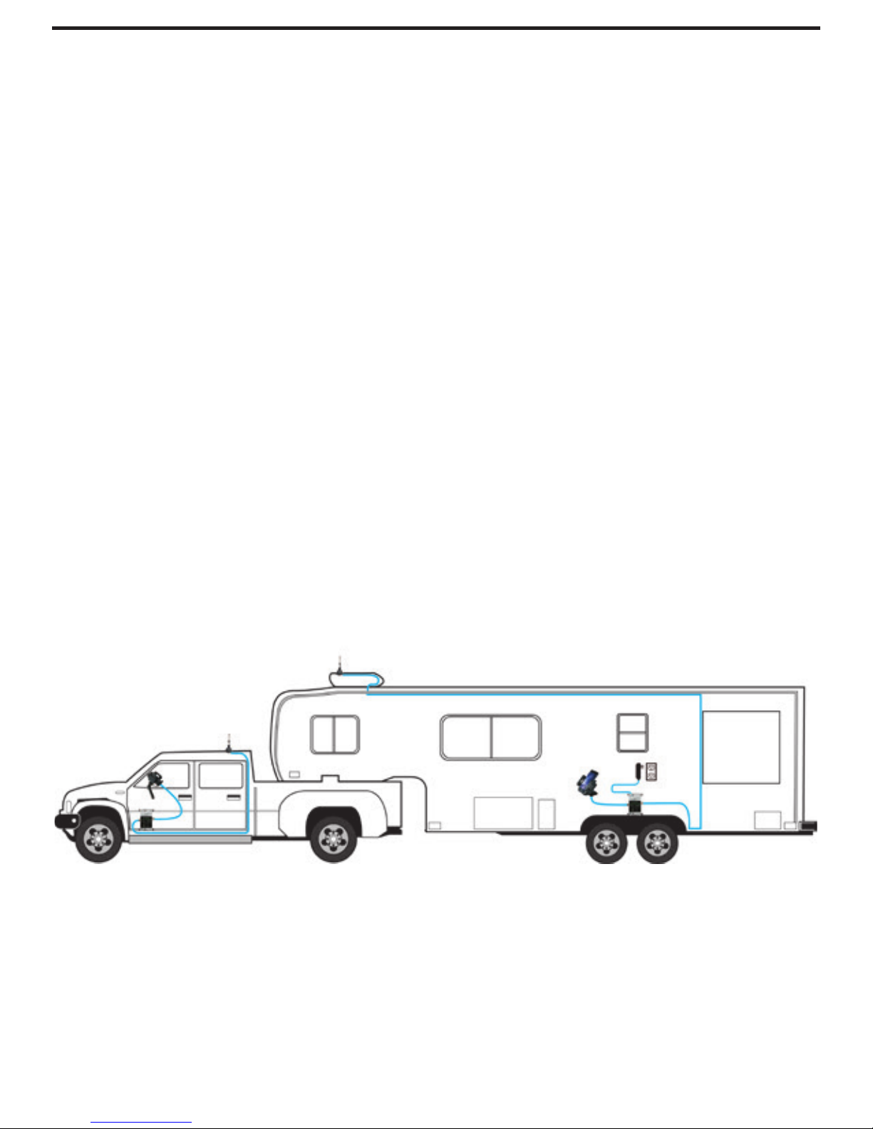
The Mobile CX6
Can easily be moved from vehicle to vehicle
 Loading...