

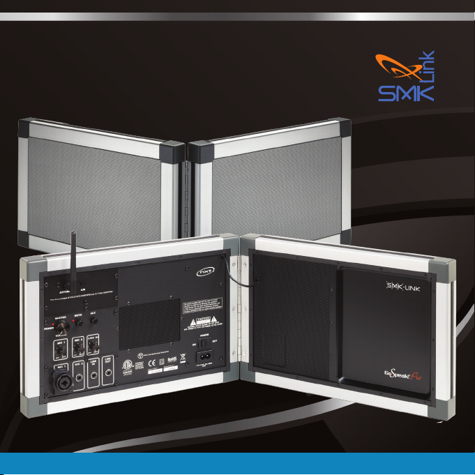
GoSpeak! Pro
Ultra-Portable PA System
™
VP3320
VP3420
VP3520
Page 1
REV. B

Page 2

Introduction
Congratulations on your purchase of the GoSpeak! Pro UltraPortable PA System. is innovative public address system
weighs less than 5 pounds and carries in a laptop tote-bag
(included). Set-up and break down of the GoSpeak! Pro takes
just minutes.
If you’ve purchased the GoSpeak! Pro with Wireless
Microphone (model VP3420) it includes a wireless lapel
microphone. e GoSpeak Pro with Wireless Microphone
(model VP3530) includes a handheld wireless microphone.
Both models feature an integrated microphone receiver.
Additional GoSpeak! Pro Wireless Microphones may be
purchased (Lapel VP3421 and Handheld VP3521) for use with
either model.
e GoSpeak! Pro (model #VP3320) cannot be used with
additional GoSpeak Wireless Microphones, but is compatible
with third-party wireless microphone systems such as the
Audio-Technica PRO 88W-830.
Page 1
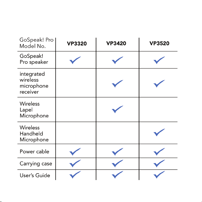
Package Contents
Page 2

Setting up GoSpeak! Pro
Setting up your GoSpeak! Pro takes just minutes. Follow the
steps below:
1. Unfold the GoSpeak! Pro speaker.
2. Plug the AC power cord into your GoSpeak! Pro, and
then into the a 110-120v AC wall outlet.
3. Turn the Master Volume control on your GoSpeak!
Pro all the way counterclockwise (sound o).
Note: avoid turning on your GoSpeak! Pro speaker until you
have connected your microphone.
Page 3

e GoSpeak! Pro Control Panel
Your GoSpeak! Pro control panel is located in the upper le quadrant
of the le speaker (as shown) Components and controls include:
1
Page 4
2
3
6 7 8
9
5
4
10 11 12

1. Wireless microphone antenna and A/B microphone channel selector
(models VP3420 and VP3520 only)
2. Power light LED indicator
3. Master Volume control
4. Speaker MUTE switch with LED indicator
5. An ALC (automatic limiter control) switch
6. MIC 1 input volume control
7. MIC 2 input volume control
8. Line IN input volume control
9. MIC 1 input (combination XLR and ¼” microphone jack)
10. MIC 2 input (1/8” microphone jack)
11. LINE IN input (1/8” stereo input from computer, CD player, etc., or
to receive signal from another GoSpeak! Pro speaker.
12. LINE OUT (1/8” jack to send signal to a recorder or a second
GoSpeak! Pro speaker.
Page 5

Connecting Your Corded Microphone
Your GoSpeak! Pro Speaker has four input/output ports: MIC 1, MIC
2, LINE IN, LINE OUT.
1. Connect your corded microphone into either MIC 1 or MIC 2
inputs and turn the microphone o.
MIC 1 (using with XLR or ¼” phone plug connector).
MIC 2 (using 1/8” phone plug connector).
2. Switch your microphone to the “on” position.
3. Turn on your GoSpeak! Pro Speaker and adjust microphone input
volume.
Note: LINE IN is for connecting music or other input sources
including additional GoSpeak! Pro speakers. e LINE OUT port
is an output source for headphones, voice recorder or to send to
additional GoSpeak! Pro speakers.
Page 6
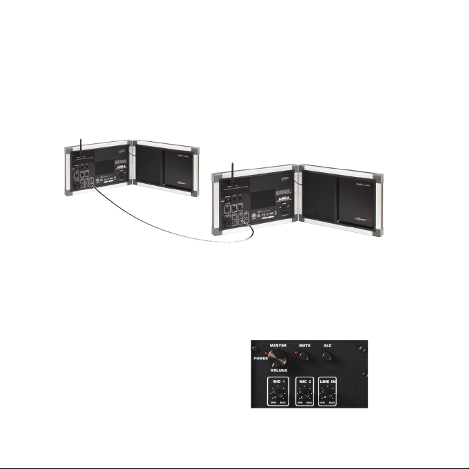
Connecting Multiple GoSpeak! Pro’s
To coconnect multiple GoSpeak! Pro speakers, simply plug in a 1/8”
(3.5mm) audio cable into the LINE OUT jack on the rst GoSpeak!
and the other end into the LINE IN jack on the second GoSpeak! Pro
as shown below:
Input and Speaker Volume Controls
Your GoSpeak! Pro speaker comes with several controls to facilitate
adjusting signal input from your microphone or from other music
sources. Additionally, the speaker has a MASTER Volume control, a
speaker MUTE switch and an ALC (Auto Limiter Control) switch.
e Auto Limiter Control (ALC)
function helps eliminate distortion
caused by microphone
over-modulation.
Master GoSpeak!
LINE OUT
Slave GoSpeak!
LINE IN
Page 7
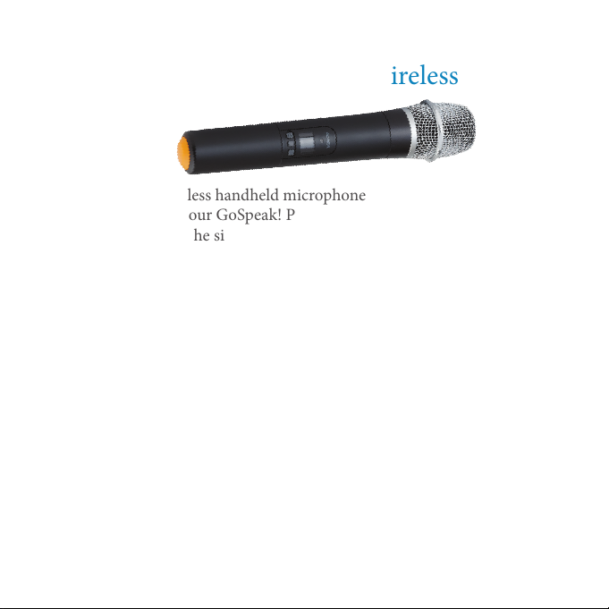
Connecting Your Handheld Wireless
Microphone
Your GoSpeak! wireless handheld microphone is already paired
electronically with your GoSpeak! Pro speaker. To enable the
microphone, follow the six steps below:
1. Install the two AA batteries (included) in your handheld
microphone.
2. Turn your GoSpeak! Pro speaker Master Volume control all the way
counterclockwise (sound o).
3. Turn on your GoSpeak! Pro Speaker.
4. Turn on your wireless microphone using the Power Button on the
microphone.
5.*Match the A or B microphone channel to the GoSpeak! Pro channel.
6. Slowly increase the Master Volume on your GoSpeak! Pro until the
correct microphone volume is established.
*GoSpeak! Pro can only connect to one wireless mic at a time.
Page 8

Microphone Controls and LED Status Indicator
Your GoSpeak! Pro Handheld Microphone has three control buttons
and an LED status indicator. See detail descriptions below.
Channel A/B Switch Button
Unassigned Button (for future development)
Power ON/OFF Button
1. Power Button (le button).
• Toggles power ON and OFF. When power is turned ON, the LED indicator
will ash red and blue for 6 seconds and then, begin ashing BLUE when
mic is on Channel A, or GREEN when mic is on channel B.
• e LED indicator will be dark when power is OFF.
2. Channel Select Button (right button)
• Pressing the Channel Select Button will switch the microphone’s wireless
channel between channels A and B.
• Each time this button is pressed, the LED indicator will ash red and blue for 6
seconds; and then, begin ashing BLUE when mic Channel A is selected, or
GREEN when channel B is selected.
Note: the middle button on the GoSpeak! Pro Handheld Microphone, included for
future development, is currently unassigned.
Page 9
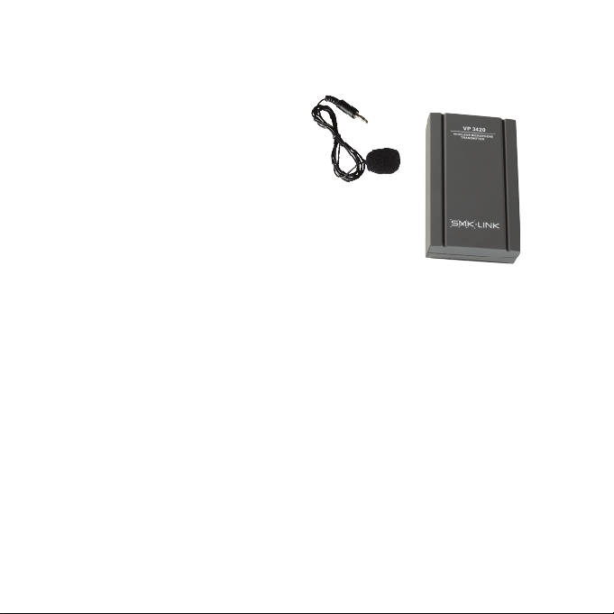
.Connecting Your Lapel Wireless Microphone
Your GoSpeak! wireless lapel microphone is already
paired electronically with your GoSpeak! Pro speaker.
To enable the microphone, follow the six steps below:
1. Install the AA batteries (included) in your lapel microphone transmitter
box.
2. Turn your GoSpeak! Pro speaker Master Volume control all the way
counterclockwise (sound o).
3. Plug your lapel microphone into your transmitter box and turn the box
on.
4. Turn on your GoSpeak! Pro Speaker.
5.*Match the A or B microphone channel to the GoSpeak! Pro channel.
6. Slowly increase the Master Volume on your GoSpeak! Pro until the
correct microphone volume is established.
*GoSpeak! Pro can only connect to one wireless mic at a time.
Page 10

Warranty
SMK-Link Electronics Corporation (SMK-Link) warrants to the original end-user
purchaser of the Product (“you”) that the Product, excluding batteries, will be free
from defects in materials and workmanship under normal use and service for one-year
from date of purchase. If the product becomes defective in materials or workmanship
during the warranty period, SMK-Link will, at its option, either repair or replace it. e
replacement unit may be a more current or upgraded model if the originally purchased
model is not available.
Any Product repaired or replaced under the terms of the warranty is covered for the
remainder of the original warranty period or ninety (90) days from the date of return
shipment, whichever is longer. is warranty does not cover products which have been
subjected to misuse, accident, physical damage, improper installation, abnormal operation
or handling, neglect, inundation or re or when product regulator label has been removed,
altered or rendered illegible; nor does it cover accessory or consumable items.
SMK-Link shall not be liable for any indirect special, incidental, or consequential
damages. SMK-Link’s total liability for damages for any cause related to, or arising out
of, the use or inability to use the product shall not exceed the original price paid for the
product even if SMK-Link has been informed of such possibility.
If your product requires service under warranty, you must rst contact SMK-Link product
support to receive an RMA number. Shipping of defective units back to SMK-Link is at
your expense. e contact information can be found on the SMK-Link website: www.
smklink.com.
is warranty does not aect your statutory rights and you may have other rights which
vary from state to state and country to country. is warranty is understood to be the
complete and exclusive agreement between the parties, superseding all prior agreements,
oral or written, and all other communications between the parties relating to the matter of
this warranty.
e above warranty does not apply to products sold in Australia. Products sold in
Australia by an authorized reseller will contain an Australia specic warranty statement.
Page 11

Regulatory Compliance
FCC Certication
is device complies with Part 15 of the FCC Rules / Industry Canada licence-exempt
RSS standard(s). Operation is subject to the following two conditions: (1) this device may
not cause harmful interference, and (2) this device must accept any interference received,
including interference that may cause undesired operation.
Le présent appareil est conforme aux CNR d’Industrie Canada applicables aux appareils
radio exempts de licence. L’exploitation est autorisée aux deux conditions suivantes
: (1) l’appareil ne doit pas produire de brouillage, et (2) l’utilisateur de l’appareil doit
accepter tout brouillage radioélectrique subi, même si le brouillage est susceptible d’en
compromettre le fonctionnement.
Changes or modications not expressly approved by the party responsible for compliance
could void the user’s authority to operate the equipment.
is equipment has been tested and found to comply with the limits for a Class B digital
device, pursuant to part 15 of the FCC Rules. ese limits are designed to provide
reasonable protection against harmful interference in a residential installation. is
equipment generates uses and can radiate radio frequency energy and, if not installed
and used in accordance with the instructions, may cause harmful interference to radio
communications. However, there is no guarantee that interference will not occur in a
particular installation. If this equipment does cause harmful interference to radio or
television reception, which can be determined by turning the equipment o and on, the
user is encouraged to try to correct the interference by one or more of the following:
• Reorient or relocate the receiving antenna.
• Increase the separation between the equipment and receiver.
• Connect the equipment into an outlet on a circuit dierent from that to which the
receiver is connected.
• Consult a dealer or experienced radio/TV technician for help.
Page 12

MPE Requirements
To satisfy FCC / IC RF exposure requirements, a separation distance of 20 cm or
more should be maintained between the antenna of this device and persons during
device operation.To ensure compliance, operations at closer than this distance is not
recommended.
Les antennes installées doivent être situées de facon à ce que la population ne puisse y
être exposée à une distance de moin de 20 cm. Installer les antennes de facon à ce que le
personnel ne puisse approcher à 20 cm ou moins de la position centrale de l’ antenne.
La FCC des éltats-unis stipule que cet appareil doit être en tout temps éloigné d’au moins
20 cm des personnes pendant son functionnement.
Region Section
Limited by local law regulations, version for North America does not have region selection
option.
Under Industry Canada regulations, this radio transmitter may only operate using an
antenna of a type and maximum (or lesser) gain approved for the transmitter by Industry
Canada. To reduce potential radio interference to other users, the antenna type and its
gain should be so chosen that the equivalent isotropically radiated power (e.i.r.p.) is not
more than that necessary for successful communication.
Conformément à la réglementation d’Industrie Canada, le présent émetteur radio
peutfonctionner avec une antenne d’un type et d’un gain maximal (ou inférieur) approuvé
pour l’émetteur par Industrie Canada. Dans le but de réduire les risques de brouillage
radioélectrique à l’intention des autres utilisateurs, il faut choisir le type d’antenne et
son gain de sorte que la puissance isotrope rayonnée équivalente (p.i.r.e.) ne dépasse pas
l’intensité nécessaire à l’établissement d’une communication satisfaisante.
Page 13

CE Declaration of Conformity
Manufacturer:
SMK-Link Electronics Corporation
3601-B Calle Tecate
Camarillo, CA 93012
is equipment has been tested and found to comply with the limits of the European
Council Directive 1999/5/EC.
A complete Declaration of Conformity can be found at www.smklink.com
Page 14

ank You
ank you for your purchase of the GoSpeak! Pro Ulta Portable
PA System and for choosing SMK-Link Electronics to meet your
presentation needs. We look forward to serving you in the future.
To learn about new SMK-Link products as they become available,
and to ensure the best possible customer support, please register your
product online at www.smklink.com/register.
Support
SMK-Link Electronics Corporation
3601-B Calle Tecate
Camarillo, CA 93012
TEL: (888) 696-3500
FAX: (805) 987-6665
Email: pcsupport@smkusa.com
www.smklink.com
©2014 SMK-Link Electronics Inc. SMK-Link, the SMK-Link logo and GoSpeak! are trademarks
or registered trademarks of SMK-Link Electronics, Inc. All other trademarks are properties of
their respective owners. Made in China.
Page 15

Page 16

Page 17

Page 18
 Loading...