

Page 1
Revised 02.08.11
Installation Instructions:
(Part # SB76880)
XRC Armor Front Fender Kit
WARNING: Check with Local and State laws
before installing this accessory!
NOTE: Carefully read entire instructions thoroughly before attempting to install this part.
Parts Included: Qty
93-5909 Front Fender: Drvr 1
93-5917 Front Fender:
93-5921 Fender Lip Guard:
93-5922 Fender Lip Guard: Pass 1
90-4275 Fender Liner: Drvr 1
90-4276 Fender Liner: Pass 1
93-5923 Outer Duct 2
93-5924 Inner Duct: Drvr 1
93-5925 Inner Duct: Pass 1
90-6745 Hardware Pack: Fender 1
3/8” X 1” SS Button Head Bolt 32
3/8” Flat Washer 32
3/8” Nylock Nut 32
Pass 1
Drvr 1
Parts Included: Qty
1/4”-20 SS Button Head Bolt 12
1/4”–20 SS Nylock Nut 12
10-24 X 3/4” Hex Bolt 3
10-24 SS Nylock Nut 3
90-6746 Hardware Pack: Inner Fender Liner 1
Plastic Retainers 28
90-6747 Hardware Pack: Nutcert 1
3/8” Nutcert 2
90-6774 Hardware Pack: Nutcert Installation 1
96-5951 Nutcert Tool 1
3/8” Star Washer 1
3/8” X 2” Socket Head Bolt 1
3/8” Gr. 8 Flat Washer 1
3/16” X 1” Self Tapping Screw 4
3/8” Gr. 8 Nut:
Un-plated 1
IMPORTANT!: In order to install these fenders the wiper cowl panel and the side cowl panels
must be removed from the vehicle.
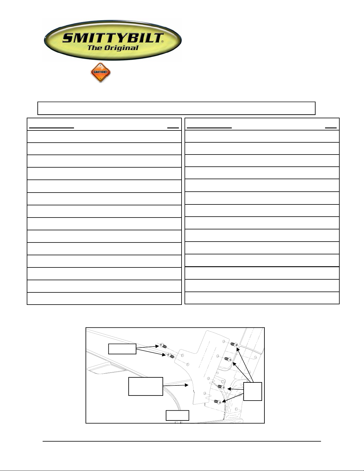
OE Bolts
Windshield
Bracket
(Fig A)
For Technical Support/Warranty Information please call 310-762-9944
Smittybilt, 400 W Artesia, Compton, CA 90220
OE
Bolts
Page 2
INSTALLATION:
Revised 02.08.11
Installation Instructions:
(Part # SB76880)
XRC Armor Front Fender Kit
Side
Cowl
Panel
1/4” Drill
Bit
Inner Fender Structure
Step 1: Working on one side of the vehicle at a time, unbolt and remove the windshield
brackets from the vehicle. Save hardware for reinstallation. (Fig. A)
Step 2: Remove the windshield wipers from the wiper cowl panel.
Step 3: Remove the wiper cowl panel to expose the fender bolts.
Step 4: Fold back the side cowl panel, as if it were hinged on the spot weld seam, to expose
the spot welds. Drill out the spot welds on the side cowl panel to fender seam using a 1/4”
drill bit. Remove the side cowl panel from the vehicle. (Fig. B)
NOTE: Once removed, clamp the cowl panel to a work surface and bend the panel
back to it’s original shape. Save for reinstallation.
Step 5: Unbolt the OE hood catch from the OE fender. Save catch and hardware for reuse.
NOTE: Steps 6 and 7 are for the passenger side fender Only!
Step 6:
Step 7:
for reinstallation. (Fig. I)
Step 8:
reinstallation.
Step 9:
ware for reinstallation.
NOTE: The fenders are spot glued and will require some persistence to remove them.
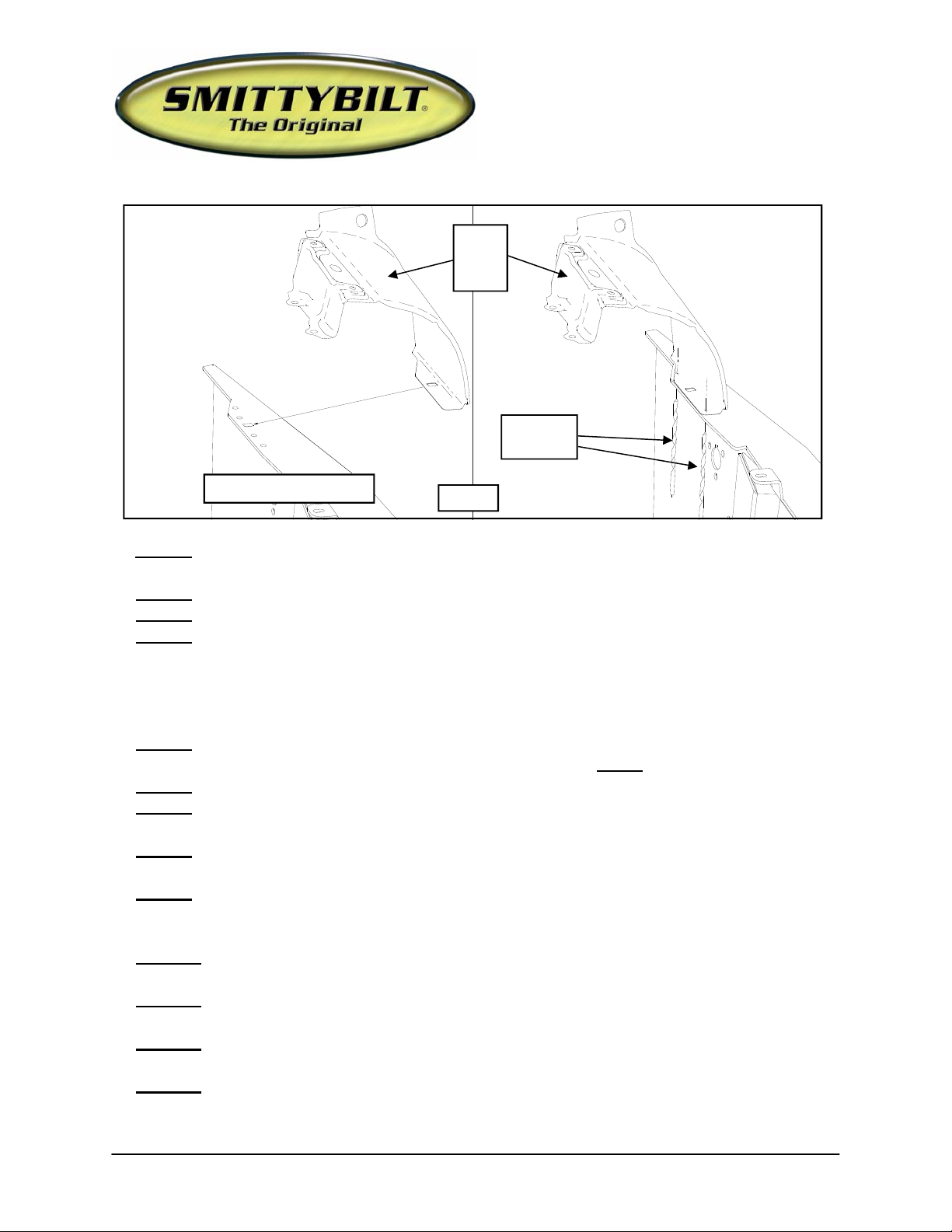
Step 10: Cut the OE fender bracket off the inner fender structure. It will no longer be
needed. (Fig. C)
Step 11:
place and installing a few OE bolts.
Step 12:
a guide and drill a hole through the inner fender structure. (Fig. D)
Step 13:
Unplug the antenna wiring. Loosen and remove the antenna mast. (Fig. I)
Pry the plastic cap off the base and unfasten the antenna base from the fender. Save
Remove the OE inner fender liners from the vehicle. Save The OE Hardware for
Unbolt the OE fender bolts and remove the fender from the vehicle. Save the hard-
Test fit the new fenders (93-5909 drvr and 93-5917 pass) by hanging them in
With the fender in it’s appropriate position, Use the lowest 3/8” wheel well hole as
Remove the fender from the vehicle.
(Fig B)
:
For Technical Support/Warranty Information please call 310-762-9944
Smittybilt, 400 W Artesia, Compton, CA 90220
Page 3
Revised 02.08.11
Installation Instructions:
(Part # SB76880)
XRC Armor Front Fender Kit
Inner Fender Structure
OE
Fender
Bracket
(Fig C)
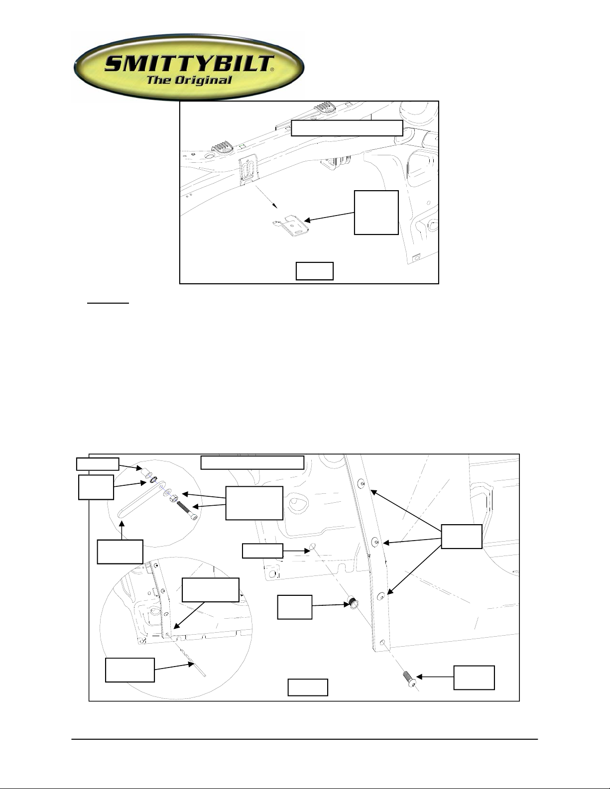
Step 14: Drill out the previously drilled hole in the inner fender structure from 3/8” to 1/2.”
Install the 3/8” nutcert into the 1/2” hole. (Fig. D)
NOTE: If you do not have a professional nutcert installation tool, use the 2 1/2” X
3/8” socket head bolt, 3/8” nut and washer. Install the nutcert into the 1/2” hole on the
vehicle. Thread the nut up as far on the 3/8” bolt as it will go and then follow that with the
washer. Thread the bolt, nut, washer, nutcert tool (96-5951) and star washer assembly
into the nutcert. (Fig. D) While holding the 3/8” bolt with an Allen wrench, tighten the
nut and washer down against the nutcert. Use the nutcert tool and star washer to keep the
nutcert body from spinning while tightening the 3/8” bolt. Once the nutcert is properly
installed into the vehicle remove the 3/8” bolt, nut, washer, nutcert tool (96-5951) and star
washer .
3/8”
Star
Inner Fender Struc-
3/8” X 2 1/2”
bolt, 3/8”
Rivet
Lowest
3/8” &
1/2”
3/8”
(Fig D)
For Technical Support/Warranty Information please call 310-762-9944
Smittybilt, 400 W Artesia, Compton, CA 90220
3/8” X
3/8” SS
Page 4

Revised 02.08.11
Installation Instructions:
(Part # SB76880)
XRC Armor Front Fender Kit
Step 15: Reinstall the fenders (93-5909 drvr and 93-5917 pass) and secure using the previ-
ously removed OE hardware. (Fig. E)
Step 16:
ing the supplied 3/16” X 1” self tapping screws. (Fig. F)
Step 17:
pass) to the fender using the 1/4”-20 X 3/4” stainless button head bolts. (Fig. G)
Step 18: Install the fender lip guard (93-5921 drvr and 93-5922 pass) to the outside of the
wheel well using the supplied 3/8” X 1” stainless button head bolts. (Fig. D)
NOTE: The bottom fender lip guard bolt will align and install into the previously in-
stalled nutcert.
NOTE: Step 19 is for the passenger side fender Only!:
Step 19: Bolt the antenna base to the passenger side fender using the supplied (3) 10-24 X
1” socket head bolts. Reinstall the plastic base cap, reattach the antenna mast and reconnect
Reinstall the previously removed side cowl panel to the inner fender structure us-
Install the outer duct (93-5923) and the inner duct (93-5924 drvr and 93-5925
OE Bolt
Fenders 93-5909
drvr and 93-5917
pass
OE
Fender
Bracket
Inner Fender Structure
Inner Fender Structure
(Fig E)
OE Bolt
3/8” Nutcert
3/8” X 1” SS Bolt
(Fig E)
Fenders 935909 drvr and
93-5917 pass
OE Bolt
OE Bolt
For Technical Support/Warranty Information please call 310-762-9944
Smittybilt, 400 W Artesia, Compton, CA 90220
Page 5

Side
Cowl
Panel
Revised 02.08.11
Installation Instructions:
(Part # SB76880)
XRC Armor Front Fender Kit
3/16” Self
Tapping
Screws
Inner Fender Structure
(Fig F)
the antenna wiring. (Fig. G)
Step 20: The factory inner fender liners will need to be trimmed in order for the Smittybilt
inner fender liners (90-4275 drvr and 90-4276 pass) to provide complete coverage. Trim
the inner fender liner so it has approximately 1” of material sticking out past the front inner
fender structure. This is only a starting point and further trimming may be necessary for a
perfect fit. (Fig. H)
Step 21: Align the (2) large bolt holes in the OE inner fender liner and the supplied inner
fender liner (90-4275 drvr and 90-4276 pass) and install into the inner fender structure using
the (2) previously removed OE bolts. Install the plastic retainers into the outer edge of the
inner fender liner starting from the middle of the fender working outward. (Fig. H)
(6) 1/4”-20
Hardware
93-5924 drvr and
93-5925 pass Inner
Duct
Antenna
Mast
(3) 10-24
Hardware
Antenna Base
(3) 10-24 Allen Head Bolts
Plastic Base Cap
For Technical Support/Warranty Information please call 310-762-9944
Fenders 93-590 9 drvr
and 93-5917 pass
93-5923 Outer
Duct
(6) 1/4”-20” X
3/4” SS Bolts
(Fig G)
Smittybilt, 400 W Artesia, Compton, CA 90220
Page 6

Revised 02.08.11
Installation Instructions:
(Part # SB76880)
XRC Armor Front Fender Kit
Step 22: While holding the inner fender liner into place install the rest of the plastic retain-
ers.
NOTE: The bottom portion of the inner fender liner will be sandwiched between the
body and fender.
Step 23: Reinstall the hood catch to the new fenders using the previously removed OE hard-
ware. (Fig. I)
Step 24: Reinstall the windshield braces to the vehicle using the previously removed OE
hardware. (Fig. A)
Step 25: Repeat the previous steps on the remaining side of the vehicle.
Step 26: reinstall the factory wiper cowl panel using the previously removed OE hardware.
Step 27: Reinstall the windshield wipers.
Step 28: Torque all OE hardware according to manufacturers specifications or the supplied
hardware according to the torque chart below. Installation is now complete.
Cut Off Piece
(2) OE Bolt
Holes
OE Inner
Fender
Liner
(Fig H)
For Technical Support/Warranty Information please call 310-762-9944
Smittybilt, 400 W Artesia, Compton, CA 90220
Page 7

Fenders 93-5909
drvr and 93-5917
pass
OE
Hardware
Revised 02.08.11
Installation Instructions:
(Part # SB76880)
XRC Armor Front Fender Kit
OE Hood
Catch
(Fig I)
Bolt Torque and ID
Decim al System Metric System
All Torques in Ft. Lbs.
Bolt Size Grade 5 Grade8 Bolt Size Class 9.8 Class 10.9 Class 12.9
5/16 15 20 M6 5 9 12
3/83045 M8182327
7/16 45 60 M10 32 45 50
1/2 65 90 M12 55 75 90
9/16 95 130 M14 85 120 145
5/8 135 175 M16 130 165 210
3/4 185 280 M18 170 240 290
T T
D D
L L
1/2-13x 1. 75 HHCS
D T L X
G = Grade (Bolt Strength) P = Property Class (Bolt Strength)
D = Nominal Diameter (Inches) D = Nominal Diameter (M illimeters)
T = Thread Count (Threads per Inch) T = Thread Pitch (Thread Width, mm)
L = Length (Inches) L = Length (M illimeters)
X = Description (Hex Head Cap Screw) X = Description (Hex Head Cap Screw)
Grade 5 Grade 8
(No. of Marks + 2)
G P
M12-1.25x50 HHCS
D T L X
For Technical Support/Warranty Information please call 310-762-9944
Smittybilt, 400 W Artesia, Compton, CA 90220
Page 8

Revised 02.08.11
Installation Instructions:
(Part # SB76880)
XRC Armor Front Fender Kit
Limited Warranties
Smittybilt’s products are covered under the following limited warranties only. Note that the duration of the limited
warranty differs according to the material and finish of the product purchased. Subject to the duration and conditions of the limited warranty stated below, Smittybilt warrants to the original retail purchaser that its products are
free from defects in material and workmanship. All other warranties and representations express or implied, are
hereby disclaimed, including fitness for merchantability and buyer’s intended use or purpose. All parts are sold
“AS IS” except for the limited warranties granted herein. Buyer assumes all risks as to the selection, suitability
and performance of all goods and products selected. This limited warranty does not cover damage or impairment
in any part due to misuse, improper installation, accident or contact with on-road or off-road hazards, product
modification, improper or inadequate cleaning and/or maintenance. Smittybilt is not responsible for items damaged during shipping. This warranty is not transferable from the original buyer. For the original Buyer to be eligible for the limited warranty coverage, the Buyer must provide proof of purchase. Smittybilt strongly recommends
returning the warranty registration card.
Customer’s remedy hereunder shall be limited only to repair or replacement (at Smittybilt’s option) of any defective part(s) returned to Smittybilt at customer’s expense. The determination of whether or not a returned part is
defective or subject to coverage under the limited warranties stated herein shall be made at Smittybilt’s sole discretion.
Duration of Limited Warranty
Limited Lifetime Warranty on Stainless Steel Products -
Smittybilt stainless steel products carry the foregoing limited repair or replacement warranty against workmanship and defects in the material so long as the original purchaser retains the original stainless steel parts.
Limited Five (5) Year / 50,000 Mile Pro-Rata Warranty (whichever occurs first) on Dual-Stage Powder
Coating Products -
Smittybilt dual-stage powder coated products carry the foregoing limited repair or replacement warranty for a
period of (5) years or 50,000 miles (whichever occurs first) from date of purchase against workmanship and
defects in the material, provided that any claim submitted after (2.5) years from date of purchase shall, if accepted, be satisfied by Smittybilt offering customer a credit on the purchase of a replacement product equal to
fifty percent (50%) of customer’s initial purchase price.
Limited Three (3) Year / 36,000 Mile Pro-Rata Warranty (whichever occurs first) on Chrome Products-
Smittybilt chrome products finished carry the foregoing limited repair or replacement warranty for a period of
three (3) years or 36,000 miles against workmanship and defects in the material (whichever occurs first) from
the date of purchase.
To assure product quality, Smittybilt reserves the right to change product design, material, specification and finishes without prior notice to customers. This limited warranty gives you specific legal rights and you may also
have other rights, which may vary from state to state. Some states do not allow limit ations on how long an implied
warranty lasts, so the above limitations may not apply as to you. Also, some states do not allow the exclusion or
limitation of incidental or consequential damages, so the above limitations or exclusions may not apply to you.
Smittybilt reserves the right to discontinue product lines and substitute products, or provide other remedies than
those listed in this limited warranty for those discontinued products.
For Technical Support/Warranty Information please call 310-762-9944
Smittybilt, 400 W Artesia, Compton, CA 90220
 Loading...