

Page 1
Installation Instructions
09 Ford F
-
150 Super Cre
w
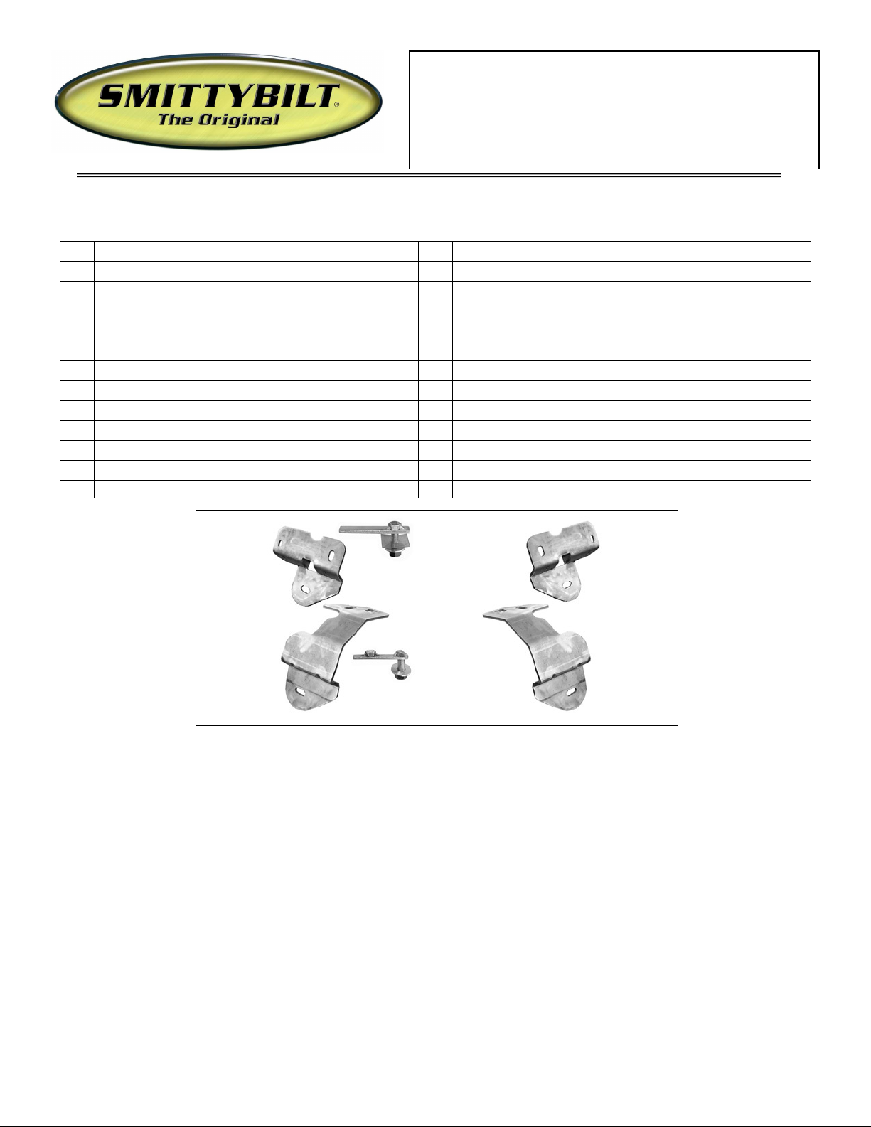
Driver side
Driver side
Passenger
Passenger
12mm x 40mm x 10mm
12mm x 40mm
Sure Step
(Part #FN1990-S4B/FN1990-S4S)
PARTS LIST:
1 Driver/Left Sidebar 4 12mm ID x 30.1mm OD x 3mm Flat Washers
1 Passenger/Right Sidebar 4 12mm Lock Washers
1 Driver/Left Front Mounting Bracket 4 12mm Hex Nuts
1 Passenger/Right Front Mounting Bracket 4 10-1.50mm x 35mm Hex Bolts
1 Driver/Left Rear Mounting Bracket 6 10mm x 30mm OD x 2.1mm Flat Washers
1 Passenger/Right Rear Mounting Bracket 4 10mm Lock Washers
2 12mm x 40mm x 10mm Nut and Bolt Plate 2 10mm Hex Nuts
2 12mm x 40mm Bolt Plates 4 8-1.25mm x 30mm Hex Head Bolts
4 11mm Plastic Retainers 4 8mm ID x 22mm OD x 1.5mm Flat Washers (Outer)
2 9mm Plastic Retainers 4 8mm ID x 17.1mm OD x 1.3mm Flat Washers (Inner)
4 1/2" x 2” Hex Head Bolts 4 8mm Lock Washers
4 1/2” x 1-1/4” OD x 3/32” Flat Washers 4 8mm Hex Nuts
4 1/2” Lock Washers
PROCEDURE:
1. REMOVE CONTENTS FROM BOX. VERIFY ALL PARTS ARE PRESENT. READ INSTRUCTIONS
CAREFULLY BEFORE STARTING INSTALLATION. DRILLING IS REQUIRED. ASSISTANCE
RECOMMENDED.
2. Starting at the front of the driver side of the vehicle, remove the plastic pin, the two small hex bolts and
the metal clips holding the bottom of the fender to the body, (Figure 1A). NOTE: Use a small flat
screwdriver to spread the clip apart for easy removal. Due to body panel misalignment from the factory,
it may be necessary to open these holes slightly with a 3/8" drill bit, (Figure 1B).
3. Next, locate the round and square holes in the floor panel next to the body mount, (Figure 2). Select (1)
12mm x 40mm x 10mm Nut and Bolt Plate and thread (1) 11mm Plastic Retainer part way onto it. Insert
the Nut and Bolt Plate into the square hole in the floor. Line up the nut on the Nut and Bolt Plate with
the round hole. IMPORTANT: The Plastic Retainer is designed to prevent the Bolt Plate from falling
into the body cavity and to aid in mounting the Bracket. After inserting, thread the Plastic Retainer down
side Rear
Mounting
Bracket
side Front
Mounting
Bracket
Nut and Bolt Plate
Bolt Plate
(Pictured with
plastic retainer
attached for
example only)
Rear
Mounting
Bracket
Front
Mounting
Bracket
For Technical Support/Warranty Information please call 310-762-9944
Smittybilt, 400 West Artesia Blvd, Compton, CA 90220
Page 1 of 6
Page 2

Installation Instructions
09 Ford F
-
150 Super Cre
w
Sure Step
(Part #FN1990-S4B/FN1990-S4S)
but leave it loose enough to move the Nut and Bolt Plate around during installation of the Mounting
Bracket. NOTE: For passenger side installation, remove the ground strap next to the mounting holes.
4. Select the driver side front Mounting Bracket and hold it at a slight angle against the body. Move the top
of the Bracket into position with the threaded end of the Nut and Bolt Plate lined up with the T-Slot in
the Bracket. The top of the Bracket is designed to fit snug in position between the body mount and the
lip on the body so it may take a couple of tries to get the Bracket into the correct position, (Figure 3).
Once the top of the Bracket is properly lined up in the T-Slot, rotate the bottom of the Bracket into
position with the holes in the pinch weld. Secure the 12mm threaded end of the Nut and Bolt Plate with
(1) 12mm Flat Washer, (1) 12mm Lock Washer and (1) 12mm Hex Nut. Rotate the Nut and Bolt Plate
around to line up the Nut with the remaining hole and thread (1) 10mm x 35mm Hex Bolt, (1) 10mm Flat
Washer and (1) 10mm Lock Washer into the Nut, (Figure 4). Do not tighten at this time.
5. Align the holes in the pinch weld with the holes in the front Mounting Bracket. Insert (2) 8mm x 30mm
Hex Bolts with (2) 8mm x 22mm OD x 1.5mm Large Flat Washers up from below and secure with (2)
8mm x 17.1mm OD x 1.3mm Small Flat Washers, (to clear the bracket), (2) 8mm Lock Washers and (2)
8mm Hex Nuts, (Figure 5). Do not tighten hardware at this time.
6. Moving to the driver side rear, remove the tape covering the holes on the inner body panel. Select (1)
12mm Bolt Plate and thread (1) 11mm Plastic Retainer part way onto it. Insert the Bolt Plate and
Retainer into the rear mounting hole, (Figure 6A). IMPORTANT: The Plastic Retainer is designed to
prevent the Bolt Plate from falling into the body cavity and to aid in mounting the Bracket, (Figure 6B).
Once the Bolt Plate has been inserted, thread the Plastic Retainer all of the way down to snug up
against the body.
7. Hang the driver side Rear Mounting Bracket from the Bolt Plate and Retainer and secure it with the
included (1) 12mm Lock Washer, (1) 12mm Flat Washer, and (1) 12mm Hex Nut. Insert (1) 10mm x
35mm Hex Bolt, (1) 10mm Flat Washer with (1) 9mm Plastic Retainer into the hole at the rear of the
Mounting Bracket from the outside-in, (Figure 7A). NOTE: The Plastic Retainer is intended to protect
the outer painted surface of the body. Thread the Plastic Retainer onto the Hex Bolt so that it is
between the 10mm Flat Washer and the body, (Figure 7B). Secure the Bracket with (1) 10mm Lock
Washer, (1) 10mm Flat Washer and (1) 10mm Hex Nut. Do not tighten hardware at this time.
8. Attach the Sidebar to the Mounting Brackets using the included (2) 1/2” x 2” Hex Head Bolts, (2) 1/2”
Flat Washers, and (2) 1/2” Lock Washers. Do not tighten hardware at this time.
9. Align the Sidebar and adjust as required. Once properly aligned, tighten all hardware.
10. Repeat steps 2-9 for passenger Sidebar installation. NOTE: For passenger side installation, replace the
ground strap next to the mounting holes for the front Mounting Bracket removed in Step 3.
11. Do periodic inspections to the installation to make sure that all hardware is secure and tight.
To protect your investment, wax this product after installing. Regular waxing is recommended to add a
protective layer over the finish. Do not use any type of polish or wax that may contain abrasives that could
damage the finish.
For stainless steel: Aluminum polish may be used to polish small scratches and scuffs on the finish. Mild
soap may be used also to clean the Sidebar.
For gloss black finishes: Mild soap may be used to clean the Sidebar.
For Technical Support/Warranty Information please call 310-762-9944
Smittybilt, 400 West Artesia Blvd, Compton, CA 90220
Page 2 of 6
Page 3

Installation Instructions
09 Ford F
-
150 Super Cre
w
Insert the Nut and Bolt Plate into
Replace after Bracket installation
R
emove these two
Fig 2
Fig 1A
Fig 1B
Hold the Bracket at an
the Bracket
Hold Bracket in place on
Fig 3
Sure Step
(Part #FN1990-S4B/FN1990-S4S)
Driver Side Installation Pictured
hex bolts, metal clips
and the plastic pin.
Drill a 3/8" hole
through the pinch
weld to clearance
holes if necessary
this square hole and line up the nut
with the round hole. Thread the
plastic retainer only part way down
the threaded end of the bolt. On
passenger side installation, remove
the ground strap for access.
Front
Driver Side Installation Pictured
top of this lip on the body
angle. Insert the top of
the Bracket between this
lip on the body and the
body mount. Line up the
threaded Nut and Bolt
Plate with the T-Slot in
For Technical Support/Warranty Information please call 310-762-9944
Smittybilt, 400 West Artesia Blvd, Compton, CA 90220
Page 3 of 6
Page 4

Installation Instructions
09 Ford F
-
150 Super Cre
w
(2)
8mm x 30mm Hex
Once properly lined up, rotate
Rotate into
(1) 10mm x 35mm Hex
(1) 12mm x 40mm x 10mm
Fig 4
Fig 5
Sure Step
(Part #FN1990-S4B/FN1990-S4S)
position
the Bracket into position and
line up with the holes in the
pinch weld then pull the bolt
through the top of the Bracket
Bolt
(1) 10mm Flat Washer
(1) 10mm Lock Washer
Nut and Bolt Plate
(1) 11mm Plastic Retainer
(1) 12mm Flat Washer
(1) 12mm Lock Washer
(1) 12mm hex Nut
Bolts
(2) 8mm Lock Washers
(2) 8mm x 22mm OD
Large Flat Washers
(outer)
(2) 8mm x 17.1mm OD
Small Flat Washers
(inner against Bracket)
(2) 8mm Hex Nuts
Front
For Technical Support/Warranty Information please call 310-762-9944
Smittybilt, 400 West Artesia Blvd, Compton, CA 90220
Page 4 of 6
Page 5

09 Ford F
-
150 Super Cre
w
1/2” x 2” Hex Bolts
12mm Bolt Plate
with
10mm x 35mm Hex Bolt
Rear bolt on Rear Mounting Bracket
Fig 7A
Thread the Plastic Retainer onto the Bolt Plate
down until it is snug against the body
Fig 6A
Fig 7B
Fig 6B
Driver Side Installation Pictured
Rear
Rear
pictured from outside the vehicle. Place
the Plastic Washer between the 10mm
Flat Washer and the painted surface of
the truck body
Installation Instructions
Sure Step
(Part #FN1990-S4B/FN1990-S4S)
Plastic Retainer
12mm Flat Washer
12mm Lock Washer
12mm Hex Nut
then insert the Bolt Plate into the large hole in
the body. Continue to thread the Retainer
1/2” Lock Washers
1/2” Flat Washers
with Plastic Retainer
(2) 10mm Flat Washers
10mm Lock Washer
10mm Hex Nut
Complete Installation
For Technical Support/Warranty Information please call 310-762-9944
Smittybilt, 400 West Artesia Blvd, Compton, CA 90220
Page 5 of 6
Page 6

Installation Instructions
09 Ford F
-
150 Super Cre
w
Sure Step
(Part #FN1990-S4B/FN1990-S4S)
Cleaning and Maintenance
To protect your investment, wax this product after installing. Regular waxing is recommended to add a protective
layer over the finish. Do not use any type of polish or wax that may contain abrasives that could damage the
finish.
For stainless steel: Aluminum polish may be used to polish small scratches and scuffs on the finish. Mild soap,
window or glass cleaner may be used also.
For gloss black finishes: Mild soap, window and glass cleaner may be used.
LIMITED WARRANTY
Smittybilt (The Company) warrants to the original purchaser of this product that should the product or any part thereof, under
normal use and conditions, be proven defective in material or workmanship within the warranty period of 5 years from the date of
purchase, such defect(s) will be repaired or replaced (At the Company’s option) without charge for parts or labor. To obtain repair or
replacement within the terms of the warranty, the product is to be delivered with proof of warranty coverage ( e.g. dated bill of sale,
receipt), specification of defect, freight pre-paid with Returns Good Authorization Number from Smittybilt to place of purchase. Items
returned to Smittybilt without a Returns Authorization Number will be refused and returned to sender at the senders’ expense.
This warranty does not apply to any product or part thereof which, in the opinion of the Company, has suffered or been damaged
through altercation, improper installation, mishandling, misuse, neglect accident or acts of nature. THE EXTENT OF THE
COMPANY’S LIABILITY UNDER THIS WARRANTY IS LIMITED TO THE REPAIR OR REPLACEMENT PROVIDED
ABOVE AND, IN NO EVENT, SHALL THE COMPANY’S LIABILITY EXCEED THE PURCHASE PRICE PAID BY THE
PURCHASER FOR THIS PRODUCT.
This warranty is in lieu of all expressed warranties and liabilities. ANY IMPLIED WARRANTIES, INCLUDING ANY IMPLIED
WARRANTY OF MERCHANTABILITY SHALL BE LIMITED TO THE DURATION OF THIS WRITTEN WARRANTY. ANY
ACTION FOR BREACH OF ANY WARRANTY HEREUNDER INCLUDING ANY IMPLIED WARRANTY OF
MERCHANTABILITY MUST BE BROUGHTH WITHIN A PERIOD OF 90 DAYS FROM DATE OF ORIGINAL PURCHASE.IN
NO CASE SHALL THE COMPANY BE LIABLE FOR ANY CONSEQUENTIAL OR INCIDENTAL DAMAGES FOR BREACH
OF THIS OR ANY OTHER WARRANTY, EXPRESSED OR IMPLIED,WHATSOEVER. No person or representative is authorized
to assume for the company any liability other than expressed herein in connection with the sale of this product. Some states do not
allow limitations on how long an implied warranty lasts or the exclusion or limitation of incidental or consequential damage, therefore
above limitations may not apply to you. This warranty gives the purchaser specific legal rights. The purchaser may have additional
rights, which vary from state to state.
Some states do not allow limitations on how long an implied warranty lasts or the exclusion or limitation of incidental or
consequential damage, therefore above limitations may not apply to you. This warranty gives the purchaser specific legal rights. The
purchaser may have additional rights, which vary from state to state.
For Technical Support/Warranty Information please call 310-762-9944
Smittybilt, 400 West Artesia Blvd, Compton, CA 90220
Page 6 of 6
 Loading...