

Smith's Heating First Solano Installation, Commissioning And User Manual
1 | SmithsEP.co.uk | Issue 001 - September 2018
Installation, commissioning
and user manual
Unit heater
Solano
Issue 001 | September 2018
ENGLISH | UK | IRL | SmithsEP.co.uk
2 | SmithsEP.co.uk | Issue 001 - September 2018
Technical Documentation waterfan HEATER v201803
1. INTRODUCTION
HEATER heating and ventilation devices are designed to be applied in the buildings of small and medium capacity,
especially such as: production and warehouse halls, car showrooms and service stations, sports halls and stadiums, sacral
buildings and churches, retail stores and wholesales outlets, agricultural facilities, exhibition surfaces.
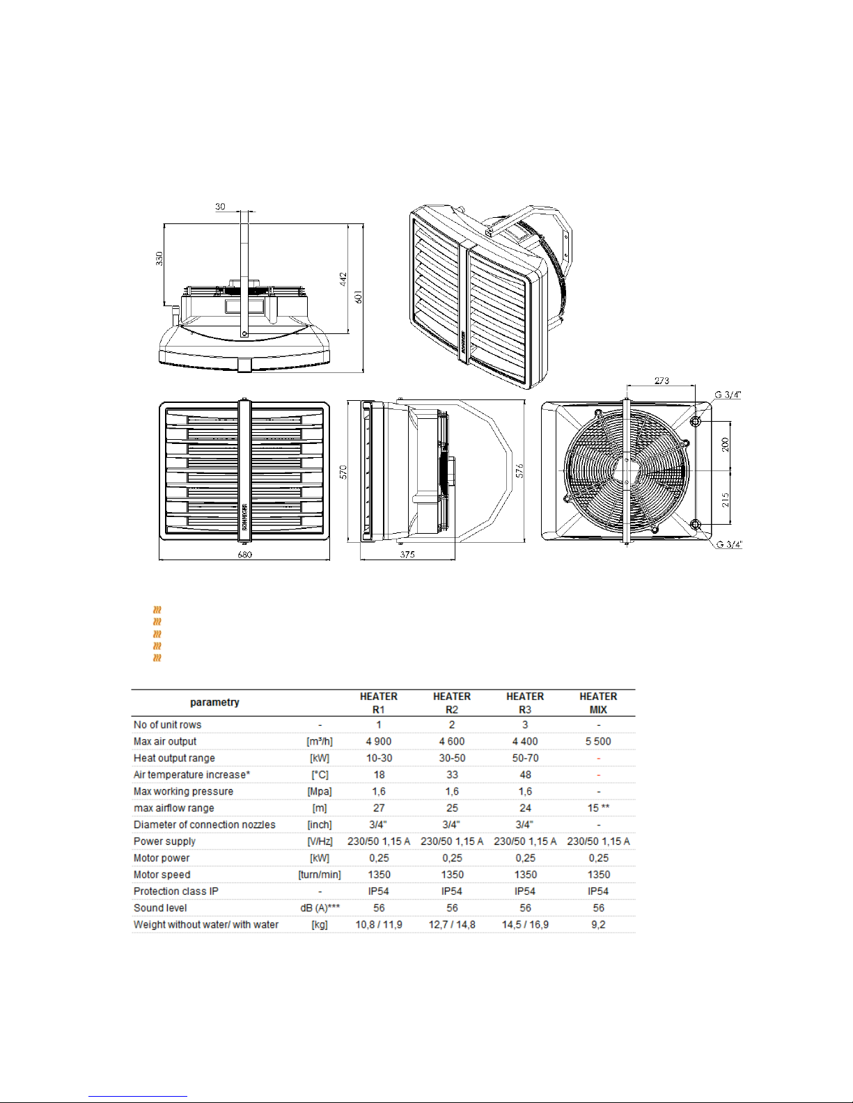
2. DIMENSION AND BASIC TECHNICAL PARAMETERS
Basic elements of HEATER devices :
Casing made of highly resistant EPP (expended polyprophylene) material
Regulated air–conduits
Installation bracket
3 step axial fan 450 mm dimension; fan is protected from direct access to revolving elements with safety netting
Heat exchanger – (Cu/AL) made of copper tubes placed in an aluminum lamellar exchanger /block with stub
connection ½’, ¾”.Stub connections are equipped with air-release valves and heat outlet vent.
*for temperatures of 90/70 and inlet temperature of O˚C
**maximum height of assembly for vertical airflow, max working range of up to 380m². Horizontal range of isothermal stream at
velocity boundary/speed limit of 0,5 m/s
***measurement obtained when 5 m away from the device
3 | SmithsEP.co.uk | Issue 001 - September 2018
Technical Documentation waterfan HEATER v201803
3. GENERAL INFORMATION
HEATER heating and ventilation devices are manufactured in compliance with standards concerning quality, ecology, utility and
work comfort.
HEATER devices are delivered ready-to-use in a cardboard package that is to protect from mechanical damages. The package
consists of: the device, the Manual (Operation and Maintenance Documentation) and Guarantee. If the optional automatic
control ordered, it shall be delivered in a separate package. Make sure all the aforementioned elements are in the package
immediately after the delivery. In the absence of any element, please fill in the suitable carrier document.
4. ASSEMBLY
Prior to any installation procedures, take the following aspects into consideration: easy access for maintenance works, access to
water and electrical installation, appropriate air distribution in a room.
Every HEATER unit is equipped with a set of 3 interchangeable color inserts; in order to change the color, remove the insert
from the front panel and place the desired one back in place.
*It is advisable to mount the device to the wall or the ceiling on original mounting brackets, supporting mount pins (not delivered
with the device) or supporting constructions (shapes and dimensions of the supporting construction may be individually
designed in compliance with durability and strength requirements).
In case of mounting to the ceiling, pay attention to the fact that air-release/venting of the device may be difficult so it is advisable
to place vent at the highest point of the pipework.
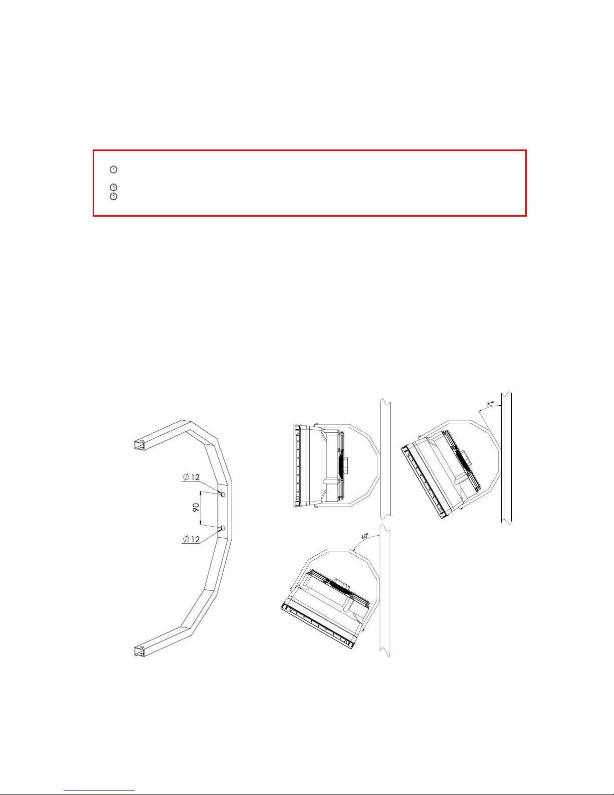
The device may be mounted to the wall with the use of a mounting bracket at the angle of 0°, 30° or 60 °. A mounting bracket
holder is made of curved profile. It has two holes for vertical assembly. Assembly to the wall and/or to the ceiling is possible at
different angles but it requires making necessary holes in the holder.
ATTENTION !
! Przed Before mounting read the manual carefully and adhere to the rules concerning the mounting procedures. Not
applying may result in inappropriate functioning of the device and the loss of the guarantee rights.
! Pay special attention when working with electrical elements of the device.
! Any installation operations must be carried out by qualified persons with appropriate authorizations
4 | SmithsEP.co.uk | Issue 001 - September 2018
Technical Documentation waterfan HEATER v201803
HTG-0001_0 7_z e_s zpilkami
A
A
S
N
T
P
N
3. INSTALACJA ELEKTRYCZNA
NOTICE !
! To sustain proper functioning of the device keep a safe distance– 200mm from its sides and 300 mm from its
backside (from the fan)
Mounting bracket to the heater
The bracket set consist of: a holder, two
sleeves, two M8 screws and washers. In
order to mount the bracket, drill two Ø1213mm holes in places visibly marked on
the casing. Insert sleeves into drilled
holes and place the bracket in. The
included holder must be screwed with M8
screws with washers.
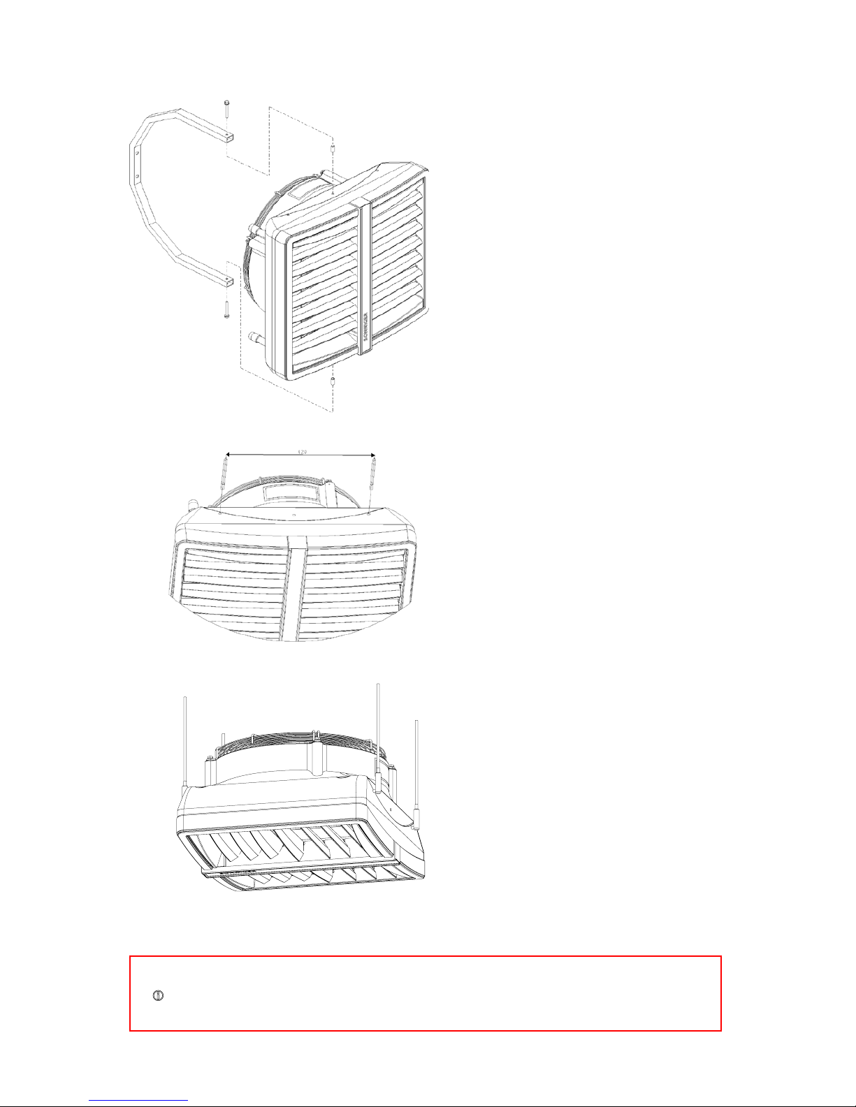
Installation of mounting pins
To mount the heater to the ceiling, use
M8 mounting pins. Drill two Ø8-9mm
holes in places visibly marked on the
casing. Mounting pins may be screwed
into the frame not deeper than 20 mm.
.
Assembly of HEATERMIX air mixer
To mount HEATERMIX air mixer to the
ceiling, use M8 mounting pins. Drill two
Ø8-9mm holes in places visibly marked
on the casing. Mounting pins may be
screwed into the frame of a heat
exchanger to the maximum depth of
20mm. Mounting pins and connecting
elements are not included with the unit.
5 | SmithsEP.co.uk | Issue 001 - September 2018
Technical Documentation waterfan HEATER v201803
5. ELECTRICAL INSTALLATION
The electrical installation and connection to power supply must be done in compliance with the existing regulations and
standards for building industry.
The fan’s engine is equipped with the internal temperature limit fuse protecting the engine from its overheating.
The unit set does not consist of: a feeding cable, a master switch (see diagram)
The electrical installation must be done by an authorized person, acquainted with the Manual. The connection of the feeding
cable and master switch must be done in compliance with electrical diagram (with or without the automatic control, depending
on the option chosen). Any and all damages incurred as a result of the aforementioned causes are not provided with the
Guarantee and the user will be charged with any costs of the device exchange. The connection of the automatic control should
be carried out in accordance with the electrical diagram.
In case of any doubts or problems, unplug the device and contact the device’s installer or SONNIGER Authorized Service.
6. WATER INSTALLATION
The installation of the unit should be done in a way enabling maintenance service; on both stub pipes manual closing valves
should be installed in order to cut off the device. Feeding cables of the heater shall be connected in accordance with the
symbols/marking on the casing (inlet/outlet). In case of electromagnetic valve (with the option of the automatic control) it should
be installed on the outlet as it may be damaged otherwise. When the pipework is being connected to the exchanger, secure the
connections of the heater from oscillating torque (see figure) that may cause leakage in the exchanger.
OUT G 3/4"
IN G 3/4"
WATER DRAIN
AIR VENT
7. AUTOMATIC CONTROL – INSTALLATION
A set of automatic control may be used (powered 230V) that consists of the following:
COMFORT panel – including room thermostat and switch for regulation of 3 speeds of fan. One
COMFORT panel may regulate up to 3 pcs of HEATER units
2-way water valve with actuator; valve should be installed on a return stub of the heater
INTELLIGENT electronic control panel with an automatic speed controller, weekly program and BMS
communication. One INTELLIGENT panel may regulate up to 2 pcs of HEATER units
Splitter MULTI 6 - control up to 6 pcs of HEATER units from one COMFORT or INTELLIGENT Panel
The system is ready to start once the connections between the thermostat and the valve actuator are done, 230V power is
supplied to the thermostat and the fan’s motor is powered by the revs controller.
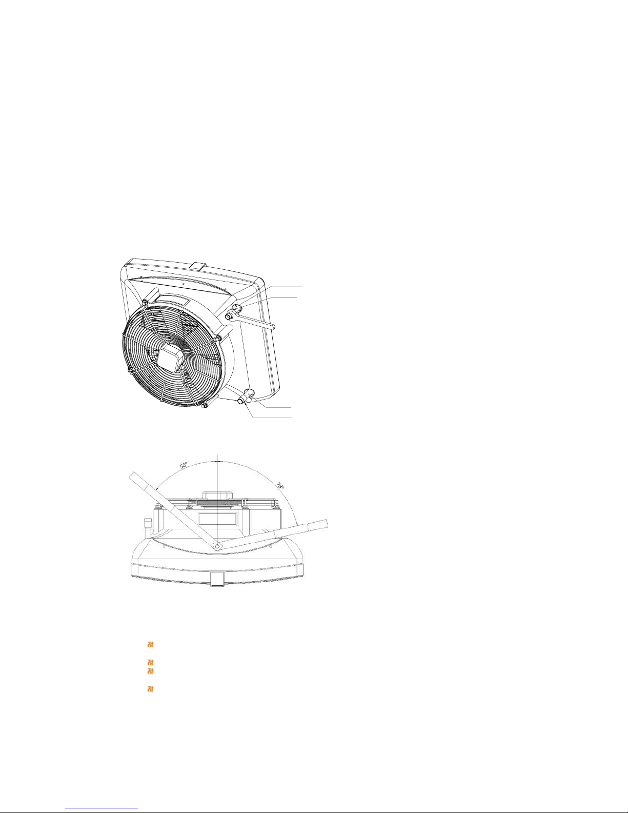
Heating medium
The connector pipes are at the back of the
device. When connecting the hydraulic
pipes/connections, make sure you secure the
connector pipes against rotational torque.
Notice that the connector pipes are not
strained by the pipes. The valve of heating
medium is on the supply pipe and the vent is
on the return pipe.
Use flexible connections to allow the heater to
be turned to the sides. Depending on the
flexible connections, the maximum turn is 78°
to both sides. Figure shows maximum angle to
one side and 50° to the other with minimal
distance left for connections.
 Loading...