

Page 1
Products with this symbol (crossed out wheelie bin) cannot be disposed as household waste.
Old electrical and electronic equipment must be recycled at a facility capable of handling
these products and their waste by-products. If you are purchasing replacement equipment
your retailer may offer a 'take back' scheme, or will be able to give details of the nearest
approved authorised treatment facility. Proper recycling and waste disposal will help conserve
resources whilst preventing detrimental effects on our health and the environment.
WEEE Registered Code : WEE/ED0093VW
This appliance is not intended for use by persons (including children) with reduced physical,
sensory or mental capabilities, or lack of experience and knowledge, unless they have been
given supervision or instruction concerning use of the appliance by a person responsible for
their safety.
Children should be supervised to ensure that they do not play with the appliance.
For Ireland, contact MT Agencies (Ireland) Ltd on Tel: 003 53 1 844 3212
8
June 2016 Issue 2
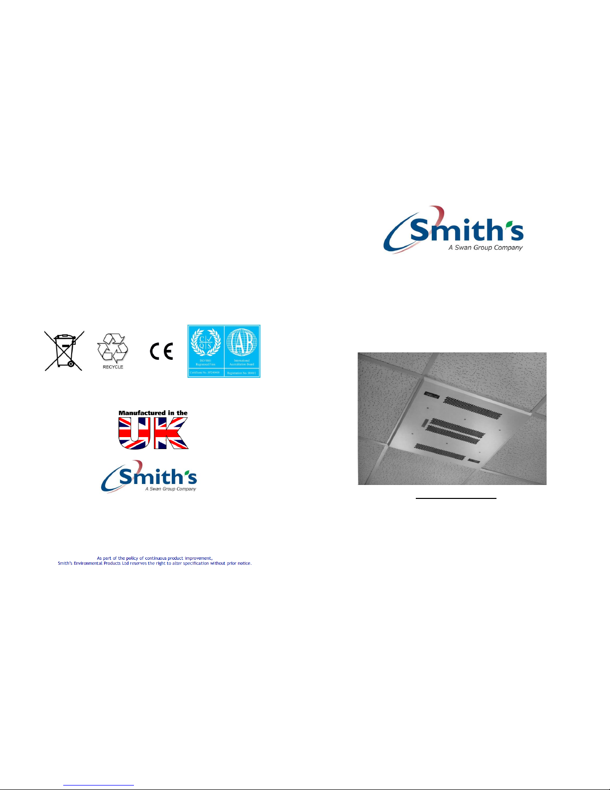
SKYLINE® E 4kW
(Type: FC-E-CL-AC-40)
INSTALLATION & USER GUIDE
February 2014 onwards
USER INFORMATION
This appliance can be used by children aged from 8 years and above
and persons with reduced physical, sensory or mental capabilities or
lack of experience and knowledge if they have been given supervision
or instruction concerning use of the appliance. Cleaning and user
maintenance shall not be made by children without supervision.
DO NOT USE A STANDARD ROOM THERMOSTAT.
ROOMSTAT HAS TO BE 20 AMPS FOR 4kW UNITS
THIS HEATER APPLIANCE MUST NOT BE USED IN BATHROOMS OR
SIMILAR HIGH HUMIDITY AREAS
ISO 9001: 2008
Smith’s Environmental Products Ltd
Blackall Industrial Estate, South Woodham Ferrers, Chelmsford , Essex, CM3 5UW
Tel: 01245 324900 Fax: 01245 324422
Sales: sales@SmithsEP.co.uk General Information E -mail: info@SmithsEP.co.uk Web: www.SmithsEP.co.uk
Page 2

This heater appliance is intended for use as a down draught air heater and can be
mounted directly onto the ceiling or fitted into a 600 mm X 600 mm suspended
ceiling tile frame. It is to be mounted with the underside between 2.5 and 3.0 metres
from floor level. If exceeding 3 metres there will be a reduction in performance.
INSTALLATION.
Preparation.
a) Ensure the mounting surface is capable of supporting this heater appliance and
that the area can provide the installation clearances shown in diagram 1.
b) If installing this heater appliance into a false or suspended ceiling, suitable
suspension chains or rods (6 mm dia., threaded) will be required for attachment
from the top of the heater appliance to the rigid or solid surface above the
mounting area. When using this installation technique, it is recommended the
four fixing points at the top corners of the heater appliance be used to minimise
movement.
c) An installation point for the heater appliance control switch must be selected.
The area must be free from moisture and no higher than 2 metres from the
floor. An electrical cable is required from the power supply to the control switch
and also from the control switch to the heater appliance (see under Electrical
Connections).
d) Remove the facia and fixing screws. Store these in a safe place until required.
e) Remove the screws retaining the side panel marked Electrical Connections and
take out the panel. Store these until required.
To mount the heater appliance direct to the ceiling.
A surface mounting kit is available as an accessory. This kit provides a 135 mm skirt
between the facia and the ceiling.
1. Drill six holes in the ceiling to match 6 (3 per side) of the 14 holes available in
diagram.
Note: The installation clearances given must be kept outside the broken lines
shown. The lines represent the outer edges of the facia panel.
2. Plug the drilled holes according to the ceiling type and construction material.
3. Secure the heater appliance to the ceiling using screws suitable for the
purpose.
4. Refer to the section under Electrical Connections.
5. Replace and secure the panel marked Electrical Connections.
6. Replace the facia and secure with all the original screws.
2
All electrical connections and installations must comply with BS7671 1992,
and the I.E.E. regulations. Check the voltage stated on the heater appliance
is correct for your supply. If in doubt, consult a qualified electrician.
Electrical Connections.
Place and secure a 3 core 2.5mm² single strand interconnecting cable from the
heater appliance location to that of the control switch.
Pass the cable through the heater appliance cable entry facility.
Ensure there is sufficient cable to pass under the cable grip and reach the terminal
block / earth pillar area inside the heater appliance.
Control Switch.
Remove the two screws retaining the switch front panel and lift it off. Remove the
two screws retaining the inner frame and switch from the patress box. Lift out the
frame and switch.
Prepare the patress box for cable entry by selecting the top, bottom or rear facility
for the interconnecting cable and the mains electrical supply cable. Secure the
patress box to the mounting surface and feed sufficient cable through the selected
entry point.
With the three cores of the interconnecting cable, connect the control switch to the
heater appliance as shown in the wiring diagram.
Connect the mains electrical supply cable (3 core, single strand 2.5mm²) via a
switched fused isolator, fused at 20A to the switch panel as shown in the wiring
diagram.
Do not energise the supply until the panels described have been returned and
secured.
Unit Operation.
The wall mounted control switch has 2 positions Off (no fans no heat) and On
(fans and 4kW heat)
Room Thermostat Control.
CAUTION
Ensure room stat rating is compatible with load
(Minimum 4 Amps per Kilowatt (kW).
Refer to manufacturer’s instructions for connections.
7
Page 3

L1
N1
L2
N2
The electrical supply to these units should be via 2.5mm² single strand
3 core cable via a switch fused isolator fused at 20Amps.
6
To mount the heater appliance via suspension rods or chains.
A ceiling tile spacer is available as an accessory. This kit allows the facia to
protrude 85 mm beneath the finished ceiling tile, matching the profile of the
Skyline® CT18 hydronic model. A Surface mounting kit is also available which
provides a a complete four sided trim whne fitted to a solid ceiling.
7. If the mounting area is to align with a false or suspended ceiling panel, then
the holes must be centred to the panel.
8. Cut the suspension chains or rods to the required length for the installation.
Secure to the mounting surface.
9. Secure the lower ends of the chains or rods to the top four corners of the
heater appliance. Adjust the lengths of the chains or rods as necessary to
ensure the heater appliance is true and level.
10. Refer to the section under Electrical Connections.
11. Replace and secure the panel marked Electrical Connections.
12. Replace the facia and ensure it is secured with all the original screws.
3
600
600
248176
426
87
All dimensions in mm.
Page 4

CT4E GRILLE FIXING INSTRUCTIONS
4 5
2 cm Long
2 cm Long
3 X
2 cm Long
3 X
3 X
Align grille panel to heater unit and
secure in position with all 9 screws
provided. Ensure the grille panel
is flat and free from distortions
DO NOT DISTURB THE INNER
COMPONENTS OF THE HEATER UNIT.
 Loading...