

Smith's Heating First Staccato, Sovereign, Sentry, Sentinel, Signature Installation & User Manual
...Page 1

Signature, Sovereign, Sentry, Sentinel, Staccato
Fan-Assisted Radiator
Installation & User Guide
Dear Installer,
The following items should be included in the carton;
• Product complete with pre-wired mains cable
• Mounting Bracket
In the event of items missing or visible damage please contact our After Sales Service on
01245 324560.
We would be most grateful if you would leave this Installation & User Guide and the
Guarantee Registration Card with the owner.
Thank you for your co-operation
Steve Russell
Customer Service Manager
Page 2
2
Introduction
These heaters are primarily intended for installation directly onto a wall at low level. They
must not be installed in bathrooms or other high humidity areas. Please contact us on
01245 324900 for details of products suitable for these applications.
The minimum recommended installation height from the floor to the underside of the
heater is 100mm. The maximum recommended installation height from the floor to the
underside of the heater is 500mm.
A minimum clearance of 75mm is required either side of the heater (except Staccato
models) to allow for the insertion or removal of the outer case fixing screws. No side
clearance is required for Staccato models.
These heaters are designed for use on standard two-pipe pumped central heating systems
with a maximum water temperature of 86°C and a maximum pressure of 6 bar (88lbs/in2).
Pipes are 15mm or 22mm depending on model and either pipe may be used as flow or
return.
These heaters are classified as a fixed appliance and electrical connection should be via a
3A-fused spur. The fused spur must not be directly above the heater but should be
accessible after completion of the installation. All heaters must be earthed.
We recommend the use of full-flow isolating valves. The valves should be accessible after
completion of the installation.
To avoid the possibility of vibration these units must be fitted on a flat even surface.
These heaters are fitted with and controlled by an integral room thermostat. This conforms
to Building Regulations Part L (Part J in Scotland). For further details please contact our
Technical Support on 01245 324560.
Please note the guarantee may be invalidated if this product is not installed and used in
accordance with these instructions.
Installation Guide
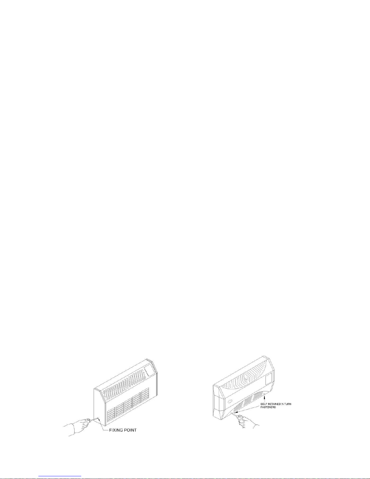
1. Release the outer casing by removing the screws on either side of the casing. For
Staccato models the screws are accessed through the front of the chassis.
Page 3
3
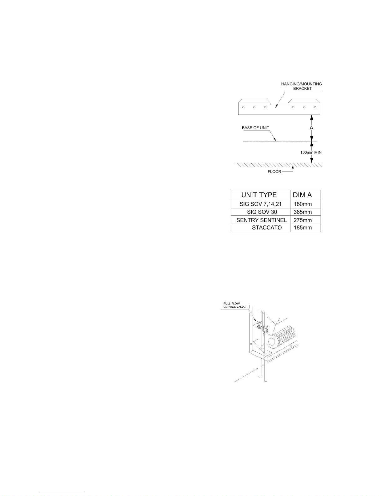
2. Secure the mounting bracket to the wall
using fixings suitable for the wall type. Ensure
the bracket is level and flat to the wall. If
necessary use packing to compensate for an
uneven wall surface. Minimum recommended
installation height is 100mm to the underside
of the heater. Maximum recommended
installation height is 500mm to the underside
of the heater. Hang the heater on the
mounting bracket. Locate all four fixing holes;
two top and two bottom on either side of unit.
Mark the wall through the holes and remove
unit from bracket. Drill a suitable sized hole
through each mark. Hang the heater onto
the bracket and secure with fixings suitable for
the wall.
Signature & Sovereign Models
It will be necessary to remove the bleed screw cover-plate
situated at the top left hand side of the unit above the
supply pipe work. This will enable you to access the top
left fixing hole and at a later stage vent the air from the
unit.
Sentry & Sentinel Models
The mounting bracket does not fit central to the unit. The
mounting bracket should be fixed 20mm to the right of the
centre of the unit.
3. Connect the heating system flow and return
pipes to the heater pipe work. Do not use
soldered fittings to the heater pipe work as the
heat generated could damage internal wiring and
components. We recommend the use of full flow
service valves.
The valves should be accessible after completion of the
installation. Check for water leaks. Remove any
trapped air from the unit via the built in bleed screw
located on the top of the internal supply pipe work.
Signature & Sovereign Models
Refit the cover plate above the bleed screw
Page 4

4
4. Isolate the electrical supply and connect the
heater electric cable to the fused spur (3 amp).
The fused spur must not be directly above the
heater and must be accessible after the
installation is complete.
Commissioning
1. Turn on the electrical supply at the fused spur
2. Turn the thermostat control to maximum. For Signature & Sovereign models the heater
controls are behind the access panel on the right hand side of the heater.
3. Set the controls to Air Circulation setting – see User Guide.
4. Turn on the central heating system
5. Set the controls to Heating – see User Guide.
6. Balance the central heating system if these heaters are installed on the same circuit as
panel radiators
7. If the installation is working correctly remember to reset the thermostat to its normal
setting
Installation Continued
5. Attach the earth bonding connector to the outer casing and refit the outer casing to
the chassis.
6. Please leave this Installation & User Guide with the user for future reference
Page 5

5
Heat Output Performance
Heat Output
∆t 60°C
Heat Output
∆t 50°C
Model Normal Boost Normal Boost
kW (Btu/h) kW (Btu/h) kW (Btu/h) kW (Btu/h)
Signature/Sovereign 7 1.3 (4400) 1.8 (6100) 1.1 (3800) 1.4 (4700)
Signature/Sovereign 14 2.7 (9200) 3.6 (12300) 2.1 (7200) 2.9 (9900)
Signature/Sovereign 21 4.1 (14000) 5.4 (18400) 3.2 (10900) 4.3 (14700)
Signature/Sovereign 30 6.0 (20500) 7.9 (27000) 4.8 (16400) 6.3 (21500)
Sentry/Sentinel 2.5 (8500) 3.4 (11600) 2.0 (6800) 2.7 (9200)
Staccato 2.1 (7200) 3.2 (10900) 1.7 (5800) 2.6 (8900)
∆t 60°C assumes a mean water temperature of 80°C and a room temperature of 20°C
∆t 50°C assumes a mean water temperature of 70°C and a room temperature of 20°C
It is recommended that these models are capable of maintaining the calculated heat loss at
normal heat output enabling the boost setting to be used for faster heat up.
Fault Finding
1. Fan does not run on any switch setting.
a. Check the power supply is switched ON.
b. Check fuse in the fused spur.
c. Check the wiring connections at the fused spur.
2. No heat output.
a. Vent any trapped air from the system (with the system turned OFF).
b. Check the central heating is switched ON.
c. Ensure the thermostat is calling for heat.
d. Balance the central heating system if installed on the same circuit as panel
radiators and increase the circulating pump speed if required.
e. Increase the boiler water temperature.
In the event of difficulty please contact our technical help-line on 01245 324560. It will be
helpful if you do not disconnect the heater from the central heating system.
Smith's Environmental Products Ltd.,
Blackall Industrial Estate, South Woodham Ferrers, Chelmsford, Essex CM3 5UW
Tel: 01245 324900 After Sales: 01245 324560 Fax: 01245 324422
E-mail: info@smiths-env.com Web: www.smiths-env.com
In light of our policy of continuous development Smith’s Environmental Products Ltd reserve the right to alter specifications without prior
notice.
Page 6

6
Signature, Sovereign, Sentry, Sentinel, Staccato
Fan-Assisted Radiator
User Guide
Dear Customer
We are delighted you have chosen our products and trust you are satisfied with the
installation. We would ask you to take a few minutes to read through this User Guide. This
will help you gain maximum benefit from your fan-assisted radiator.
As with all our products your heater is covered by a free five-year parts & labour guarantee
and we would be grateful if you complete and return the Guarantee Registration Card to us
as soon as possible. This will ensure that should you require assistance we can help you
quickly and efficiently.
Thank you for your co-operation.
Steve Russell
Customer Service Manager
01245 324900
Your fan-assisted radiator is designed to operate as part of your central heating system in
the same way as a panel radiator. Providing you leave the heat output switch in either the
normal or boost position it will switch on and off automatically with your central heating
system.
Page 7

7
How a fan-assisted radiator works
Hot water from your central heating
system passes through the heat exchanger
transferring its heat to the aluminium
fins. Cooler air is drawn in by the fan and
heated as it passes over the heat
exchanger before being expelled gently
back into the room. This not only gives a
more even temperature spread but will
heat a room up in less than half the time
of a traditional steel panel radiator.
Fan-assisted radiators include an internal thermostat that prevents the fan from operating
until the central heating system water passing through the heat exchanger reaches 42ºC.
This prevents cooler air being circulated at start up.
Heating - Sentry, Sentinel, Signature/Sovereign 7, 14 & 21 models – see diagram A
Ensure your central heating system is ON. Set the
thermostat control to the desired temperature. For
reference a setting midway between 3 and 4 is
approximately 20°C (68°F). Ensure the fan-only switch is
OFF (out). The position of the fan-only switch may differ
dependant on the model. Set the upper heat-output switch
to I (normal). Providing the water temperature in the
central heating system is more than 42ºC and the
thermostat is calling for heat the product will switch on. If
you require a faster warm up move the heat output switch
to II (boost). Moving the heat-output switch to O will turn off the product.
Air Circulation - Sentry, Sentinel, Signature/Sovereign 7, 14 & 21 models – see diagram A
Ensure you central heating is OFF. Set the thermostat to maximum (7), the heat-output
switch to I or II and push in the fan-only switch. The position of the fan-only switch may
differ dependant on the model. The product will provide a cooling flow of air.
Heating - Signature 30 & Sovereign 30 – see diagram C
Ensure your central heating system is ON. Set the
thermostat control to the desired temperature. For
reference a setting midway between 3 and 4 is
approximately 20°C (68°F). Ensure the upper fan-only
switch is set to RED. Set the lower heat-output switch to
I (normal heat output). Providing the water temperature
in the central heating system is more than 42ºC and the
thermostat is calling for heat the heater will switch on. If
you require a faster warm up move the heat output
switch to II (boost). Moving the heat output switch to O
will turn off the heater.
Page 8

8
Air Circulation - Signature 30 & Sovereign 30 – see diagram C
Ensure you central heating is OFF. Set the thermostat to maximum (7), the heat output
switch to I or II and set the fan-only switch to BLUE. The product will provide a cooling flow
of air.
Heating - Staccato
Ensure your central heating system is
ON. Set the thermostat control to the
desired temperature. For reference a
setting midway between 3 and 4 is
approximately 20°C (68°F). Set the
upper switch to W (winter) and the
lower heat output switch to normal.
Providing the water temperature in the
central heating system is more than
42ºC and the thermostat is calling for
heat product will switch on. If you
require a faster warm up move the heat
output switch to boost. Moving the heat
output switch to O will turn off the
product.
Air Circulation
Ensure you central heating is OFF. Set the thermostat to maximum (7), the heat output
switch to normal or boost and set the Summer / Winter switch to S (Blue) The product will
provide a cooling flow of air.
Fault Finding
This heater is covered by a free five-year parts & labour guarantee. In the event of
difficulty please contact our After Sales Service on 01245 324560. It will be helpful if you
do not disconnect the heater from the central heating system.
Smith's Environmental Products Ltd.,
Blackall Industrial Estate, South Woodham Ferrers, Chelmsford, Essex CM3 5UW
Tel: 01245 324900 After Sales: 01245 324560 Fax: 01245 324422
E-mail: info@smiths-env.com Web: www.smiths-env.com
In light of our policy of continuous development Smith’s Environmental Products Ltd reserve the right to alter
specifications without prior notice.
04-0251 1106
 Loading...