

Page 1
When filling the PWU 2/3 recess unit with system water, it will be necessary to remove the air from it. A built in
manual air vent is accessible on the top left hand side of the unit (this is only accessible with the front cover grille
removed). Using a slotted screwdriver turn counter-clockwise until the air is purged (some water may also be bled
along with the air).
Check to make sure that the PWU 2/3 will receive the flow (GPM) required to achieve it’s duty point, it may be
necessary to balance the system to achieve the desired flow rate.
Electrical. ALL ELECTRICAL CONNECTIONS MUST COMPLY WITH LOCAL AND/OR NATIONAL
CODES AND REGULATIONS. IF IN DOUBT, CONSULT A QUALIFIED ELECTRICIAN.
Remove the electrical junction box cover (situated at the bottom right hand side of the unit) by removing the single
junction box cover screw. Bring supply wiring into the unit through the knockout in the lower right hand-side of the
junction box securing the entry poin t with a connector. Power Supply
Wire should be 14AWG and protected by a 15AMP over current protector. Connect line input to black lead,
neutral to white lead and ground to pillar marked G inside junction box.
Start-up
Set the fan speed switch to either I (low speed) or II (high speed) and activate the system thermostat (field
supplied), because of the integral low limit aquastat, it may take several minutes before the fan is activated. When
the fan does come on, ensure that the switch is operational by moving position to O (off), then to II (high speed).
Best results are obtained by le aving the switch in the I position and reserving II for a quick heat up or in extreme
conditions. If the unit is not operating please refer to the trouble shooting tips at the end of this manual.
Unit operation.
This Pocket Wall Unit has 2 different controls.
1. An internal aquastat, not operated by t he user.
2. A surface mounted rocker switch (si tuated behind the access door) for the user to operate the fan speeds. Min /
Off / Max.
Press “I” for Min. fan speed, press “0” for off, press “II” for Max. Fan speed.
Room thermostat control
This Pocket Wall Unit may be run by a field supplied remote wall mounted room thermostat wired into the power
supply. Refer to the instructions provided with the thermostat selected. One thermostat can be used to control up
to four heater appliances. This filed supplied thermostat should be a line voltage thermostat.
Alternatively, field supply a low voltage room thermostat that would be wired directly to the circulator for the zone
that the PWU units are installed on. On a call for heat, the circulator would come on and the unit mounted
aquatstat would bring the fan on once the coil temperature exceeded the lower threshold.
Unit maintenance
The Smiths Environmental Products PWU 2/3 recess units are designed for years of trouble free operation.
If servicing is required, please contact the installing contractor or
Smiths Environmental Products
Customer Service
300 Pond Street
Randolph, Ma 02368
Phone: 269 925 8818
Troubleshooting tips
If the unit fails to operate:
1. Verify that the supply voltage is 120V AC, all wires are connected and the fan switch is in the I or II position.
2. Verify that hot water is going to and through th e unit at 130°F or above. Both supply and return tubes should be
hot. If the return is not hot, the coil is air locked, which will prevent the fan from operating when unit is set to
heating mode. Bleed air from th e coil if necessary. The unit should run.
3. If the PWU still does not run, replace the aquastat.
Caution:
ELECTRICAL SHOCK MAY RESULT. ISOLATE FROM POWER BEFORE OPENING OR SERVI CING
THIS UNIT
Nov 09 PWU2/3
PWU 2/3
Installation & User Guide
Page 2
The Pocket Wall Unit (PWU) has been designed for a reces sed wall application. The unit should be installed
directly to the studwork by the chassis edge and /or adjustable side mounting brackets set to suit the associated
sheetrock thickness and distance be tween the studs or the unit can be mounted centrally between the studs or
directly to one stud and side mounted bracket used to fix to the opposite stud. The area in front of this unit must
not be obscured or restricted. Vertical surfaces in front of this unit will impede the air flow and reduce it’s capacity.
INSTALLATION PROCEEDURES
Preparation.
Carefully unpack the unit and the top adjustable mounting brackets (x2) from the carton. The front cover grille has
been packed separately and shoul d be stored safely until required.
Fitting centrally between studwork
Mark a distance up from the floor to the desired mounting height. Select the desired thickness of sheet rock to be
used and loosen the screws of the lower adustable mounting bracket and loosely fit the top adjustable mounting
brackets. Measure between the studwork and adjust the brackets to this dimension (D), set the distance between
the top of the studwork and the outer flange of the chassis to that of the sheetrock (E), Place the unit chassis with
the top facing up, level with the mark centrally between the studs when in the correct postion screw the adjustable
brackets to the studwork with suitable wood screws (field supplied) through the six screw holes in the mounting
brackets (two in each flange).
Fitting to left stud.
Mark a distance up from the floor to the desired mounting height. Select the desired thickness of sheet rock to be
used and loosen the screws of the lower adus table mounting bracket and loosely fit a top adjustable mounting
bracket to the top right hand side of the chassis. Measure between the studwork and adjust the brackets to this
dimension (D), set the distance between the top of the studwork and the outer flange of the chassis to that of the
sheetrock (E). Place the unit chassis with the top facing up, level with the mark between the studs when in the
correct postion screw the adjustable brackets to the studwork with suitable wood screws (field supplied) through
the four screw holes in the mounting brackets (two in each flange) and the two screw holes in the chassis
mounting flange.
Fitting to right stud.
Mark a distance up from the floor to the desired mounting height. Select the desired thickness of sheet rock to be
used. Remove the lower adustable mounting bracket and loosely fit a top adjustable mounting bracket to the left
hand side of the chassis. Measure between the studwork and adjust the bracket to this dimension (D), set the
distance between the top of the studwo rk and the outer flange of the chassis to that of the sheetrock (E). Place
the unit chassis with the top facing up, level with the mark between the studs when in the correct postion screw
the adjustable bracket to the studwork with suitable wood screws (field supplied) through the two holes in the
mounting bracket and the two holes in the chassis mounting flange.
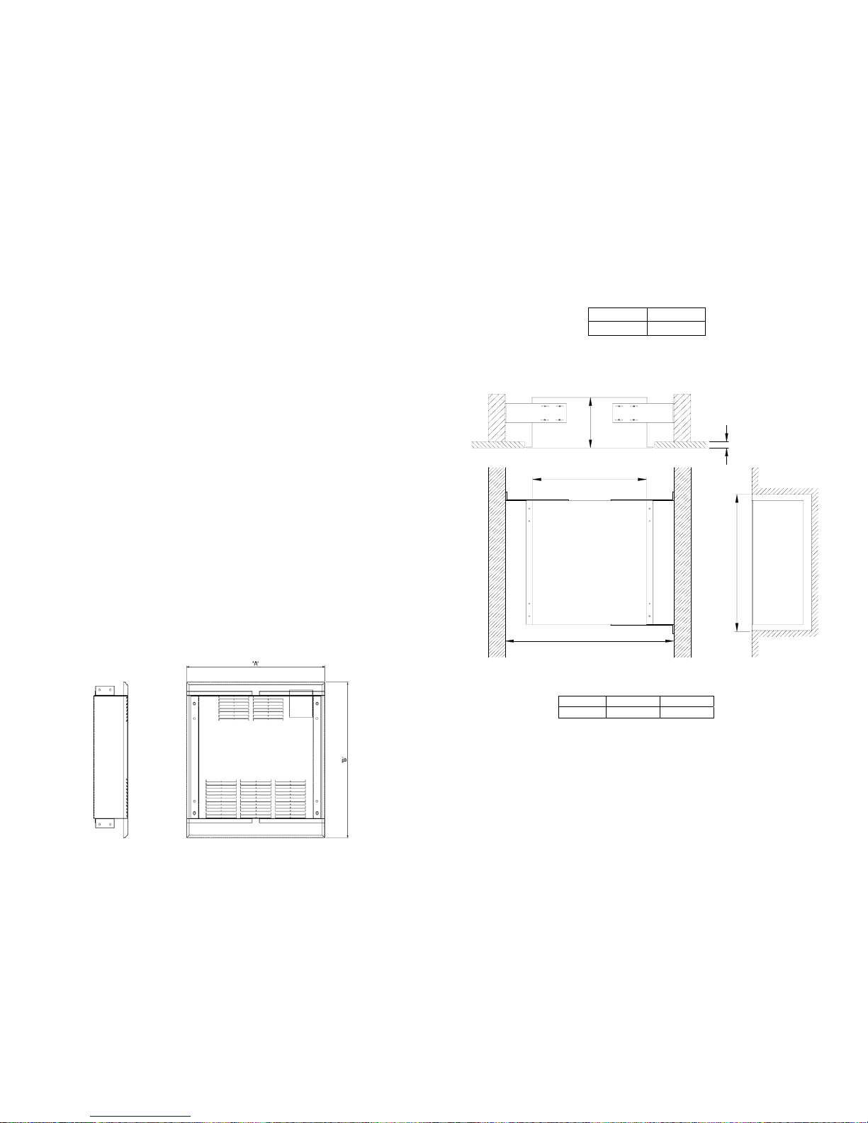
The appropriate size sheet rock can now be fitted around the unit, care must be taken to ensure there is a
½” gap between the top of the unit and the sheetrock. The grille cover will be installed on the chassis
(using the four screws provided) after piping, wiring and air bleeding has been completed.
Table 1
A B
14⅝” 16½”
Note: When fixing unit to st ud work ensure there is a ½” gap between the chassis and the top of the
cut-out. (illustration shows unit mounted centrally between studs, alternatively unit can be fied
directly to studwork on one side and adjustable brackets used to fix other side).
Table 2
Piping Location
Solder the heating system Supply tube to the “back” chassis tube first. Then solder the return line to the “front”
chassis tube. After soldering the Return connection (front tube), check that both connections are leak free.
Note: isolation valves are recommended on both supply and return piping to allow for service and
balancing if necessary.
'C'
'B'
'D'
'A'
'E'
A B C
14½“ 12 ⅛” 3½”
 Loading...