

Smith's Heating First ECOVECTOR LL 1200, ECOVECTOR LL 2000, ECOVECTOR LL 2800 Installation & User Manual
Page 1
IMPORTANT
The appliance is not to be used by children or persons with reduced physical,
sensory or mental capabilities, or lack of experience and knowledge, unless
they have been given supervision or instruction.
Children should not be permitted to play with the appliance.
Ensure that the fan is switched off from the supply mains before removing the
guard.
Any specifications with regards to dimensions of space required for the
appliance to operate effectively
Products with this symbol (crossed out wheelie bin) cannot be disposed as
household waste. Old electrical and electronic equipment must be recycled at a
facility capable of handling these products and their waste by-products. If you are
purchasing replacement equipment your retailer may offer a 'take back' scheme, or
will be able to give details of the nearest approved authorised treatment facility.
Proper recycling and waste disposal will help conserve resources whilst preventing
detrimental effects on our health and the environment.
WEEE Registered Code: WEE/ED0093VW
This Installation and User Guide is printed on 100% re-cycled paper.
Smith’s Environmental Products Ltd.
1-2 Blackall Industrial Estate, South Woodham Ferrers,
Chelmsford, Essex CM3 5UW
Tel: 01245 324900, Fax: 01245 324422, After Sales: 01245 324560
E-mail: info@smiths-env.com
Web: www.smiths-env.com
04-1120 Jan 08
Versatile, energy efficient heating
ECOVECTOR™
Models
LL 1200, LL 2000 & LL 2800
PATENT PENDING
INSTALLATION & USER GUIDE
For latest prices and delivery to your door visit MyTub Ltd - www.mytub.co.uk - info@mytub.co.uk 0844 556 1818
Page 2
INTRODUCTION
In the event of items missing or visible damage please contact us on 01245 324560.
This heating appliance is intended for mounting on a wall at low level. The minimum
recommended installation height is 150cm (6 inches) from the floor. There is no
clearance required on either side of the heater.
This heater must not be used in bathrooms or other high humidity areas.
Ecovector™ is designed for use on standard two-pipe pumped central heating
systems where the system hot water is generated from either a boiler or renewable
sources. This product is not suitable for one-pipe heating systems. Pipe connections
are 15mm.
We recommend the use of full flow isolating valves. These valves should be
accessible after completion of the installation.
Ecovector™ is classified as a fixed appliance and electrical connection should be via
a double pole 3A fused spur. The fused spur must not be directly above the heater
but should be accessible after completion of the installation. If the pre-wired mains
cable is damaged, it must be replaced by the manufacturer, its service agent or
similarly qualified persons. The appliance must be earthed.
To avoid possibility of vibration, this product must be installed on a flat, even surface.
To comply with Building Regulations Part L (Part J in Scotland) this heater is fitted
and controlled by an integral room thermostat
Please note the guarantee may be invalidated if this product is not installed
and used in accordance with this guide.
MOUNTING THE UNIT
Remove the EZ hanger from the back of the heater. Remove screws from the
underside of the front panel, carefully lift up and remove.
2
Ecovector™ includes a selectable low temperature thermostat that prevents the
fan(s) operating until the central heating system water passing through the heat
exchanger reaches a set temperature.
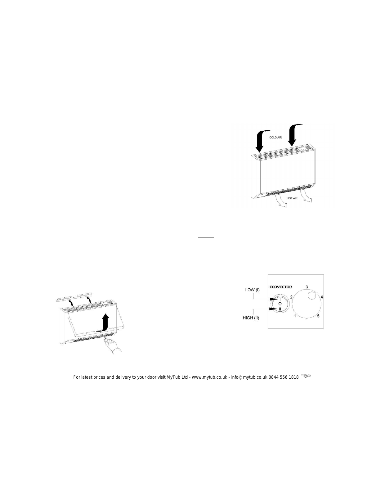
Heating
Ensure your central heating is ON, the heat output switch set to Low (I) and the
thermostat set to the required position (position 3 is approximately 20°C).
If you require a faster warm up set the heat output switch to High (II)
7
For latest prices and delivery to your door visit MyTub Ltd - www.mytub.co.uk - info@mytub.co.uk 0844 556 1818
Page 3

FAULT FINDING
Fan does not run on any switch setting
• Check the power source is switched ON
• Check fuse in the fused spur
• Check wiring connections at the fused spur
No heat output on settings I and II
• Check the power supply is switched ON
• Ensure the room thermostat is calling for heat
• Check the heat source switch is in the correct mode
• Balance the central heating system if installed on the same circuit as panel
radiators and increase the circulating pump speed if required.
• Increase the heat source water temperature
In the event of difficulty please contact us on 01245 324560. It will be more helpful if
you do not remove the product from the central heating system.
We would be most grateful if you would leave this installation & operation guide and
the guarantee registration card with the owner of the property.
USER GUIDE
Your product is covered by a free 5-year parts and labour guarantee; please
complete and return the Guarantee Registration Card to us as soon as possible to
ensure that should you require assistance, we can help you quickly and efficiently.
Your Ecovector™ is designed to operate as part of your central heating system in the
same way as a panel radiator. Providing you leave the heater switches in their
normal operating positions it will switch on and off automatically with you central
heating system.
Heat from your central heating system passes through a heat exchanger transferring
its heat to the aluminium fins, room air is drawn in the top grille and heated as it
passes through the heat exchanger before being gently expelled back into the room
at floor level.
6
Fix the EZ hanger to the wall, position the heater on the EZ hanger and secure to the
wall at the five fixing points.
PIPE WORK
We recommend the use of full flow isolating valves. These valves should be
accessible after completion of the installation. Pipe work can be brought out from the
heater directly or through the rear chassis. A lower panel blanking plate is packed
and supplied with the heater if the latter option is used (to fit this remove the 3 screws
from the fitted slotted pipe access panel and replace with the blanking plate).
Connect the heating system flow and return pipes to the heater pipe work. Do not
use soldered fittings to the heater pipe work as he heat generated could damage
internal wiring and components. The pipe nearest the front of the heater is the supply
flow and the pipe nearest the chassis is the return.
Check for water leaks. Remove any trapped air from the system via the vent valve
on the top left hand side of the heat exchanger. Do not over tighten the air vent
3
For latest prices and delivery to your door visit MyTub Ltd - www.mytub.co.uk - info@mytub.co.uk 0844 556 1818
Page 4

ELECTRICAL CONNECTION
ALL ELECTRICAL INSTALLATIONS CONNECTIONS MUST COMPLY WITH
BS7671, 1992 AND THE IEE REGULATIONS. CHECK THE VOLTAGE ON THE
HEATER IS CORRECT FOR YOUR SUPPLY. IF IN DOUBT, CONSULT A
QUALIFIED ELECTRICIAN.
If the pre-wired mains cable is damaged, it must be replaced by the manufacturer, its
service agent or similarly qualified persons.
Isolate the supply and connect the heater three core mains lead to the fused spur
(3A) in accordance with the instructions provided on the mains lead label. (The
supply wire which is coloured green or green and yellow must be connected to the
terminal marked E on the appliance, the supply wire which is coloured black or blue
must be connected to the terminal marked N on the appliance and the supply wire
which is coloured red or brown must be connected to the terminal marked L on the
appliance).
The fused spur must not be directly above the heater but should be accessible after
completion of the installation.
COMMISIONING
This heater is equipped with a selectable low temperature cut out thermostat which
requires the correct system hot water to be sensed before the fan(s) will run. The
heat source switch can be set to run on either renewable (+38°C) or boiler mode
(+52°C).
Set the heat source switch to the correct mode, turn on the electrical supply at the
fused spur, switch on the central heating system, set the thermostat and the heat
output switch to Low (I) or High (II). The fan(s) should run and heat will flow within a
few minutes.
4
If this heater is installed on the same circuit as panel radiators balance the central
heating system.
When the installation is working correctly, remember to reset the room thermostat to
its normal setting.
INSTALLATION COMPLETION
Attach the earth bonding connector to the outer casing and refit the outer casing to
the chassis.
HEAT OUTPUT PERFORMANCE
It is recommended that the Ecovector™ model is capable of maintaining the
calculated heat losses at Low (I) heat output enabling High (ll) to be used for faster
heat output.
Notes
∆t60°C assumes a mean water temperature of 80°C and room temperature of 20°C
∆t50°C assumes a mean water temperature of 70°C and room temperature of 20°C
∆t20°C assumes a mean water temperature of 40°C and room temperature of 20°C
5
Ecovector™ LL 1200 Ecovector™ LL2000 Ecovector™ LL 2800
∆∆∆∆t
Low (I)
Btu
(kW)
High (II)
Btu
(kW)
Low (I)
Btu
(kW)
High (II)
Btu
(kW)
Low (I)
Btu
(kW)
High (II)
Btu
(kW)
20°C
1200
(0.4)
1600
(0.5)
2500
(0.7)
2900
(0.9)
3200
(1.0)
4200
(1.2)
50°C
3400
(1.0)
4300
(1.3)
5500
(1.6)
7600
(2.2)
8000
(2.3)
10000
(2.9)
60°C
4000
(1.2)
5400
(1.6)
6900
(2.0)
8800
(2.6)
9700
(2.8)
12100
(3.5)
For latest prices and delivery to your door visit MyTub Ltd - www.mytub.co.uk - info@mytub.co.uk 0844 556 1818
 Loading...