

Smith's Heating First Caspian 60/03, Caspian 60/04, Caspian 90/06, Caspian 90/07, Caspian 120/10 Installation & User Manual
...Page 1
Products with this symbol (crossed out wheelie bin) cannot be disposed as household waste. Old electrical
and electronic equipment must be recycled at a facility capable of handling these products and their waste
by-products. If you are purchasing replacement equipment your retailer may offer a 'take back' scheme, or
will be able to give details of the nearest approved authorised treatment facility. Proper recycling and
waste disposal will help conserve resources whilst preventing detrimental effects on our health and the
environment.
WEEE Registered Code : WEE/ED0093VW
Warranty
This heater is covered by a free five-year parts & labour guarantee. In the event of
difficulty please contact our After Sales Service on 01245 324560. It will be helpful if
you do not disconnect the heater from the central heating system.
Smith’s Environmental Products Ltd,
Blackall Industrial Estate, South Woodham Ferrers, Chelmsford Essex CM3 5UW
Tel: 01245 324900 After Sales: 01245 324560 Fax: 01245 324422
E-mail: info@smiths-env.com Web: www.smiths-env.com
For Ireland (Republic & Northern), contact MT Agencies on 00 353 1 864 3363
In light of our policy of continuous development Smith’s Environmental Products Ltd reserve the right to
alter specifications without prior notice.
&&&& 8 DEC2011
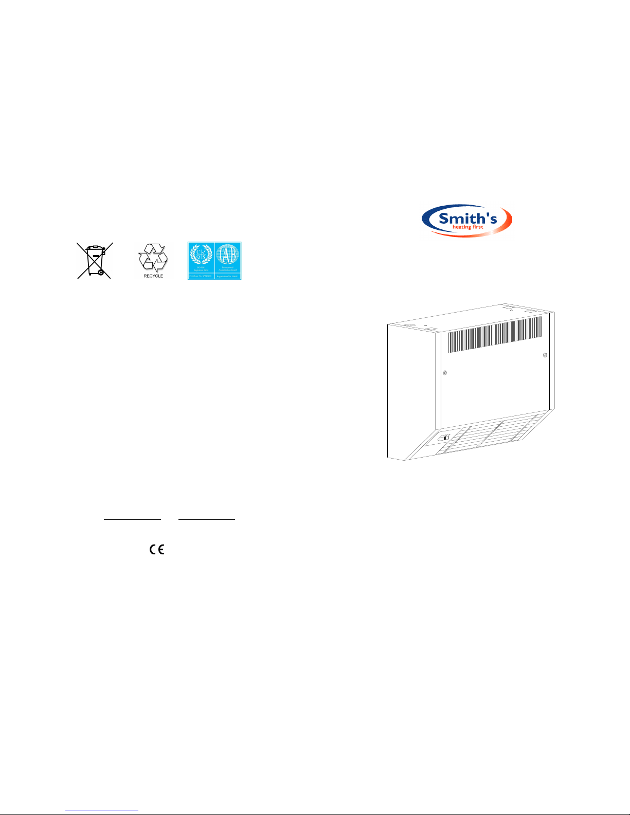
Caspian 60, 90 & 120
High Level Fan Convector
Installation & User Guide
Dear Installer,
Thank you for installing our products, we hope it gives you many years of service;
In the event of items missing or visible damage please contact our After Sales Service
on 01245 324560.
We would be most grateful if you would leave this Installation & User Guide and the
Guarantee Registration Card with the owner.
Thank you for your Co-operation.
Steve Russell
Technical Services Manager
Page 2

Introduction
These heaters are primarily intended for installation directly onto a wall at high level.
They must not be installed in bathrooms or other high humidity areas. Please contact us
on 01245 324900 for details of products suitable for these applications.
These heaters are designed for use on standard two-pipe pumped central heating system
with a maximum water temperature of 86° C and a maximum pressure of 6 bar
(88lbs/in²).
Pipes are 22mm and either pipe may be used as flow or return.
These heaters are classified as a fixed appliances and electrical connection should be via
a 3A fused spur. The fused spur must not be directly below the heater but should be
accessible after completion of the installation. All heaters must be earthed.
We recommend the use of full-flow isolating valves. The valves should be accessible after
completion of the installation. We also advise the fitting of an air vent at the highest point
on either the flow or return pipe to remove any air trapped within the system.
To avoid the possibility of vibration these units must be fitted on a flat even surface.
To conform to Building Regulations Part L (Part J in Scotland), a remote room thermostat
can be used in conjunction with this heater. Refer to the instructions supplied with the
thermostat. For further details please contact our Technical Support on 01245 324560.
Please note the guarantee may be invalidated if this product is not installed
and used in accordance with these instructions.
Installation Guide
1. Remove the front access cover using the supplied keys.
2
How a fan convector works
Fan convectors include an internal water temperature thermostat that prevents the fan
from operating until the central heating system water passing through the heat
exchanger reaches 42°C. This prevents cooler air being circulated at start up.
Heating – see diagram
Ensure your central heating system is ON. Switch on the heater (the neon switch will
illuminate). Set the thermostat control (if fitted) to the desired temperature. Set the heat
output switch to the medium output setting. Providing the water temperature in the
central heating system is more than 42°C and the thermostat (if fitted) is calling for heat
the product will switch on. If you require a faster warm up move the heat output switch
to boost. When the room reaches the desired temperature you may move the heat
output switch to low.
Warning.
This appliance is not intended for use by persons (including children) with reduced physical
knowledge, unless they have been given supervision or instruction concerning use of appliance
by person or persons responsible for their safety. Children should be supervised to ensure that
they do not play with the appliance.
If the supply cord is damaged, it must be replaced by the manufacturer, its service agent or
similarly qualified persons in order to avoid hazard. (Refer EN 60335-1 & EN 60335-2-30
clauses 7.12 & 7.12.5)
Please note in the event of an engineer’s visit, Smith’s Environmental Products Ltd reserve the
rights to apply a call-out charge should the fault prove to be with the system or installation
and not the heater appliance.
7
Hot water from your central heating
system passes through the heat
exchanger transferring its heat to the
aluminium fins. Cooler air is drawn in by
the fan and is heated as it passes over
the heat exchanger beforebeing expelled
gently back into the room. This not only
gives a more even temperature spread
but will heat a room up in less than the
time of a traditional steel panel radiator.
LOW
MEDIUM
BOOST
OFF
ON
Page 3

Fault Finding
1. The fan does not run on any switch setting.
a. Check the power supply is switched ON.
b. Check the fuse in the fused spur.
c. Check the wiring at the fused spur.
2. No heat output.
a. Vent any trapped air from the system (with the heating system turned OFF).
b. Check the central heating is switched ON.
c. If a thermostat is fitted ensure it is calling for heat.
d. Balance the central heating system if installed on the same circuit as panel
radiators and increase the circulating pump speed if required.
e. Increase the boiler water temperature.
In the event of difficulty please contact our technical help-line on 01245 324560. It will
be helpful if you do not disconnect the heater from the central heating system.
Caspian High Level Fan Convector
User Guide
Dear Customer
We are delighted you have chosen our products and trust you are satisfied with the
installation. We would ask you to take a few minutes to read through this User Guide. This will
help you gain the maximum benefit from your heater.
As with all our products your heater is covered by a free five-year parts & labour guarantee
and we would be grateful if you complete and return the Guarantee Registration Card to us as
soon as possible. This will ensure that should you require assistance we can help you quickly
and efficiently.
Thank you for your co-operation.
Steve Russell
Customer Service Manager
01245 324900
Your fan convector is designed to operate as part of your central heating system in the same
way as a panel radiator. Providing you leave the heat output switch in either the low, medium
or boost position it will switch on and off automatically with your central heating system.
6
2. If hanging bracket is used, a distance of 35mm must be left between the top of the
unit and the ceiling.
If the hanging bracket is not used the unit can be mounted up to the ceiling.
3. Fix the product to the wall using appropriate fixings for the wall type. Refer to the
diagram & table below for the fixing-hole positions.
4. Connect the heating system flow and return pipes to the heater pipe work. Do not use
soldered fittings to the heater pipe work as the heat generated may cause damage to
internal wiring and components.
3
A
245
250
294
66
176
140
83
B
I
II
III
530
Model A B
60 595 316
90 895 616
120 1195 2 x 458
140
35
Pipe
Centres
Electrical
supply
either side
Page 4

Note: We recommend the use of full-flow service valves. The valves should be accessible
after completion of the installation. We also advise the fitting of an air vent at the highest
point on either the flow or return pipe to remove any air trapped within the system.
5. Check for water leaks. Remove any trapped air from the unit via the built in bleed
screws as shown in the diagram below.
6. Isolate the electrical supply and connect the heater cable to the fused spur (3 Amp).
The fused spur must not be directly below the heater and must be accessible after the
installation is complete.
4
7. Fit the thermostat if required. There is a connection facility within the heater. Remove the
link and attach wires to terminals 6 & 7 as diagram below.
8.Replace the front access cover, lock and remove key.
9.Please leave this Installation & User Guide with the user for future reference.
Commissioning
1.Turn on the electrical supply at the fused spur.
2. Turn the thermostat control (if fitted) to the maximum.
3. Turn on the central heating system.
4. Turn on the water – see User Guide.
5. If these heaters are installed on the same circuit as panel radiators balance the central
heating system.
6. If the installation is working correctly remember to reset the thermostat control (if fitted) to
its normal setting.
Heat Output Performance
High-Level Model
Heat
Output
(kW)
Heat
Output
(kW
Heat
Output
(kW
High Medium Low
Caspian 60/03 3.4 3.2 2.9
Caspian 60/04 4.6 4.1 3.6
Caspian 90/06 6.7 6.2 5.6
Caspian 90/07 7.8 7.0 6.3
Caspian 120/10 11.4 10.4 8.6
Caspian 120/11 12.2 11.4 9.5
Caspian 120/12 13.1 12.2 10.4
75°C average water temperature, 18°C entering air temperature
It is recommended that these model chosen is capable of maintaining the calculated heat loss
at medium heat output enabling the boost setting to be used for faster heat up and the low
speed for maintaining temperature.
5
Bleed
Valves
TO FAN FROM MAINS
3 Amp
Fused
Spur
 Loading...