

Page 1

EU07955
USER'S GUIDE
VVP-15C ELECTROFISHER
Page 2

I
VVP-15C ELECTROFISHER
www.smith-root.com
Contents
Description ........................................................................ 1
Front Panel Controls ..................................................... 3
Set-up ................................................................................. 5
Begin Electrofishing ...................................................... 5
Basic Hookup ................................................................... 6
Nets .....................................................................................6
Key to Symbols On Labels .........................................6
Possible Overload Conditions ................................... 7
Safety Quick List ............................................................9
Settings Chart .................................................................11
Connector Specifications ...........................................12
Items manufactured by companies other than Smith-Root carry the
original manufacturer’s warranty. Please contact product manufacturer for return instructions.
All Smith-Root, Inc. manufactured products are covered by a one year warranty.
Credit & Refund Policy: Customers returning equipment, in new condition, will be
given credit within five days from the date of the return. A return authorization must
accompany returns. Valid equipment returns include, but are not limited to, ordering incorrect equipment, funding deficits, and defective equipment returned for
reimbursement. All returns are subject to a restocking fee and applicable shipping
charges. The restocking fee is figured at 10% of the purchase price but not less than
$20.00. Customers receiving equipment in damaged condition will be referred to the
shipping company for insurance reimbursement.
Rev. 042705-013
WARNING - Battery posts, terminals and related accessories contain lead compounds, chemicals known to the
State of California to cause cancer and reproductive
harm. Wash hands after handling.
Page 3
1
USER’S GUIDE
2015
DESCRIPTION
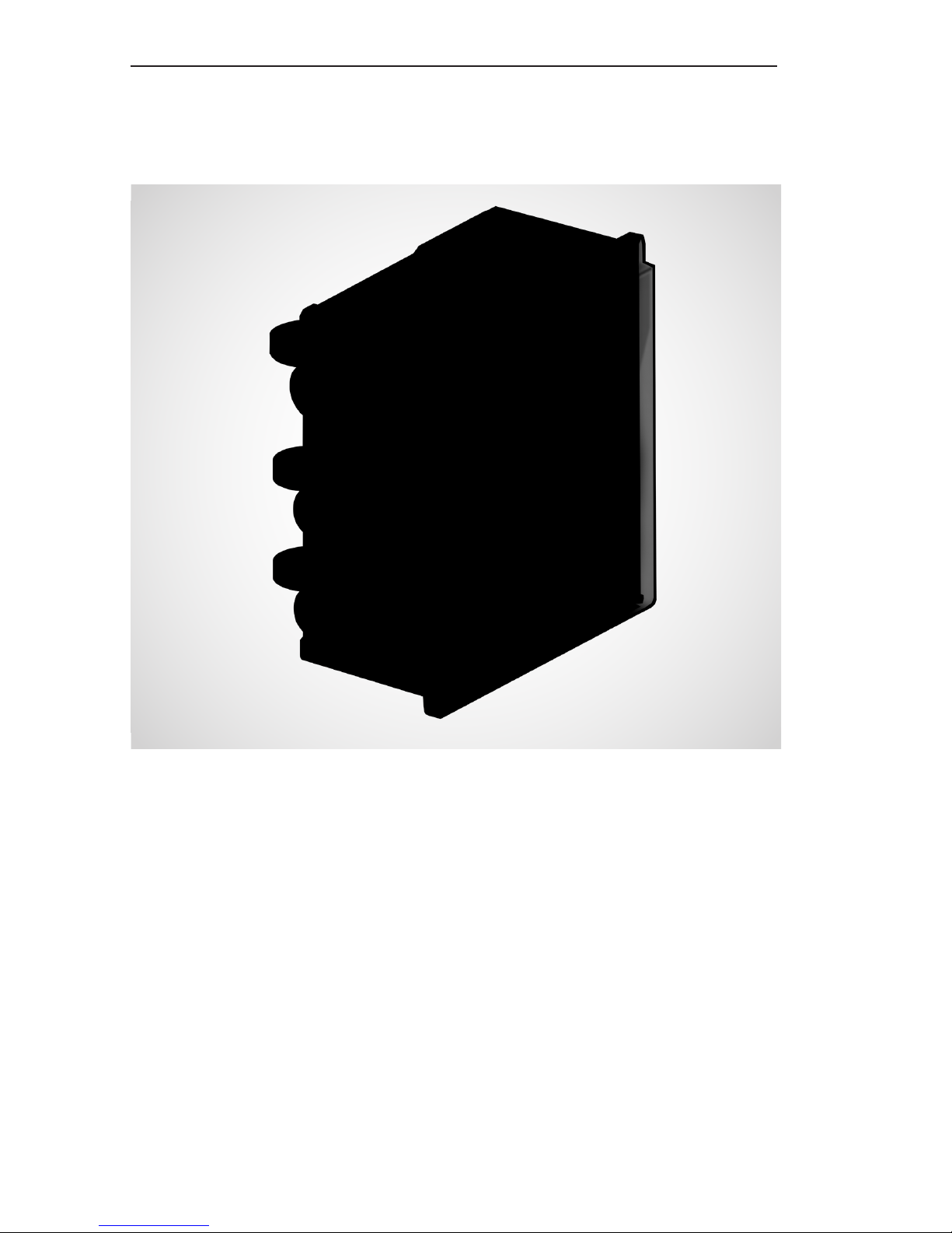
The VARIABLE VOLTAGE PULSATOR ELECTROFISHER MODEL VVP-15C is
designed to supply DC or DC Pulsed voltages for use in electrofishing. Great care
has been taken to improve upon the original designs of the VVP-15 and MK-22.
This updated electrofisher provides almost identical control features and metering to allow consistency with previous samplings. Higher efficiency is an added
benefit of our Generation C, allowing increased samples with less wear and tear
on equipment.
The VVP-15C requires at minimum a 5000 watt generator to reach full rated output.
Generators with less output can be used but will not achieve full output potential.
Recommended Generators: Honda EM5000S, Honda EG5000, Honda EM3800S or
Honda EG3500.
This equipment will not function properly when operated from a 240 Volt AC generator if
the generator neutral line is grounded or connected to any other points. Consult generator
manufacturer for specifications regarding whether your generator has a floating neutral or
procedures to modify your generator. This applies to both the 240Volt and 120V outputs.
Additional caution should be taken to insure that any devices used on the 120V output are not
internally grounded to the neutral. If the neutral connections cannot be removed a 240 volt to
240 volt isolation transformer of adequate wattage rating must be used (5000-Watt Nominal,
SRI line #7791).
Page 4
2
VVP-15C ELECTROFISHER
www.smith-root.com
WARNING!: HIGH VOLTAGE IS USED IN THE OPERATION OF THIS
EQUIPMENT! DEATH ON CONTACT MAY RESULT IF PERSONNEL FAIL TO
OBSERVE SAFETY PRECAUTIONS. BE CAREFUL TO AVOID CONTACT
WITH ALL CIRCUIT COMPONENTS AND CONNECTIONS WHILE CHECKING
OR SERVICING THIS EQUIPMENT
VVP-15C Combo Package Includes:
Description Quantity
Control Box ................................... 1
Foot Switch ...................................1
Input Power Cord ........................ 1
Output Power Cord ....................2
DESCRIPTION
Page 5
3
USER’S GUIDE
2015
1.
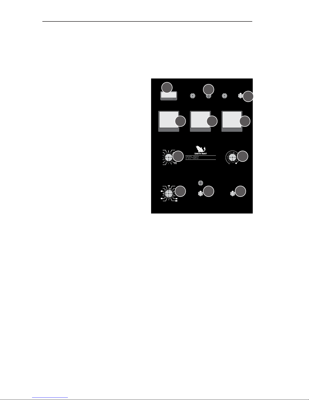
SECONDS: LCD timer. Shows
accumulated electrofishing
time since last reset.
2.
OUTPUT STATUS INDICATORS
(3):
OUTPUT ON: Red indicator
light indicates that the output
from the unit is ON.
OUTPUT OFF: Green indicator
light indicates that the output
from the unit is OFF.
OVERLOAD: Red indicator
light indicates average or peak
output current overload.
3.
ELECTRODE SELECTOR: This
switch selects the active control input(s). In either position,
both anode and both cathode
connectors will be active.
4.
INPUT VOLTAGE AC METER:
Indicates the RMS value of AC
input voltage.
5.
OUTPUT AMPS METER: Indi-
cates output current.
6.
OUTPUT VOLTAGE METER:
Indicates the value of DC output
voltage.
7.
DUTY CYCLE CONTROL: Selects
continuous DC mode, desired
duty cycle of standard DC
Pulses or number of burst pulses
for CPS modes.
8.
VOLTAGE OUTPUT ADJUST
CONTROL: Output voltage
from the Model VVP-15C can be
varied from 0 Volts to Maximum
Volts of selected Range (may be
limited by load conditions and
overload protection) for all out-
FRONT PANEL CONTROLS:
puts—DC, and Pulsed DC (CPS
included).
9.
OUTPUT FREQUENCY CONTROL: selects desired frequency
of DC Pulses.
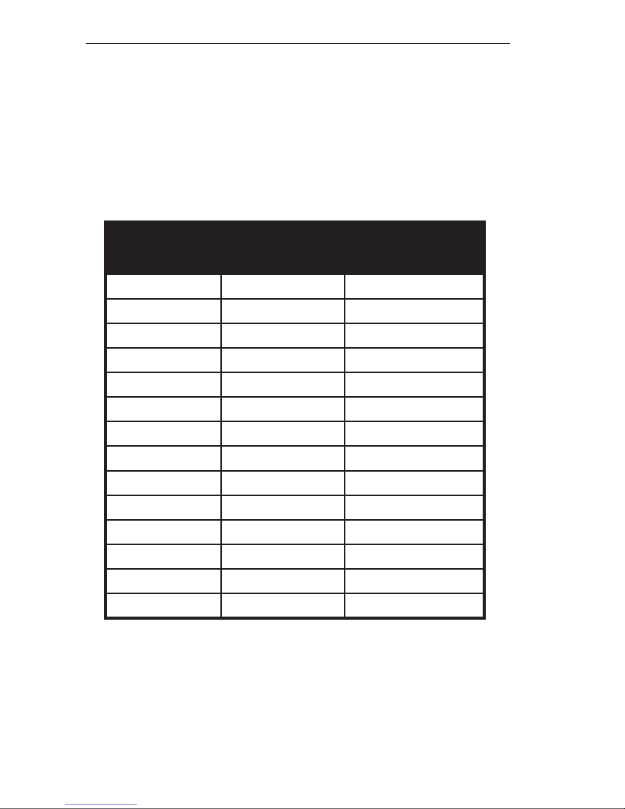
The Pulsed DC output from
the unit is a rectangular pulse
voltage with a possibility of 14
preset duty cycles and 14 preset
frequencies. Each duty cycle can
be used with each frequency.
This allows for 196 standard
pulse mode options with duty
cycles between 10% and 80%
and frequencies between 5 and
120 Hz. The CPS modes have 3
pulses per burst and 6 pulses
per burst options that work in
combination with designated
frequencies (15Hz, 30Hz, 45Hz,
60Hz, 90Hz and 120Hz) for a
SECONDS
INPUT VOLTS AC
DUTY CYCLE
OUTPUT FREQUENCY
ON
600V
300VOFF
VOLTAGE ADJUST
MIN. MAX.
OUTPUT AMPS OUTPUT VOLTS
OVERLOAD ANODE 1
ANODE 1 & 2
OUTPUT ON OUTPUT OFF
www.smith-root.com
Vancouver, Washington, USA
VARIABLE VOLTAGE PULSATOR
VVP-15
C
ELECTROFISHER
50
55
45
10
60
40
20
70
35
25
15
5
80
90
120
30
CPS
3 PULSE
50
55
10
60
45
40
20
70
35
25
OFF CONT. DC
80
30
4
1
2
3
5 6
7 8
9
10 11
Page 6
4
VVP-15C ELECTROFISHER
www.smith-root.com
total of 12 CPS modes. These
configurations allow for a total
of 208 accurate and repeatable DC Pulse modes. The DC
continuous mode is not affected
by the position of the frequency
control.
10.
OFF/ON: Is the main power
switch and circuit breaker. The
green LED indicates input power
to the unit.
11.
OUTPUT RANGE SELECT:
Switch selects either 300 or 600
as maximum output voltage.
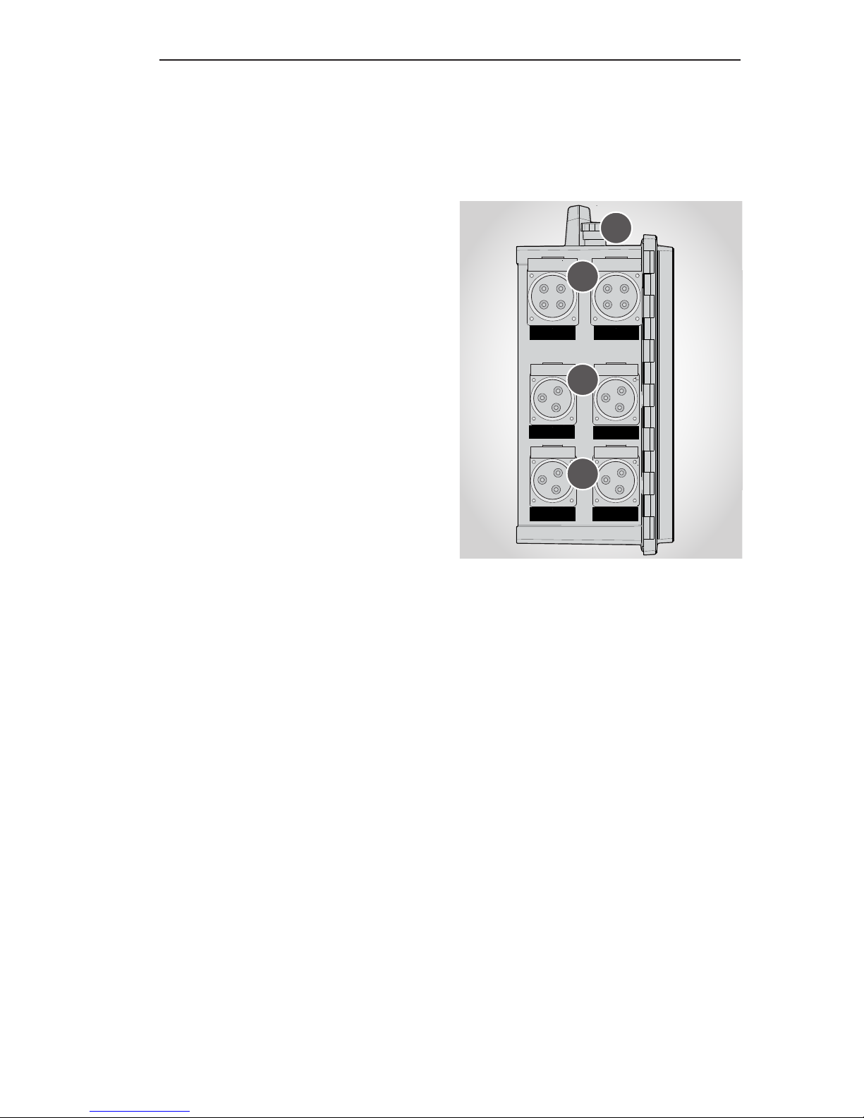
TOP BUTTON - SIDE
ELECTRODE/CONTROL
CONNECTORS:
12.
EMERGENCY STOP: Switch
disables the electrofisher. For
additional safety also move the
input circuit breaker to the off
position, turn off the generator
and after the generator stops
disconnect the power cord from
the generator.
13.
CONTROL 1/CONTROL 2: These
connectors are for foot switch or
hand switch control inputs.
14.
ANODE 1/ANODE 2 OUTPUT:
These connectors are the positive + electrode connections.
15.
CATHODE 1/CATHODE 2: These
connectors are the negative –
electrode connections.
CONTROL 1 CONTROL 2
CATHODE 1 CATHODE 2
ANODE 1
ANODE 2
13
12
14
15
CONTROLS
Page 7
5
USER’S GUIDE
2015
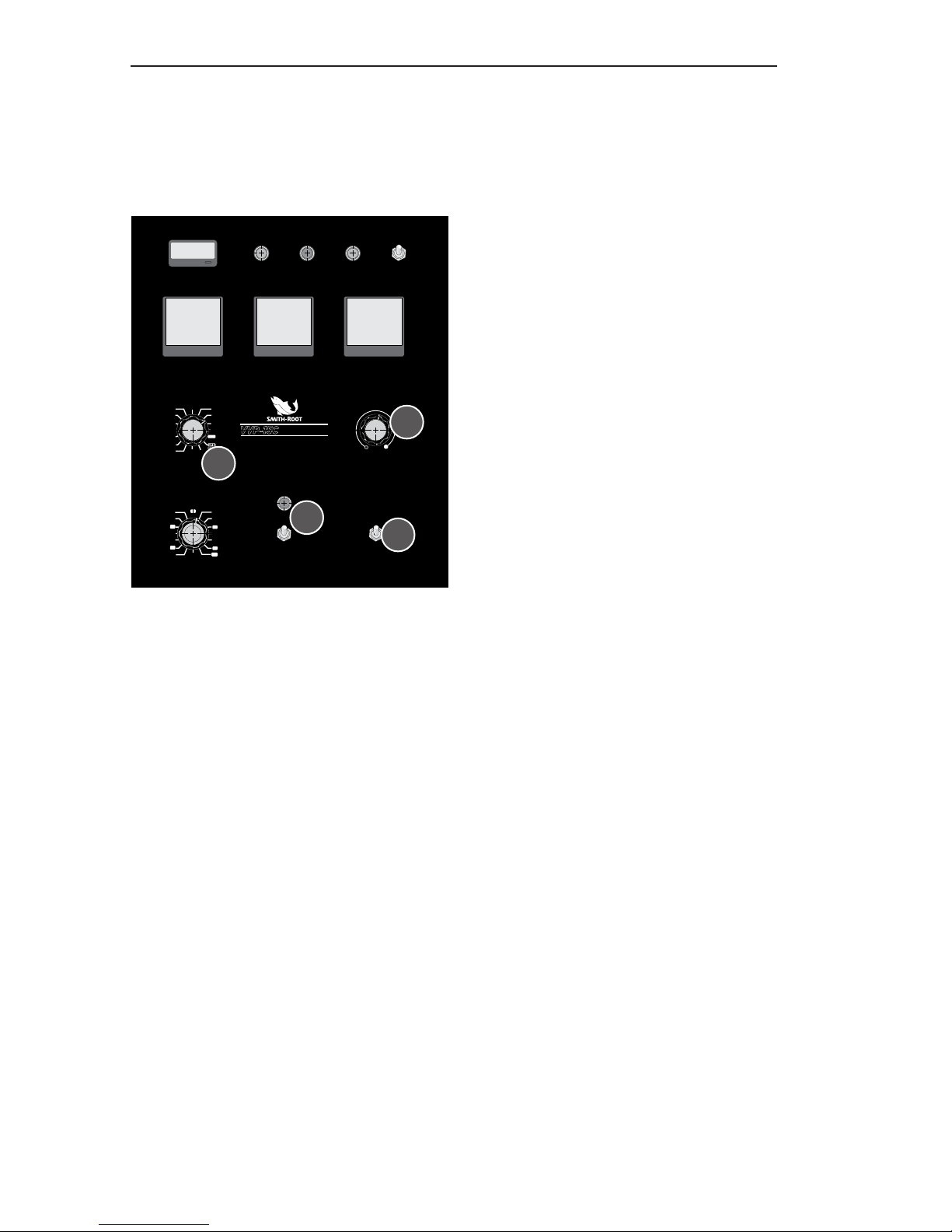
1. Set the POWER switch to
the OFF or down position
(Fig. 1, 1).
2. Set the OUTPUT VOLTAGE
ADJUST control to the
extreme counter-clockwise
position (Labeled MIN.)(Fig.
1, 2).
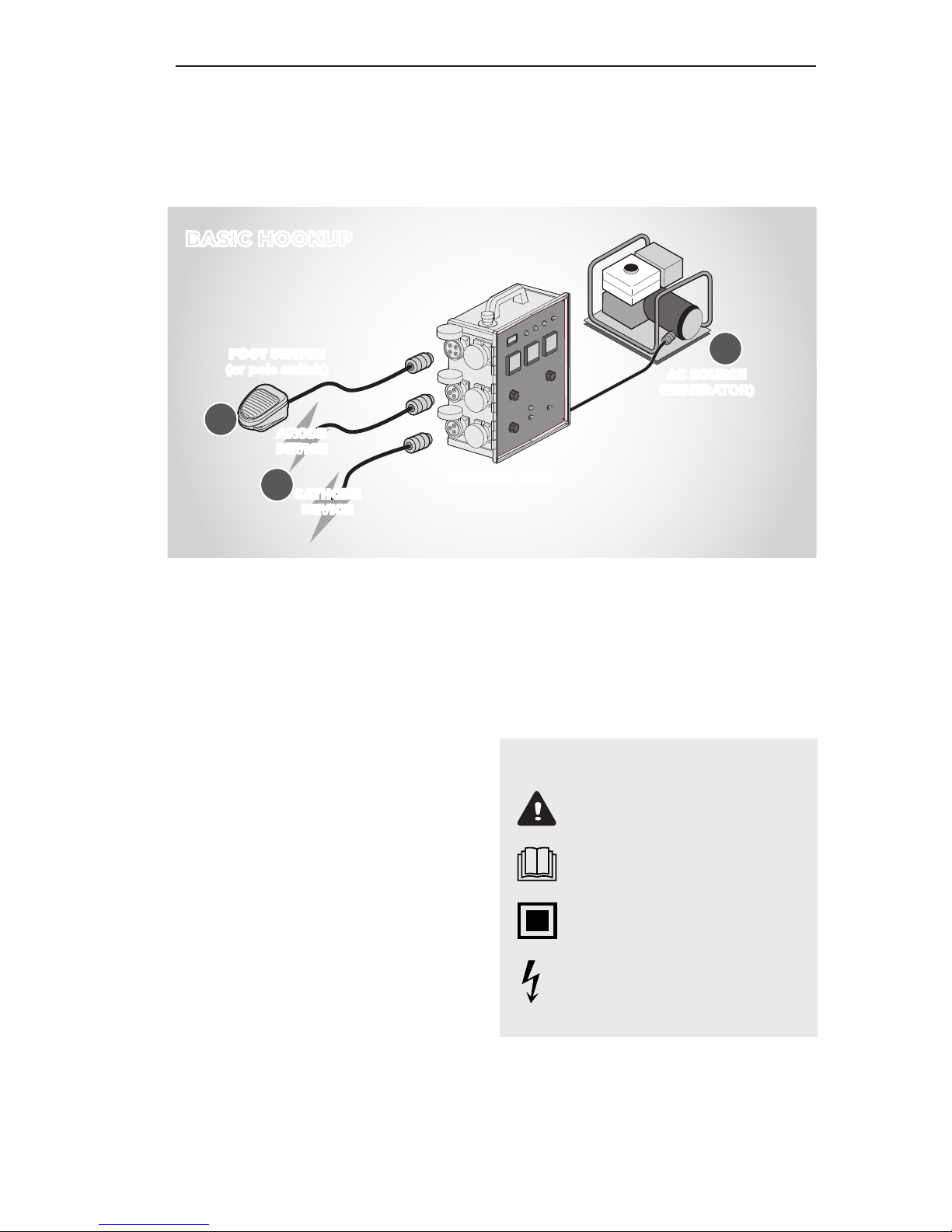
3. Attach foot switch (or other
control device) (Fig. 2, 3).
4. Connect the electrodes
to be used to the desired
output connector (Fig. 2, 4).
5. Connect the AC INPUT 230
VAC connector to the AC
power source (generator)
(Fig. 2, 5).
6. Set the OUTPUT (range)
switch to the desired position (Fig. 1, 6).
SET-UP INSTRUCTIONS
7. Select desired DUTY CYCLE
& FREQUENCY, (Cont. DC or
pulsed DC are selected at this
step) (Fig. 1, 7).
BEGIN ELECTROFISHING
1. Start the generator.
2. Toggle power circuit
breaker ON.
3. Put the Emergency Stop
switch in the on position.
4. Depress foot switch or
anode pole thumb switch.
5. Increase output by rotating
OUTPUT ADJUST CONTROL in a clockwise movement.
6. During operation, before
changing OUTPUT (range)
switch, set the OUTPUT
ADJUST control to the
extreme counter- clockwise
position (MIN.) and release
footswitch(s)/pole switch(s)
7. Make sure that the front
cover is closed during
actual electrofishing operations and keep the front
panel safe from splashes
and rainy weather.
SECONDS
INPUT VOLTS AC
DUTY CYCLE
OUTPUT FREQUENCY
ON
600V
300VOFF
VOLTAGE ADJUST
MIN. MAX.
OUTPUT AMPS OUTPUT VOLTS
OVERLOAD ANODE 1
ANODE 1 & 2
OUTPUT ON OUTPUT OFF
www.smith-root.com
Vancouver, Washington, USA
VARIABLE VOLTAGE PULSATOR
VVP-15
C
ELECTROFISHER
50
55
45
10
60
40
20
70
35
25
15
5
80
90
120
30
CPS
3 PULSE
50
55
10
60
45
40
20
70
35
25
OFF CONT. DC
80
30
2
6
7
1
Fig. 1
Page 8
6
VVP-15C ELECTROFISHER
www.smith-root.com
AC SOURCE
(GENERATOR)
CONTROL UNIT
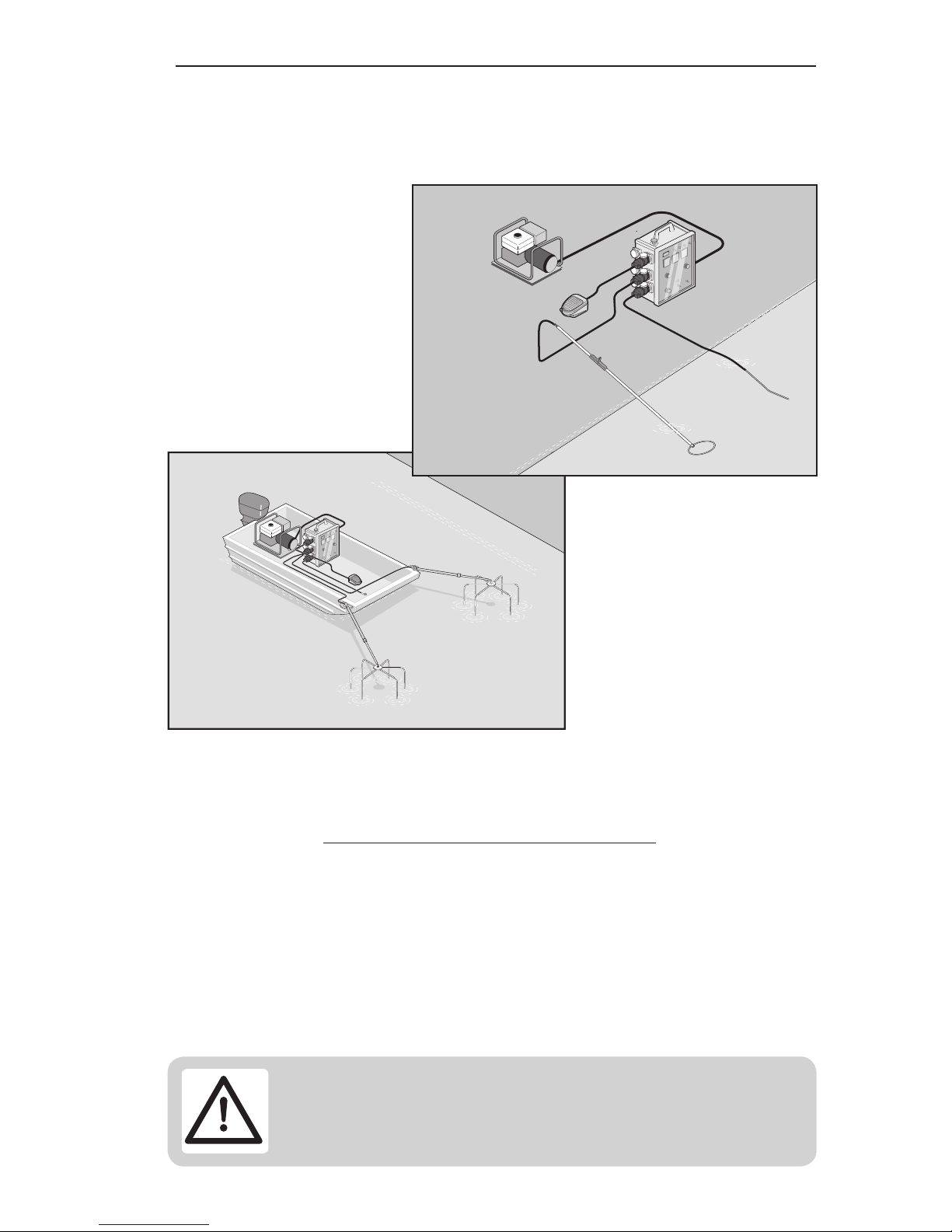
BASIC HOOKUP
FOOT SWITCH
(or pole switch)
ANODE
DEVICE
CATHODE
DEVICE
NETS
No net of any kind shall be
attached to any electrode.
Nets used with this equipment
shall have the following characteristics:
• The handle shall be con-
structed of a non-conductive
material.
• The handle shall be of suf-
ficient length to avoid hand
contact with the water.
• The handle shall not be
wrapped or covered metallic
material.
KEY TO SYMBOLS ON LABELS
- Danger/Important
- Read The Manual
- Double Insulated
- High Voltage
• The net shall not have a
metallic weighting chain
extending beyond the bottom
edge of the net proper.
3
4
5
Fig. 2
SET-UP
Page 9

7
USER’S GUIDE
2015
POSSIBLE OVERLOAD CONDITIONS DURING OPERATION
1. AVERAGE OVERLOAD - Overload lamp turns on (continuous)
Cause:
Average power has exceeded programmed
limits.
Characteristics:
During operation “OUTPUT ON” indicator
will turn off and “OUTPUT OFF” indicator will
turn on. The output will be disabled. Operator
will observe decreased output voltage and
current. This condition will automatically reset
after three seconds. The three second time
out can not be bypassed.
Correction:
If average overload occurs repeatedly the
operator must reduce the output voltage and/
or one of the mode settings.
2. PEAK OVERLOAD - Overload lamp flashes - (this condition
should not occur frequently).
Cause:
Likely shorted output, possible extreme loading conditions.
Characteristics:
“OUTPUT ON” indicator will turn off and
“OUTPUT OFF” indicator will turn on. Output
will be disabled. VVP-15C will not reset after
three seconds.
Turn off control circuit (foot switch or anode
pole switch).
Page 10

8
VVP-15C ELECTROFISHER
www.smith-root.com
Correction:
Turn off the “ON/OFF” circuit breaker. Return
VVP-15C to set-up conditions. Inspect electrodes to ensure output is not shorted. If situation occurs at low settings then perform
detailed inspection of output cabling and
arrays. If unable to correct, call Smith-Root,
Inc. for assistance.
If green ‘ON’ indicator light isn’t lit, check
input circuit breaker and generator overload
indicator.
3. GENERATOR OVERLOAD
Cause:
Generator power rating has been exceeded.
Characteristics:
“OUTPUT ON” indicator and “OUTPUT OFF”
indicator will flash alternately. Output will
be disabled. VVP-15C will reset when safety
switch is released.
Correction:
If generator overload occurs repeatedly the
operator must reduce the voltage output and/
or one of the mode settings. If a generator
with an output rating of less than 5000 watts
is being used a larger generator may be necessary.
OVERLOAD
ANODE 1
ANODE 1 & 2
OUTPUT ON OUTPUT OFF
OVERLOAD
Page 11

9
USER’S GUIDE
2015
1. At least one member of the
crew must have current first
aid and CPR cards.
2. Make sure every member of
your crew knows where the
nearest hospital is and how
to get there or where to go
to get help.
3. All members of the crew
should have completed an
electrofishing course.
4. Before loading up equipment and heading into
the field make sure every
member of the crew knows
your evacuation routes in
case of an accident.
5. Check the equipment for
damaged or missing parts
and for proper operation.
Never use an electrofisher
that is in poor condition or
not working correctly as it
can present a severe shock
hazard.
6. Check the cathode cable
for wear and burrs that may
cause injury or tear holes in
protective clothing. Check
the insulation for damage.
Replace the cathode as
necessary.
7. Check the anode pole for
cracks in the fiberglass and
handle assembly. Replace
as necessary.
8. Check the curl cord for
cracks and abrasion. Do not
use a cracked pole or a pole
with a damaged curl cord.
9. Check your boots and high
voltage gloves for holes.
Boots and gloves must be
water tight and without any
holes. Repair or replace as
necessary.
10. If you are using chest
waders you should use a
wading belt. A wading belt
will slow the entry of water
into the waders.
11. Use only dip nets with
non-conductive handles.
Never use an anode as a
net, as it is extremely dangerous to other members
of the crew and can cause
severe injury to any fish
caught with it.
12. Never electrofish alone.
13. Never electrofish when you
are tired.
14. Only one person on a crew
can order the power for the
electrofisher to be turned
on, and that person is the
crew leader. The crew
leader is responsible for the
safety of everyone on the
crew.
SAFETY QUICK LIST
Page 12

10
VVP-15C ELECTROFISHER
www.smith-root.com
15. Any member of the crew
can call for or turn off the
power to the electrofisher.
16. If an accident occurs, stop
electrofishing and turn off
the power to the VVP-15C.
The remaining members
of the crew should help
or attend to the accident
victim. Get help for the
injured person if necessary.
Evaluate what happened
and make the necessary
procedural or equipment
changes before proceeding.
17. Never electrofish with
spectators on shore. Electric fields can travel large
distances through buried
pipes, metal culverts, and
metal sheet piling. If spectators show up during electrofishing, stop the operation and go explain what
you are doing. Explain the
risks to them being there
and ask them to please
leave for their own safety.
If they refuse to leave, stop
electrofishing, load your
equipment, and leave the
area.
WARNING: Operating this
equipment in a manner not
specified in this manual
or with accessories not
approved by Smith-Root, Inc.
may impair the protection
offered by the equipment.
SAFETY
Page 13
11
USER’S GUIDE
2015
VVP-15C SETTINGS
FREQUENCY DUTY CYCLE OUTPUT SELECT
15 CPS 3 PULSE 300 OR 600
30 CPS 3 PULSE 300 OR 600
45 CPS 3 PULSE 300 OR 600
60 CPS 3 PULSE 300 OR 600
90 CPS 3 PULSE 300 OR 600
120 CPS 3 PULSE 300 OR 600
15 CPS 6 PULSE 300 OR 600
30 CPS 6 PULSE 300 OR 600
45 CPS 6 PULSE 300 OR 600
60 CPS 6 PULSE 300 OR 600
90 CPS 6 PULSE 300 OR 600
120 CPS 6 PULSE 300 OR 600
N/A CONT. DC 300 OR 600
5 THRU 120 10 THRU 80 300 OR 600
VVP-15C SETTINGS CHART
Page 14

12
VVP-15C ELECTROFISHER
www.smith-root.com
CONNECTOR SPECIFICATIONS
CONNECTORS ON SIDE OF VVP-15C ELECTROFISHER:
• Anode: Cee Norm 1357
• Control: Cee Norm 13455
• Cathode: Cee Norm 1356
CONNECTORS ON CABLES FOR VVP-15C ELECTROFISHER:
• Input Power: Cee Norm 21250
• Anode: Cee Norm 21238
• Control: Cee Norm 21891
• Cathode Cee Norm 21237
CONNECTORS ON GENERATORS OR PARALLELING BOX:
• Cee Norm 1360
SPECIFICATIONS
Page 15

[email protected]
(360) 573-0202
14014 NE Salmon Creek Ave.
Vancouver, WA 98686
www.smith-root.com
S
i
n
c
e
1
9
6
4
 Loading...