

Page 1
07289.03 1601 Fish Counter.indd
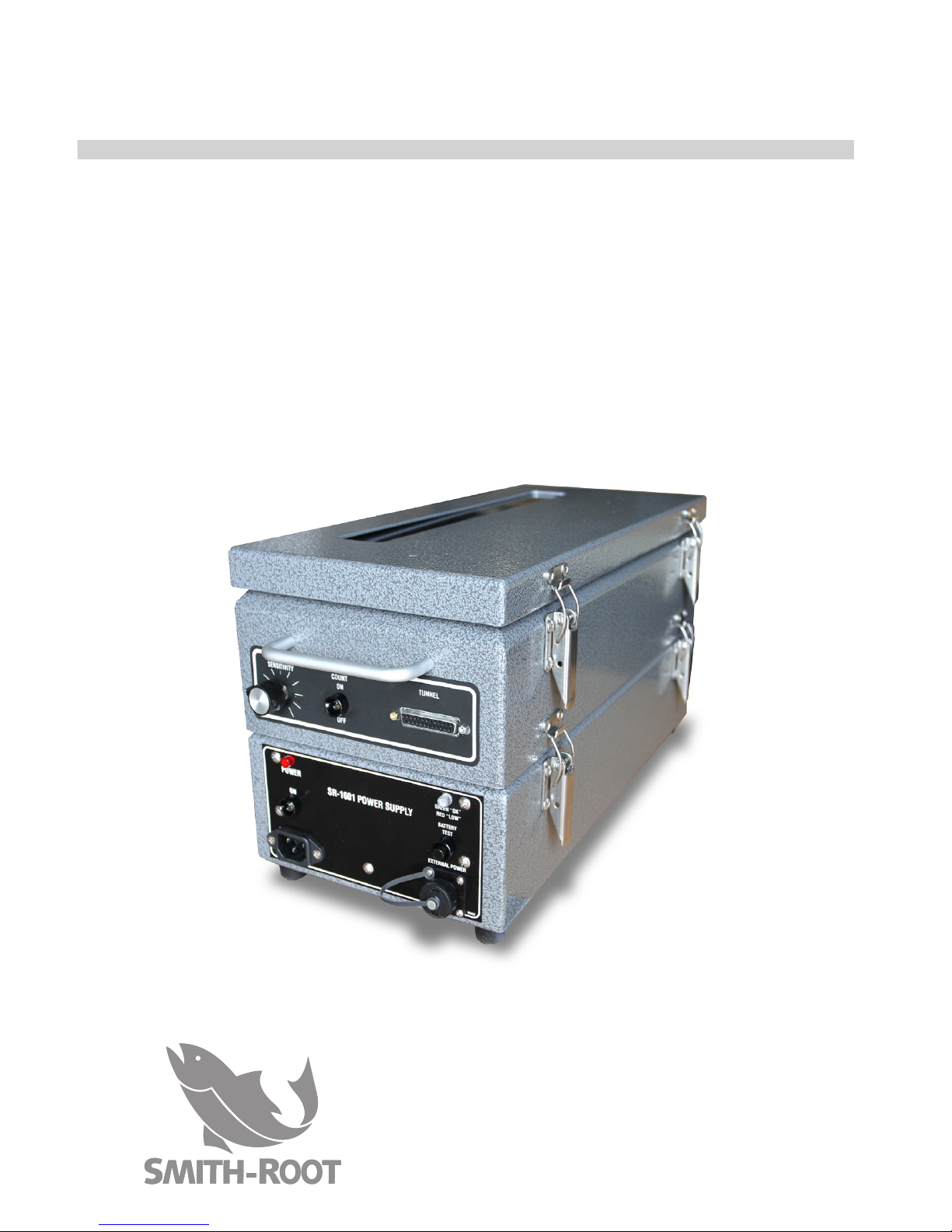
USER'S GUIDE
1601 FISH COUNTER
Page 2

Page 3

Items manufactured by companies other than Smith-Root carry
the original manufacturer’s warranty. Please contact product
manufacturer for return instructions.
All Smith-Root, Inc. manufactured products are covered by a one year warranty.
Credit & Refund Policy: Customers returning equipment, in new condition, will
be given credit five days from the date of the return. A return authorization
must accompany returns. Valid equipment returns include, but are not limited
to, ordering incorrect equipment, funding deficits, and defective equipment
returned for reimbursement. All returns are subject to a restocking fee and
applicable shipping charges. The restocking fee is figured at 10% of the
purchase price but not less than $20.00. Customers receiving equipment in
damaged condition will be referred to the shipping company for insurance
reimbursement.
07289.03 1601 Fish Counter.indd - © 2017 Smith-Root, Inc.
www.smith-root.com
CONTENTS
INTRODUCTION ..........................................................4
FEATURES ..................................................................... 5
TYPES OF TUNNELS ................................................. 7
TJB-16 JUNCTION BOX ............................................. 7
POWER REQUIREMENTS ........................................8
CHANGING DISPLAY BATTERIES ........................ 8
CONNECTORS AND PLUGS ...................................9
CONTROLS AND INDICATORS ........................... 10
OPERATION .................................................................12
IN CASE OF DIFFICULTY ........................................13
SPECIFICATIONS ...................................................... 14
Page 4
4
USER’S GUIDE
2017
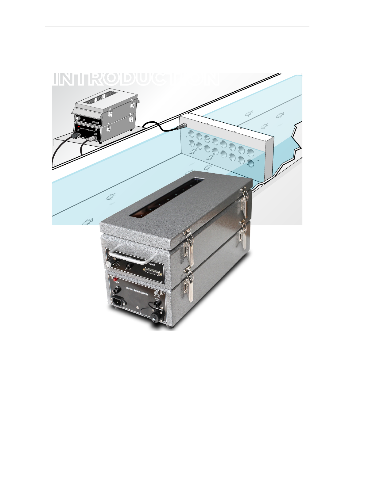
The SR-1601 Fish Counter is a 16-channel fish
counter, integrating 16 individual counters into one unit.
This unit is designed for hatchery fry, migrating smolt,
fish eggs, emergent shrimp, and other macro organisms. The SR-1601 simultaneously monitors all 16 tunnels
for downstream movements, giving individual counts
for each tunnel. In order to be counted, macro organisms pass through one of multiple counting tunnels and
are tallied on separate 16-digit displays. The system
easily tallies 10 counts per second per channel, giving
576,000 counts per hour.
INTRODUCTION
Page 5
5
SR-1601 FISH COUNTER
www.smith-root.com
GENERAL DESCRIPTION
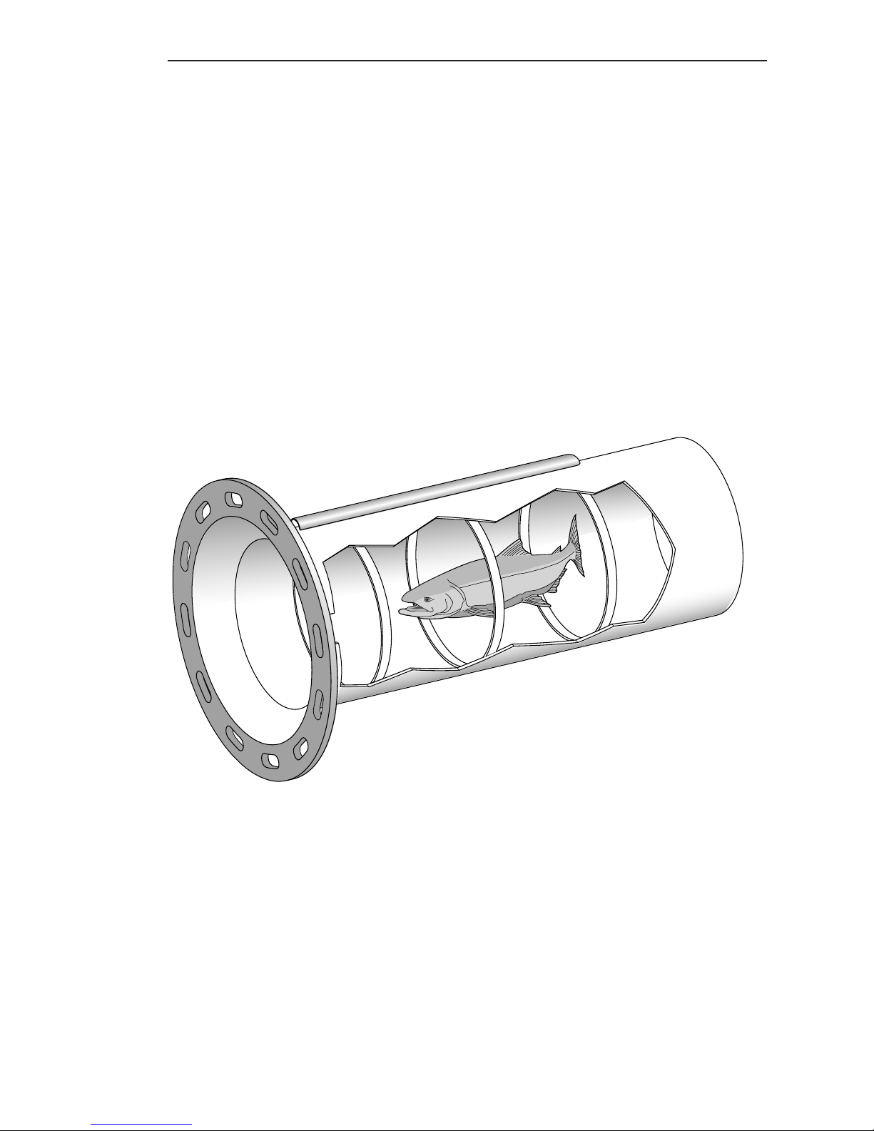
The Model SR-1601 Fish Counter features a balanced resistance bridge circuit using the tunnel elements to count fish
in fresh water. Electronic counters simultaneously monitor
up to 16 tubes for downstream fish movements, giving a
“real time” readout for each tube showing count distribution.
The counting heads are interchangeable and are available
with tube diameters ranging from 1/2 to 3 inches. Larger tunnels are available on a custom order basis.
PRINCIPLE OF OPERATION
Operation of the SR-1601 Counter is based on the “Balanced
Resistance Bridge Principle” using water in the count head
as two elements of a four element Balanced Bridge. Passage
of a fish through one of the tubes of the count head causes
corresponding changes in that tube’s conductance. These
conductance changes are used by the SR-1601 to sense the
presence of fish in the tubes of the counting head.
Page 6
6
USER’S GUIDE
2017
ADVANCED FEATURES
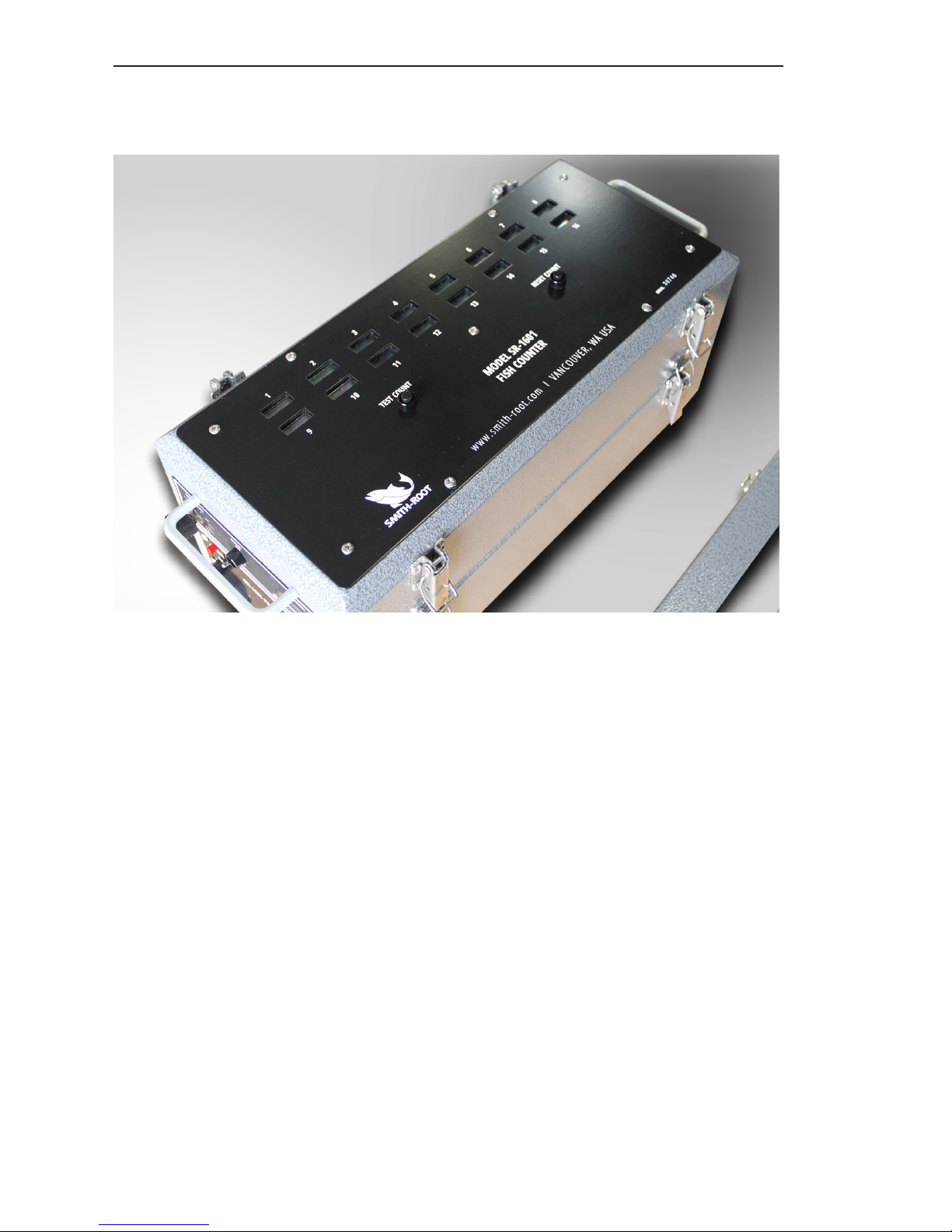
The SR-1601 employs numerous advanced features providing such functions as to simultaneously monitor 16 different
tunnels giving real time distribution of counts. The counts
are displayed on liquid crystal displays (LCDs) which provide
easy readability even in direct sunlight. The count is retained
by internal display batteries if power to the fish counter is
lost. Also included is a wide-range sensitivity control which
provides the ability to set the size of the smallest fish that
will be counted.
WATER CONDITIONS
The counter is designed to work in fresh water with a conductivity of 10 to 500 microsiemen. The 16 tube counting
head must be completely submerged in fresh water and an
appropriate water head developed to overcome the swimming ability of the fish to be counted. The fish are then
crowded into the vicinity of the tube entrances where they
are pulled through and counted. With proper tube size and
water flow, count accuracy is better than 98%.
Page 7
7
SR-1601 FISH COUNTER
www.smith-root.com
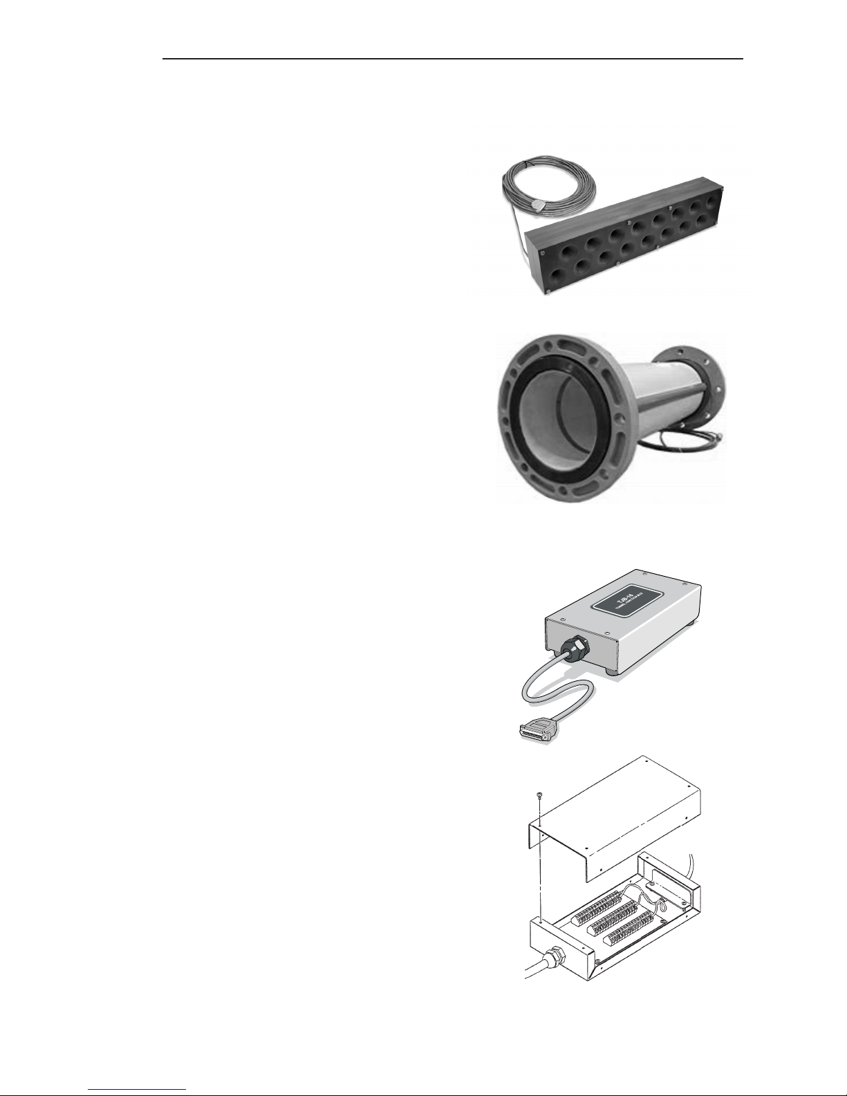
COUNTING HEAD
The SR-16-CH Counting Head
is a single unit containing 16
separate counting tubes. Each
tube in the Counting Head has
a smooth tapered entrance to
prevent abrasive damage to the
fish. The tubes may have diameters ranging from 1/2 to 3 inches. Tubes are usually arranged in
two rows of 8 tubes each. For
the best accuracy, tube diameter should be no more than half
of the length of the fish to be
counted.
SINGLE TUNNEL
For most fish counting operations, individual tunnels are
connected to the 1601 via the
TJB-16 Junction Box, which
in turn is connected to the 25
pin connecter on the panel of
the counter. Up to 16 individual
tunnels can be connected in this
manner.
TJB-16 JUNCTION BOX
Allows the connection of up
to sixteen individual tunnels to
the 1601 Fish Counter. Signal
cables pass through a strain-relief and connected to screw
terminals on an isolated strip,
which is connected to a 25 pin
female plug that corresponds to
the 1601’s Tunnel plug. Unit is
housed in a waterproof enclosure.
Top to bottom: Counting head; single
tunnel; TJB-16 Junction Box; TBJ-16
terminal connections.
Page 8
8
USER’S GUIDE
2017
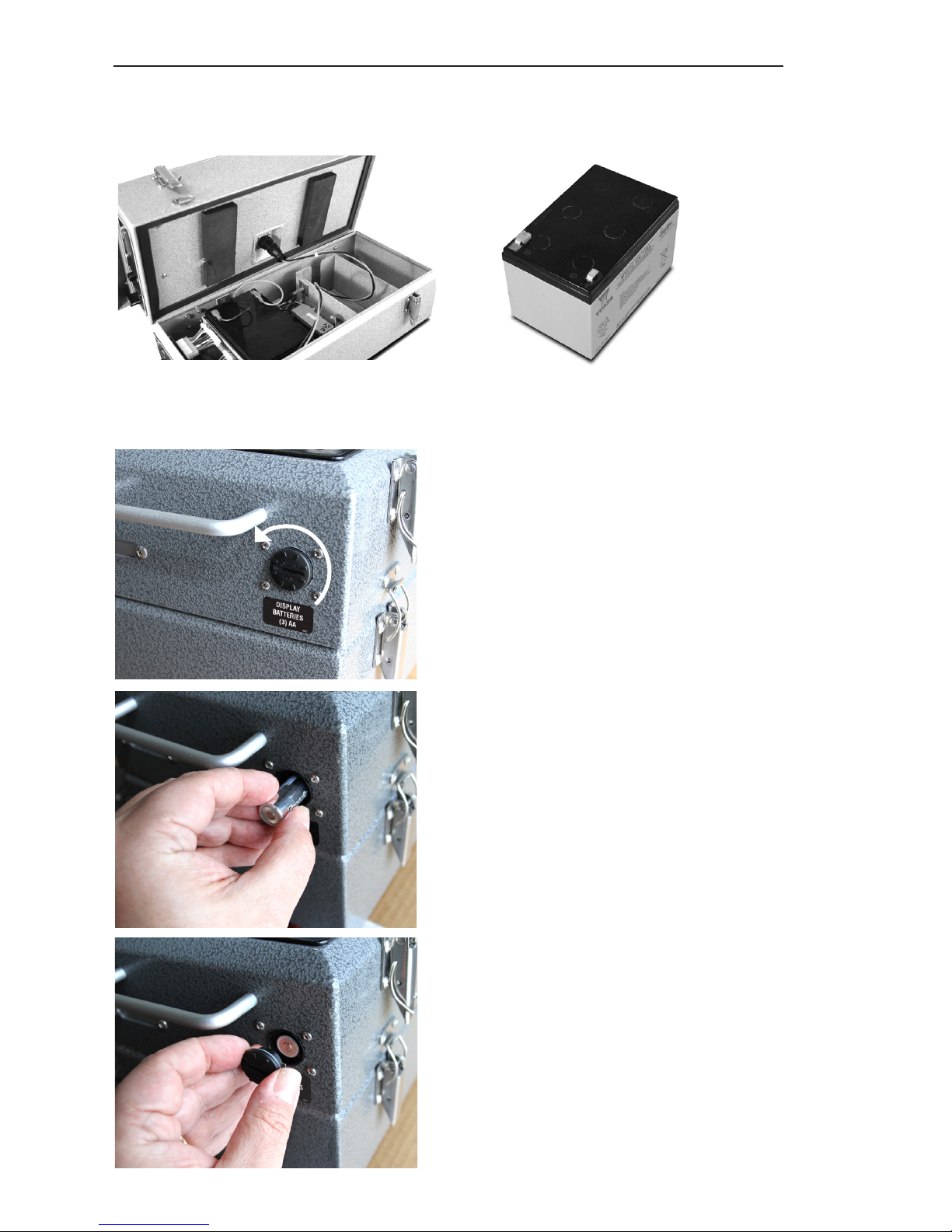
SR-1601 Battery
SR-1601 battery compartment
The Model SR-1601 can be
powered from 115VAC, 60Hz,
from an optional 12 Volt internal battery, or from an optional
12 Volt external battery. Battery life is four days with the
internal 12V batteries. A battery test button is provided
to determine the proper time
for battery change. (3) AA
batteries are provided to preserve count data during power
failure and while changing the
main battery.
CHANGING THE DISPLAY
BATTERIES
To replace the display batteries,
use a screwdriver (or thin coin,
etc.) to turn the cap one-quarter turn counterclockwise and
pull the cap free (1). Slide the
old batteries out and insert 3
new batteries (2), observing
the “+” end towards the cap
(3). To retain counts while
replacing the display batteries,
ensure that the unit is powered
by the AC cord or 12VDC power.
POWER REQUIREMENTS
1
2
3
Page 9
9
SR-1601 FISH COUNTER
www.smith-root.com
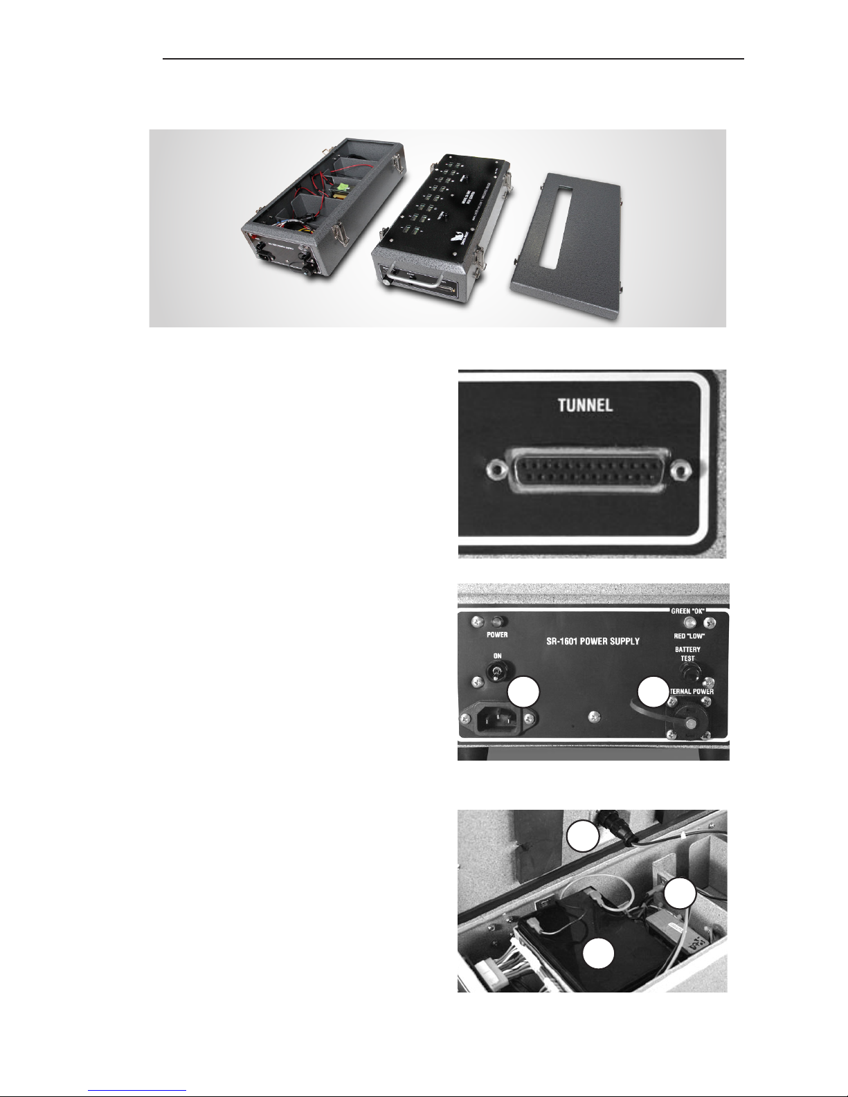
The tunnel connector is a 25
pin data connector with screw
locks.
The lower section of the 1601
houses the AC power supply, connector and optional
batteries. 12 Volt DC power
to the SR-1601 is provided
through a single multi-pin
quick twist positive locking
polarized connector. This insures easy and positive connections.
AC power is plugged in via a
standard AC cord. Up to two
optional 12VDC batteries can
be housed in the lower battery compartment and connected via spade connectors,
which goes to the 4-pin plug
on the bottom of the counter unit. A similar 4-pin plug
is also on the front panel to
allow the connection of an additional 12VDC power source.
Tunnel connector
Power connectors: AC Connector (A);
12V Connector (B)
Internal power connectors: 12V
Connector (C); Spade Connectors (D);
12V Battery (E)
A
C
D
E
B
SR-1601 with lid, battery compartment removed
CONNECTORS AND PLUGS
Page 10
10
USER’S GUIDE
2017
CONTROLS AND INDICATORS
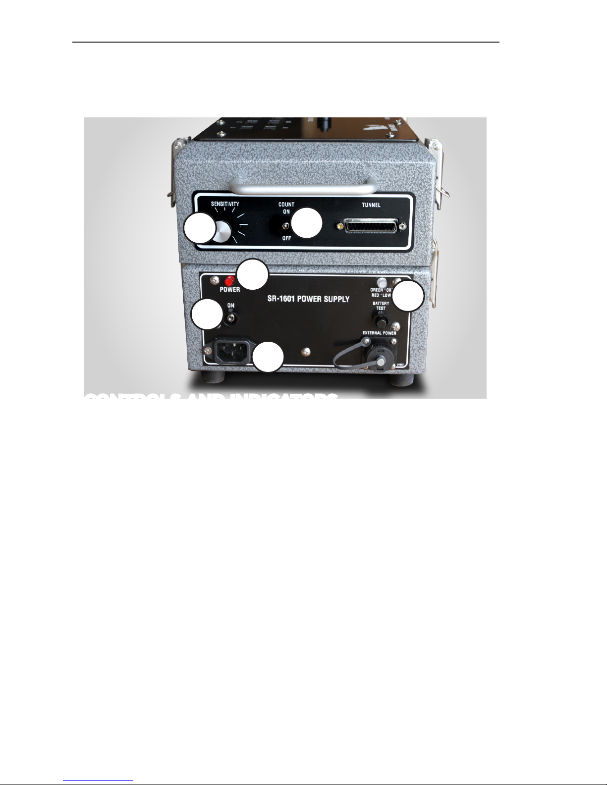
1. Power Switch - Controls the DC power to operate the
fish counter electronics. The DC may be supplied from
the internal battery, from an external 12 Volt DC source,
or from the internal AC powered DC supply. This switch
does not control the AC power to the battery charger
circuit. The battery charger charges the internal 12V
batteries only.
2. Battery Test Switch And Indicator - Press and hold
the switch for 30 seconds. If the indicator stays green
during this time, the battery is OK. If the indicator turns
red or stays red during this time, the battery needs
to be recharged. The internal battery will run the fish
counter for 4 days, depending on water conductivity.
3. Sensitivity - The sensitivity control allows the user to
set the size of the smallest fish that the fish counter will
sense. Turning the control clockwise allows smaller fish
to be detected.
4. Count Switch - When in the OFF position, all inputs to
the counter are disabled. This prevents the accumu-
1
2
3
4
5
5
Page 11
11
SR-1601 FISH COUNTER
www.smith-root.com
lation of any erroneous counts while moving the count
head from rearing pond to rearing pond. For normal
operation, the switch should be in the ON position.
5. AC Power Connector and Indicator Lamp- Lights up
whenever the fish counter is connected to 120VAC, 60
Hz outlet.
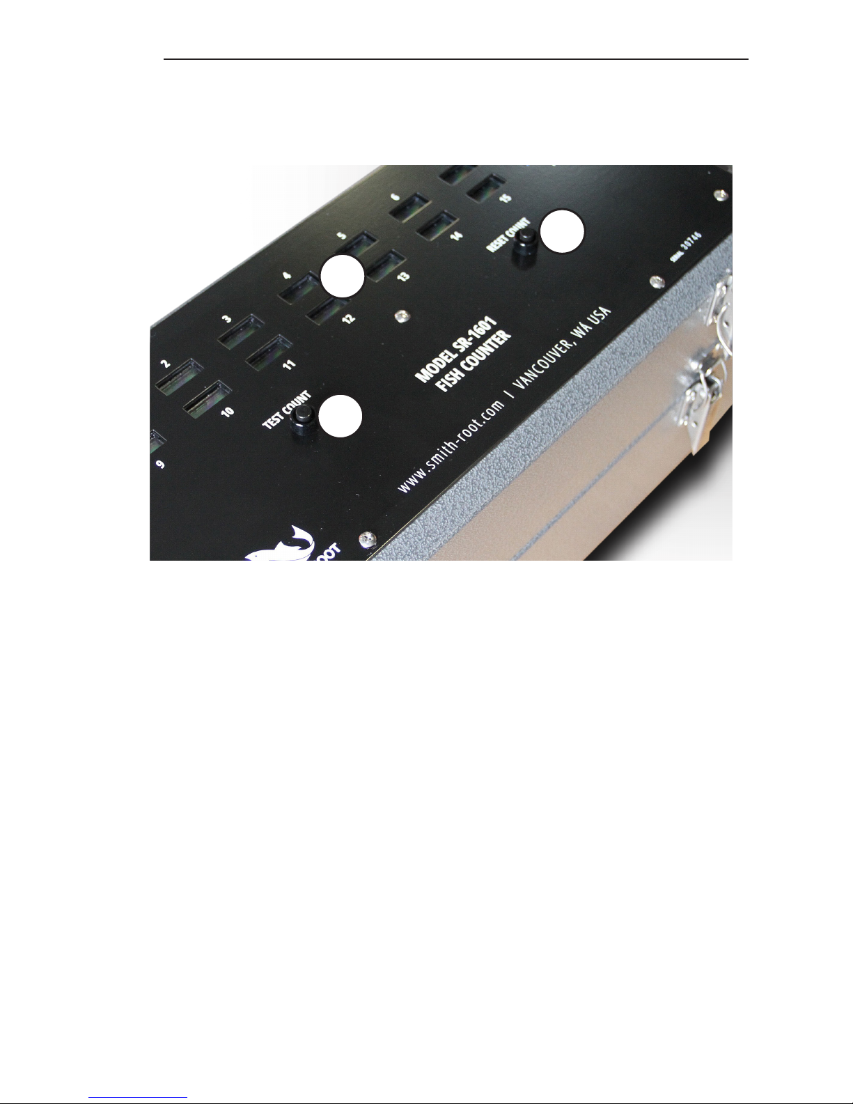
6. Count Test - The switch is used to test the general
functioning of the SR-1601. With the Power and Count
switches ON and count head connected, pressing this
switch causes a single count to be registered on each
display. Counter must be connected to a properly submerged tunnel to properly test count.
7. Count Reset- Resets all the displays to zero.
8. Count Displays - The SR-1601 has 16 individual dis-
plays, one for each counter tube. They are 6-digit LCD
displays which means they can be read even in direct
sunlight. The 16 displays give a real time distribution of
counts for each tube in the count head.
6
7
8
Page 12

12
USER’S GUIDE
2017
OPERATION
1. Submerge the count head in water making sure that all
of the tubes are completely filled with water. Locking
screws must be locked to nuts on counter.
2. Turn the Power Switch ON. It is normal for one or
two counts to appear on the displays when the power
switch is turned on and off.
3. Press the Battery Test switch and check the condition
of the battery.
4. Turn the Count Switch ON.
5. Allow a few fish to pass through the count head and
adjust the sensitivity control clockwise until the counter reliably counts fish as they pass through the tubes.
Turn the sensitivity control up one more mark.
6. Count accuracy may be checked by hand-counting the
fish that are passed through the count head. When you
are satisfied that the sensitivity control is set correctly,
reset the displays and begin counting fish.
Note: The water flow through the count head can have a
dramatic affect on the accuracy of the fish counter. The
hydraulics must be such that the fish cannot resist the
pull of the water as it passes through the tubes. Tube size
is also important and must be such that only one fish at
a time can pass through a particular tube. Fish may go
through different tubes at the same time without any error
occurring. Air bubbles and debris passing through the
tubes must also be kept to a minimum. With proper tube
size and water flow, count accuracy is better than 98%.
Cable runs greater than 50 feet should be made in conduit.
Page 13

13
SR-1601 FISH COUNTER
www.smith-root.com
IN CASE OF DIFFICULTY
COUNTER WILL NOT COUNT:
• Power Switch turned OFF.
• Count Switch turned OFF.
• Sensitivity Control set too low.
• Battery dead or connected backwards.
• Count head not connected to fish counter.
COUNTER NOT ACCURATE:
• Battery low- check.
• Sensitivity Control set too low.
• Air bubbles accumulating in count head tubes.
• Debris passing through tubes.
• Attempting to count fish that are too small for the tube
size. More than one fish at a time passing through the
tubes.
• Insufficient draw through tubes. Fish able to resist go-
ing through tubes, or fish re-entering tubes after passing
through. Increase the depth of the water on the upstream side of the count head. Be careful not to increase
too much or fish may be damaged.
Page 14

14
USER’S GUIDE
2017
SPECIFICATIONS
Count Rate:
10 counts/second/tube(max).
Count Capacity/Channel:
999,999 (6 digit)
Count Sensitivity(max.):
5% tube unbalance.
Power Requirements:
120VAC 60Hz or 12VDC.
Battery Life:
4 days depending on water
conductivity.
Size:
21.5” x 9.5 x 9.2
Weight:
35 pounds, including battery.
Specifications subject to change without notice
Page 15

Page 16

 Loading...