

Smith Meter UPT Installation Service

Universal Pulse Transmitter (UPT)
Installation/Service
Bulletin MN01045 Issue/Rev. 0.7 (11/17)
General
The Smith Meter® Model UPT (Universal Pulse) Transmitter is a photo-electric, dual channel, high resolution, pulse
generator that is directly connected to the output shaft of a
positive displacement meter.
The UPT Transmitter is installed at the lowest level in the
meter accessory stack. It is designed to be mounted directly
on the meter dome adaptor and replaces the manual calibrator. If other mechanical stack accessories are required,
a calibrator adaptor kit is used for mounting the manual
calibrator above the UPT Transmitter.
MANUAL
Reference Publications
Specication Bulletin SS01105
Parts List PO01056 (P0907.05)
Receipt of Equipment
When the equipment is received, the outside packing case
should be checked immediately for any shipping damage.
If the packing case has been damaged, the local carrier
should be notied at once regarding his liability. Carefully
remove the unit from its packing case and inspect for
damaged or missing parts.
If damage has occurred during shipment or parts are
missing, a written report should be submitted to the Inside
Sales Department, Measurement Solutions, PO Box 10428,
Erie, Pennsylvania 16514.
Prior to installation, the unit should be stored in its original
packing case and protected from adverse weather conditions and abuse.
Mechanical Installation
When ordered with a Smith Meter® positive displacement
(PD) meter, the Model UPT Transmitter will normally be
factory installed directly on the meter. The following steps
are required for eld mounting the UPT Transmitter to a
Smith Meter PD meter:
1. Remove all accessories (counters, mechanical temperature
compensators, transmitters, etc.) from the meter.
2. Remove the existing calibrator, located inside the meter
dome adaptor.
a. Remove the cap protecting the external calibrator
adjusting stem by removing the two mounting screws.
b. Indicate the calibrator setting with a line that intersects the
calibrator dial and its adjacent part.
c. Remove the calibrator adjusting assembly by removing
the two mounting screws and carefully withdraw the stem
assembly from the housing without changing the adjusting
screw.
d. Remove the calibrator from the meter dome adaptor by
removing the two small hold-down screws and carefully
rotating the calibrator body clockwise.
e. Attach the blind plate (provided in the adaptation
kit) over the calibrator stem assembly hole.

3. Mount the UPT Transmitter onto the meter dome
adaptor. A weatherproof gasket and three 3/8" - 16 x
1-1/4" mounting bolts are provided. Care must be taken
to properly engage the transmitter coupling or gear to the
meter drive coupling or gear.
For adaptation to old style (single case) PD meter (old
style PD meters include Models AB, AS, B, or S-12, 13,
24, 28, 30, 35, 42, 45, 50, 60, 65, 75, and 100), also
mount the 5/8" spacer between the UPT Transmitter and
meter dome adaptor. An additional weatherproof gasket
and longer mounting bolts are provided.
4. If a live calibrator is required to be installed below the
UPT Transmitter then a UPT calibrator adapter kit is
required P/N 529288011. If a live calibrator is required on
top of the UPT Transmitter then a remote calibrator kit is
required P/N 529288001.
5. If additional stack accessories are not required, install a
blind cover plate (10078-1) on the top of the UPT Transmitter. The manual calibrator and other parts removed in
previous steps can be discarded (see note below).
6. If additional stack accessories are required, reinstall
the previously removed calibrator and stem assembly
into the new calibrator adaptor housing located on top
of the transmitter by reversing the removal procedure
described in Step 2 above (see note below).
7. Install oiler in calibrator housing (parts provided in the
adaptation kit):
a. Attach tube to oiler.
b. Insert tube through calibrator housing.
c. Drive oiler (force t) into housing.
d. Attach oiler tube to top of calibrator, just below drive
coupling.
8. Reassemble the accessories (counter, mechanical temperature compensator, etc.) onto the calibrator housing.
9. Check the calibrator setting and adjust (if necessary) to
the setting recorded in Step 2b. Recalibration of the me-
ter may be required due to breaking of seals on original
calibrator adjustment and is recommended to maintain
optimum meter accuracy.
For adaptation to old style PD meters, the meter must be
recalibrated because the new factory-installed calibrator
is not adjusted.
10.If desired, a seal wire can be installed (like a belt) around
the middle of the UPT Transmitter cover and housing to
prevent unauthorized tampering with internals.
Note: With the calibrator removed from the meter, the oiler
tting on the PD meter is no longer needed and should be
sealed off.
ATEX/IECEx Installation
Standards Used:
IEC 60079-0 6th Edition, EN 60079-0: 2012 +A11:2013,
UL 60079-0 6th Edition, CAN/CSA C22.2 No. 60079-0:11
IEC 60079-1 7th Edition, EN 60079-1: 2014. UL 60079-1
7th Edition, CAN/CSA C22.2 No. 60079-1:11
Cable entries must be in accordance to EN/IEC 60079-1
section 13.
For wiring systems utilizing cable glands the gland and or
thread adaptor must be Ex certied.
The cable end must be securely installed and depending
on the cable type be properly protected from mechanical
damage.
For wiring systems utilizing conduit, an Ex certied sealing
device must be used immediately at the entrance of the
enclosure. Any unused entry must be suitably blocked
with an Ex db IIB IP65 certied plug for ATEX and IECEx
applications.
Equipment bonding shall be provided at the external
grounding facility terminal, external connection is not
required when using metallic conduit or armored cable.
External grounding facility terminal wire range:
10-12 AWG (5.26 sq mm to 3.31 sq mm) wire.
CAUTION: To prevent ignition of hazardous atmospheres,
disconnect from supply circuit before opening. Keep tightly
closed when circuits are in operation.
WARNING: To prevent ignition of hazardous atmospheres,
do not open enclosure unless area is known to be nonhazardous. To reduce the risk of ignition of hazardous
atmospheres, conduit runs must have a sealing tting
connected within 18 inches of the enclosure.
Special Conditions For Safe Use:
- Special Fasteners: Cover Bolts - DIN 912 grade 12.9 (alloy
steel) M8 x 1.25, thread tolerance 6g, only replace with this
type.
- Select wiring and cable glands suitable for 80°C operation.
- Contact manufacturer at address listed for information on
the dimensions of the ameproof joints.
FMC Technologies Measurement Solutions Inc.
1602 Wagner Avenue
Erie, Pennsylvania 16510
USA
Marking Equipment
Ex db IIB T6
Tamb = -40°C to 70°C IP65
Covered
Model: UPT DEMKO 03 ATEX 0308254X
Certicate
IEC Ex UL 04.0009X
Page 2 • MN01045
Issue/Rev. 0.7 (11/17)
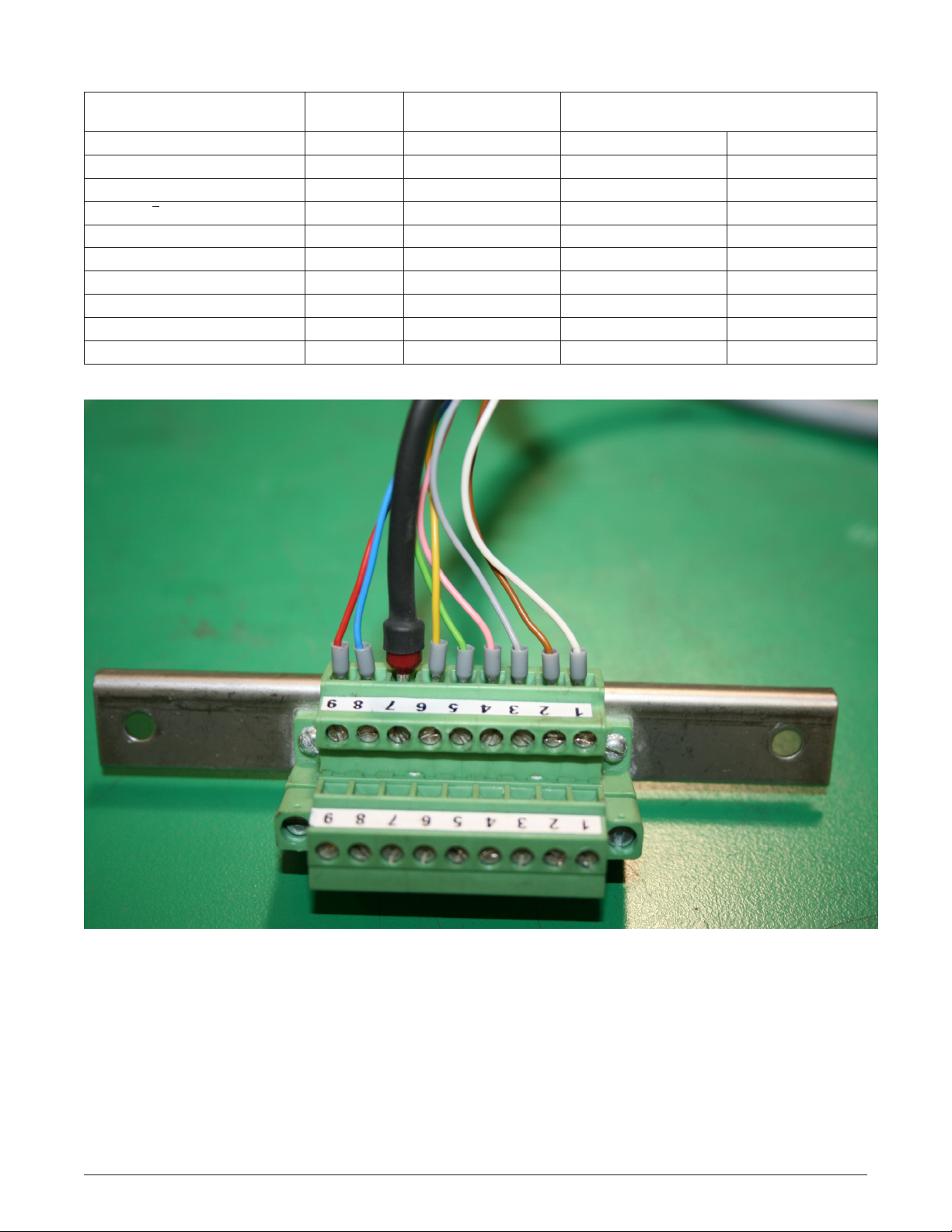
Wiring Diagram
Function Color
Electronics Ground white
Input Power (12-24 Vdc) brown
Channel "B" Output grey
Channel "B" Output pink
Channel "A" Output green
Channel "Ā" Output yellow
Shield black
Verication Pulse Output blue
Inverted Verication Pulse red
(Not used)
Standard Version Pin
Connections
[ 1 ]
[ 2 ]
[ 3 ]
[ 4 ]
[ 5 ]
[ 6 ]
[ 7 ]
[ 8 ]
[ 9 ]
[10]
Rotation of Transmitter Shaft Reference
Dimensions Drawing Below
Counter-Clockwise Clockwise
Leading Lagging
Lagging Leading
Figure 1 – Terminal Block Wires
Note: Picture in color, black and white, follow wire diagram table.
Issue/Rev. 0.7 (11/17) MN01045 • Page 3
 Loading...