

Smith GS110W User Manual
GS110IOM-2
GS110W
NATURAL OR PROPANE GAS BOILERS
INSTALLATION & OPERATION MANUAL
MEA#117-96-E
DESIGNED AND TESTED ACCORDING TO A.S.M.E. BOILER AND PRESSURE
VESSEL CODE, SECTION IV FOR A MAXIMUM ALLOWABLE WORKING PRESSURE
OF 50 PSI WATER.
TO INSTALLER
NOTE: READ THESE INSTRUCTIONS CAREFULLY. THEY
WILL SAVE YOU TIME IN ASSEMBLING BOILER PROPERLY.
WARNING: If the information in this manual is not followed exactly, a fire
or explosion may result causing property damage, personal injury or loss of life.
Do not store or use gasoline or other flammable vapors and liquids in the vicinity of
this or any other appliance.
WHAT TO DO IF YOU SMELL GAS:
• Do not try to light any appliance.
• Do not touch any electrical switch. Do not use any phone in your building.
• Immediately call your gas supplier from a neighbor’s phone. Follow the gas
supplier’s instructions.
• If you cannot reach your gas supplier, call the fire department.
INSTALLER, THESE INSTRUCTIONS TO BE AFFIXED ADJACENT TO THE HEATER.
CONSUMER, RETAIN THESE INSTRUCTIONS FOR FUTURE REFERENCE PURPOSES.
NOTE: Installation and service must be performed by a qualified installer, service
agency or the gas supplier.
260 NORTH ELM STREET WESTFIELD, MA 01085
TEL. (413) 562-9631 FAX: (413) 562-3799

GS110 DIRECT VENT BOILER INSTALLATION AND OPERATION INSTRUCTIONSPage 2
AVERTISSMENT. Assurez-vous de bien suivre les instructions données dans cette
notice pour réduire au minimum le risque d’incendie ou d’explosion ou pour éviter
tout dommoge matériel, toute blessure ou la mort
Ne pas entreposer ni utiliser d’essence ou ni d’autres vapeurs ou liquides inflammables
à proximité de cet appareil ou de tout autre appareil.
QUE FAIRE SI VOUS SENTEZ UNE ODEUR DE GAZ:
• Ne pas tenter d’allumer d’appareil.
• Ne touchez à aucun interrupteur; ne pas vous servir des téléphones se trouvant dans
le bâtiment.
• Appelez immédiatement votre fournisseur de gas depuis un voisin. Suivez les
intructions du fournisseur.
• Si vous ne purvez rejoindre le fournisseur, appelez le service des incendies.
L’installation et l’entretien doivent être assurés par un installateur ou un service
d’entretien qualifié ou par le fournisseur de gaz.
CONTENTS
Before You Start .................................................page 2
Boiler Ratings & Capacities................................ page 3
Boiler Location ................................................... page 3
Clearances to Combustible Construction ...........page 3
Combustion Air & Ventilation ..............................page 4
Chimney & Vent Pipe Connections .................. page 10
Heating System Piping .....................................page 15
Gas Supply Piping............................................ page 18
Electrical Wiring ............................................... page 18
Lighting Instructions .........................................page 22
Boiler Set Up ....................................................page 24
Boiler Operation ...............................................page 24
Checking & Adjusting .......................................page 25
Boiler Maintenance .......................................... page 26
Replacement Parts........................................... page 28
Instructions to the Installer ...............................page 31
Health Warnings ...............................................page 31
BEFORE YOU START
WARNING: This manual must be read and fully
understood before installing, operation or
servicing this boiler! Failure to follow these
instructions could result in a fire or explosion
causing extensive property damage, personal
injury or death!
Each unit has been constructed and hydrostatically
tested for a maximum working pressure of 30 psi in
accordance with the ASME Boiler and Pressure Vessel
Code, Section IV for cast iron boilers. Each boiler has
been equipped with a 30 psi pressure relief valve.
This manual covers the application, installation, operation
and maintenance of a GS110 low pressure hot water boiler.
To obtain the safe, dependable, efficient operation and
long life for which this boiler was designed, these
instructions must be read, understood and followed.
Direct all questions to your Smith Cast Iron Boiler
distributor or to the Customer Service Department, 260
North Elm Street, Westfield, MA 01085. Always include
the model and serial numbers from the rating plate of
the boiler in question.
The owner should maintain a record of all service work
performed with the date and a description of the work
done. Include the name of the service organization for
future reference.
Where required by the authority having jurisdiction, the
installation must conform to the Standard for Controls
and Safety Devices for Automatically Fired Boilers,
ANSI/ASME CSD-1.
These instructions cover the GS110 gas fired, direct
vent, low pressure, sectional, cast iron hot water boiler.
GS110 boilers have been design certified by CSA for
use with natural and propane gas under the latest
edition of ANSI-Z21.13/CSA 4.9, Gas-Fired Low
Pressure Steam and Hot Water Boilers.
If installed in the Commonwealth of Massachusetts, you
MUST FOLLOW the additional instructions contained in
Hydrotherm’s instruction sheet MA IOM. If you don’t have
a copy, call your Hydrotherm distributor or Hydrotherm.
GS110 DIRECT VENT BOILER INSTALLATION AND OPERATION INSTRUCTIONS Page 3
The installation must conform to the requirements of the
authority having jurisdiction or, in the absence of such
requirements, to the National Fuel Gas Code, ANSI
Z223.1-latest revision. In Canada, the installation must
be in accordance with the requirements of CSA B149.1
or B149.2 Installation Code for Gas Burning Appliances
and Equipment.
BOILER RATINGS & CAPACITIES
Before undertaking the installation of the GS110 check
the boiler rating plate to ensure that the boiler is the
proper size for the job. The "Net I=B=R Ratings" specify
the equivalent amount of direct cast iron radiation that
the boiler can handle under normal conditions.
Also ensure that the boiler has been set up for the type
of gas available at the installation site. Other important
considerations are the availability of an adequate
electrical supply, fresh air for combustion and proximity
a suitable outside wall.
BOILER LOCATION
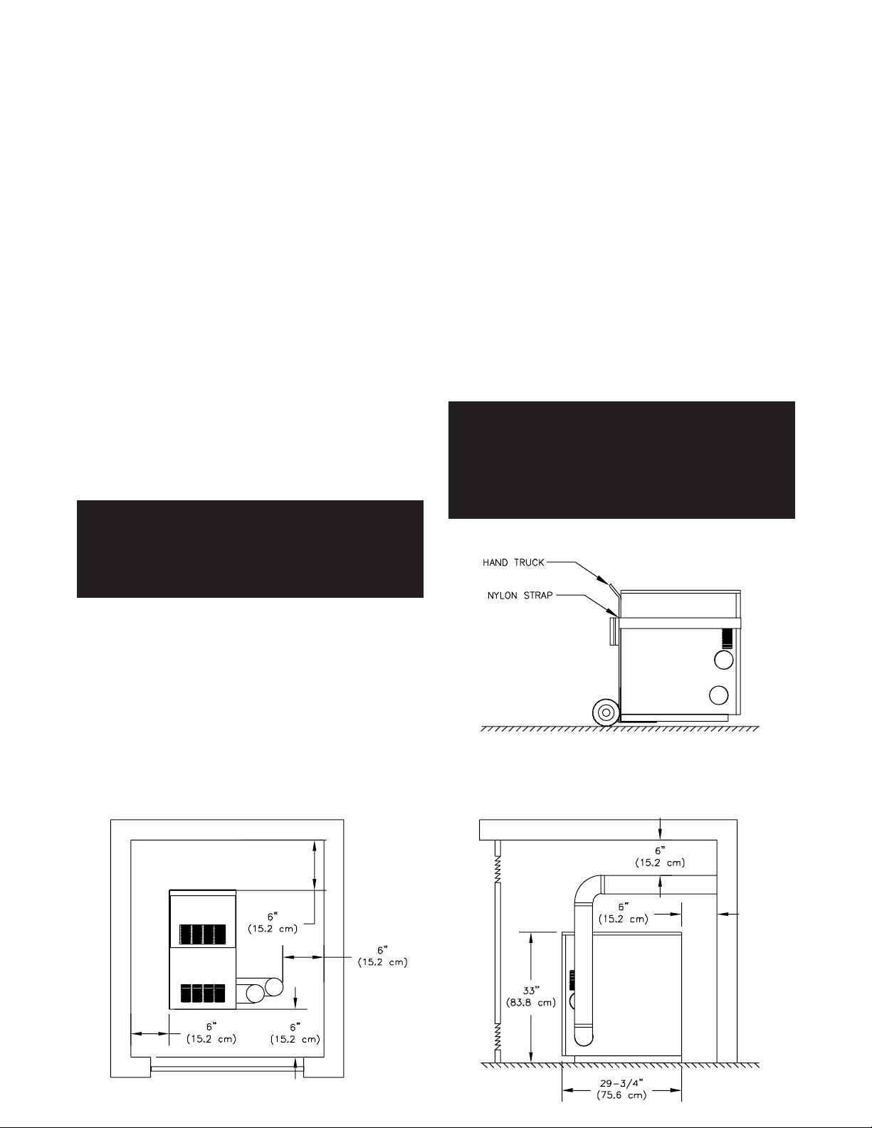
WARNING: The clearances to combustible
construction show in Figure 1 must be maintained. Failure to comply with this warning can
result in extensive property damage, severe
personal injury or death!
2. An optimum site will be level, central to the hot water
piping system, close to an outside wall and have
adequate fresh air for combustion.
3. Ensure that the floor is structurally sound and will
support the weight of the boiler.
NOTE: This boiler is designed for direct placement
on a combustible floor. Never install this boiler on
carpeting!
4. DO NOT install this boiler in a location that would
subject any of the gas ignition components to direct
contact with water or excessive moisture during
operation or servicing.
5. NEVER store objects on or around the boiler.
WARNING: Never store combustible materials,
gasoline or any product containing flammable
vapors or liquids in the vicinity of the boiler.
Failure to comply with this warning can result
in extensive property damage, severe personal
injury or death!
Figure 2 - Moving Boiler
CAUTION: Do not lift the boiler by the jacket. Use a
hand truck under the base frame as shown in Figure 2.
1. Locate the boiler in an area that provides good
access to the unit. Keep in mind that servicing may
require the removal of jacket panels. Accessibility
clearances must take precedence over fire
protection clearances.
Figure 1 - Clearances to Combustible Construction

GS110 DIRECT VENT BOILER INSTALLATION AND OPERATION INSTRUCTIONSPage 4
COMBUSTION AIR & VENTILATION
WARNING: This boiler must be supplied with
combustion air in accordance with Section 5.3,
Air for Combustion & Ventilation, of the latest
revision of the National Fuel Gas Code, ANSI
Z223.1/NFPA 54 and all applicable local building
codes. Canadian installations must comply with
CSA B149.1 or .2 Installation Code for Gas
Burning Appliances and Equipment, or
applicable provisions of the local building
codes. Failure to provide adequate combustion
air for this boiler/water heater can result in
excessive levels of carbon monoxide which can
result in severe personal injury or death!
To operate properly and safely this boiler requires a
continuous supply of air for combustion. NEVER store
objects on or around the boiler!
CAUTION: Combustion air contaminated with
fluorocarbons or other halogenated compounds
such as cleaning solvents and refrigerants will
result in the formation of acids in the combustion
chamber. These acids will cause premature failure
of the boiler voiding the warranty!
CAUTION: If the boiler is operated while the building
is under construction it MUST be protected from
wood, concrete, sheet rock and other types of dust.
Failure to properly protect the unit from
construction dust will damage the unit voiding the
warranty!
Buildings may require the installation of a fresh air duct
or other means of providing make-up air if the intake
air option isn't used. Any building utilizing other gas
burning appliances, a fireplace, wood stove or any type
of exhaust fan must be checked for adequate
combustion air when all of these devices are in
operation at one time. Sizing of an outside air duct must
be done to meet the requirements of all such devices.
WARNING: Never operate this boiler in an
environment subjected to a negative pressure
unless the air intake is connected to the
outdoors. Failure to comply with this warning
can result in excessive levels of carbon
monoxide causing severe personal injury or
death!
All Combustion Air From Inside The Building
Older houses often have enough “leakage” to provide
an adequate amount of combustion air provided that the
demand for combustion air is not too great, Figure 3.
Homes that are relatively new or “tight” will most likely
require that the combustion be ducted to the boiler from
outside the building. Any home utilizing other gas
burning appliances, a fireplace, wood stove or any type
of exhaust fan must be checked for adequate
combustion air when all of these devices are in
operation at one time.
If the boiler is to be located in an alcove, closet or other
confined space the distances from the boiler and it's
vent system to all-combustible construction must be
equal to or greater than the minimum clearances in
Figure 1. When installed in a closet or confined space
two permanent openings of equal area adjoining another
room or rooms having sufficient volume to meet the
requirements of an unconfined space must be provided,
Figures 4 & 5. Each opening must have a minimum free
area of one square inch per 1000 Btu/hr (2200 mm
kW) based on the total input rating of all gas utilization
equipment in the confined area. Each opening must be
no less than 100 square inches (64516 mm2) in size.
The upper opening must be within 12 inches (305 mm)
of, but not less than 3 inches (76 mm) from, the top of
the enclosure. The bottom opening must be within 12
inches (305 mm) of, but not less than 3 inches (76 mm)
from, the bottom of the enclosure.
All Combustion Air From Outside The Building
When installed in a confined space without the intake
air option two permanent openings communicating
directly with, or by ducts to, the outdoors or spaces that
freely communicate with the outdoors must be present.
The upper opening must be within 12 inches (305 mm)
of, but not less than 3 inches (76 mm) from, the top of
the enclosure. The bottom opening must be within 12
inches (305 mm) of, but not less than 3 inches (76 mm)
from, the bottom of the enclosure.
Where directly communicating with the outdoors or
communicating with the outdoors through vertical ducts,
each opening shall have a minimum free area of 1 in2/
4000 Btu/hr (550 mm2/kW) of the total input rating of
all of the equipment in the enclosure.
Where communicating with the outdoors through horizontal ducts, each opening shall have a minimum free
area of 1 in2/2000 Btu/hr (1100 mm2/kW) of the total
input rating of all of the equipment in the enclosure.
2
/
When ducts are used, they must have the same crosssectional area as the free area of the opening to which
they connect. Sizing of an outside air duct must be
based on the total input rating of all gas utilization
equipment in the confined space.
GS110 DIRECT VENT BOILER INSTALLATION AND OPERATION INSTRUCTIONS Page 5
When calculating the free area necessary to meet the
make-up air requirements of the enclosure,
consideration must be given to the blockage effects of
louvers, grills and screens.
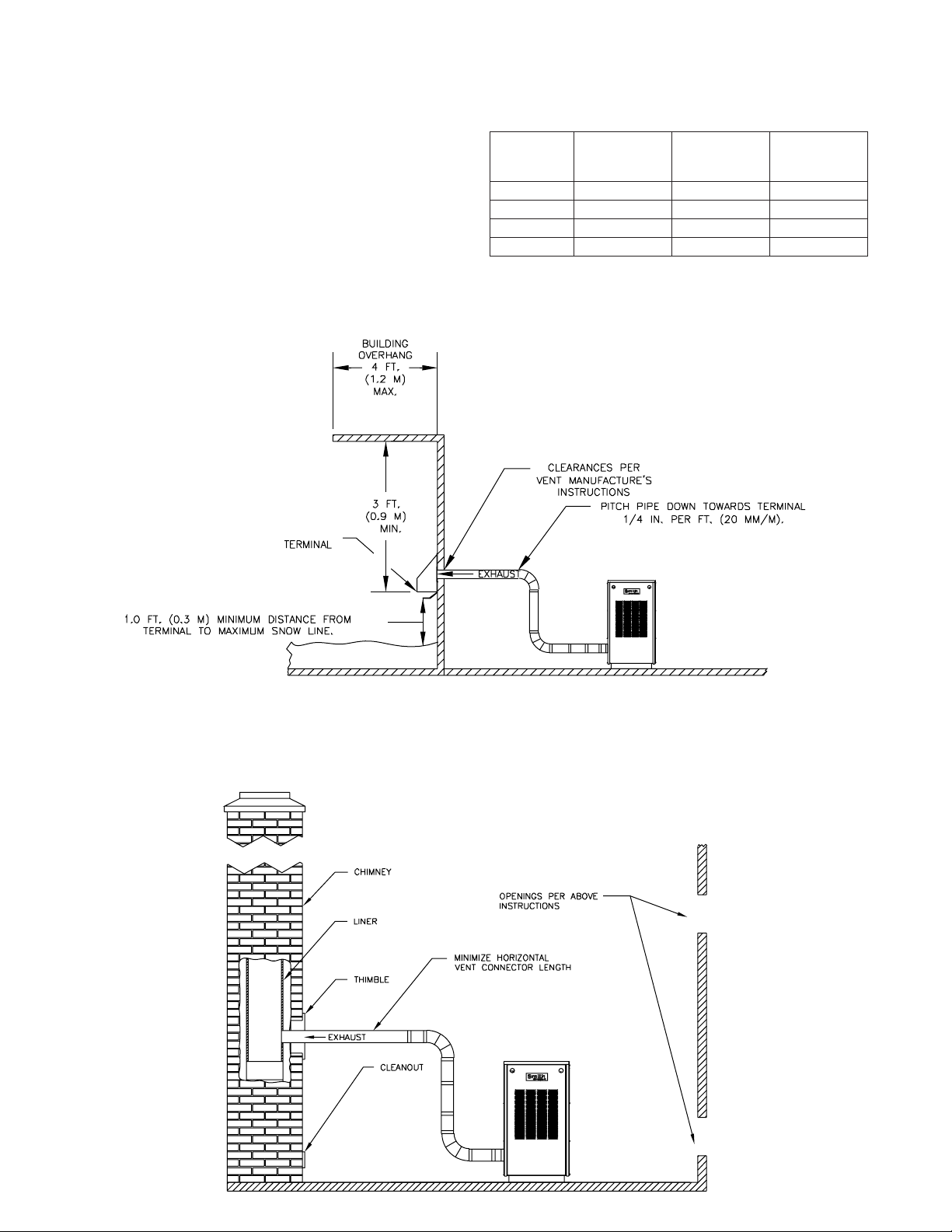
Screens must have a minimum mesh size of 1/4"
(6.4mm). If the free area through a louver or grill is not
known ducts should be sized per Table 1.
Table 1 - Combustion Air Duct Sizing
FreshAir
Duct Size
3” x 12”
8” x 8”
8” x 12”
8-1/2” x 16”
Input Btuh
1/4” Wire
Screen Mesh
144,000
256,000
384,000
512,000
Input Btuh
Figure 3 - Horizontal Positive Pressure Venting Using Inside Combustion Air (Cat. III)
Metal
Louvers
108,000
192,000
288,000
384,000
Input Btuh
Wooden
Louvers
36,000
64,000
96,000
128,000
Figure 4 - Vertical Negative Pressure Masonry Chimney System Using Inside Combustion Air (Cat. I)
GS110 DIRECT VENT BOILER INSTALLATION AND OPERATION INSTRUCTIONSPage 6
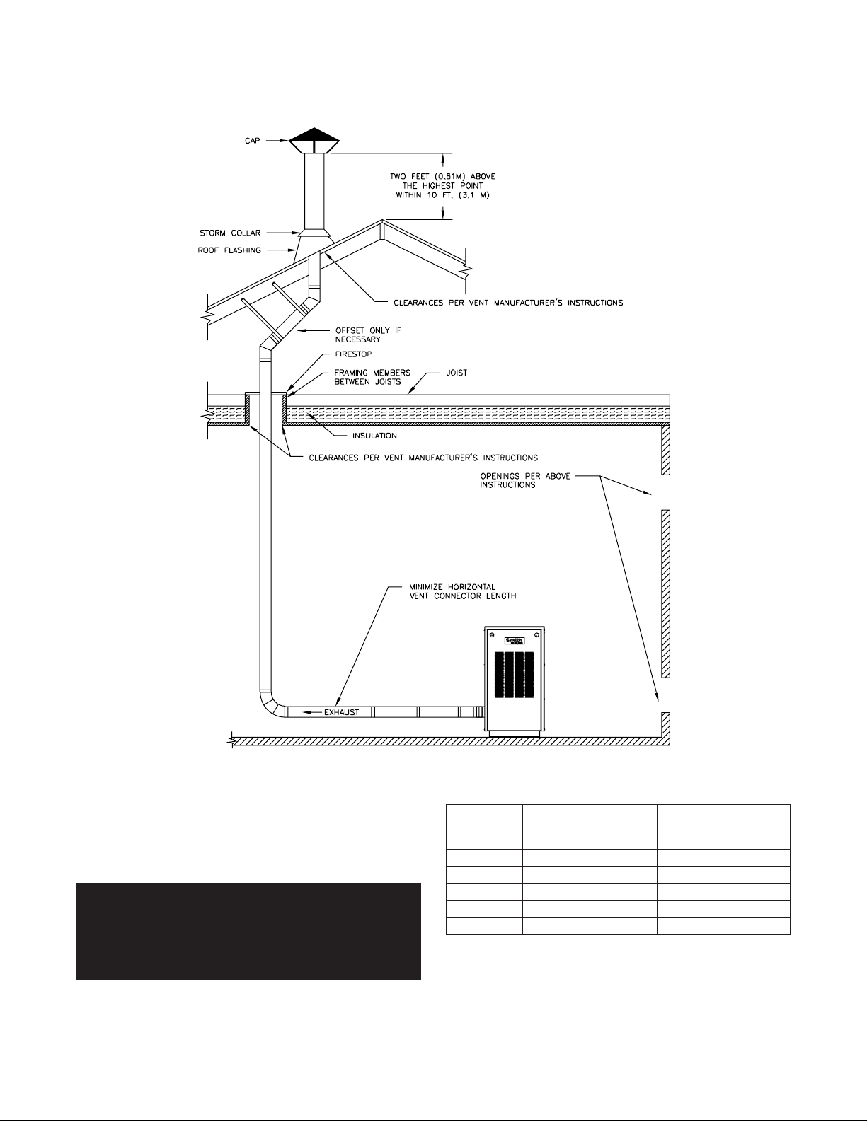
Figure 5 - Vertical Negative Pressure Metal Chimney System and Inside Combustion Air (Cat. I)
Intake Air Option - General Guidelines
This configuration provides combustion air directly to the
boiler using a dedicated pipe. Combustion air can be
drawn in horizontally through an outside wall or vertically
through the roof, see Figures 6, 7, 8, 9 & 10.
WARNING: Each boiler must have it's own intake
air system. Common intake air systems are not
to be used! Improper installation can result in
excessive levels of carbon monoxide which can
cause severe personal injury or death!
Single wall galvanized smoke pipe, single wall aluminum
pipe, flexible aluminum pipe, PVC or CPVC pipe can be
used for the intake air pipe. Maximum intake lengths
must not be exceeded per Table 2, larger diameters may
be used on 3,4,and 5 section boilers.
Table 2 - Combustion Air System Sizing
Boiler
Model
Number
GS110-3
GS110-4
GS110-5
GS110-6
GS110-7
Equivalent Intake
Length (see note)
3” Diameter
45 feet (13.7 m)
45 feet (13.7 m)
45 feet (13.7 m)
n/a
n/a
Equivalent Intake
Length (see note)
4” Diameter
65 feet (19.8 m)
65 feet (19.8 m)
65 feet (19.8 m)
* 40 feet (12.2 m)
* 40 feet (12.2 m)
* 4" to 3" reducer required.
Note: Subtract 5 feet (1.5 m) for each 90° elbow.
GS110 DIRECT VENT BOILER INSTALLATION AND OPERATION INSTRUCTIONS Page 7
All joints in metal intake air systems must be secured
using corrosion resistant fasteners and sealed using a
suitable Silicone caulk. If PVC or CPVC is used, the
joints must be cleaned with a suitable solvent and
connected using a solvent based PVC cement. The
intake air system MUST be supported by the building
structure not the boiler/water heater.
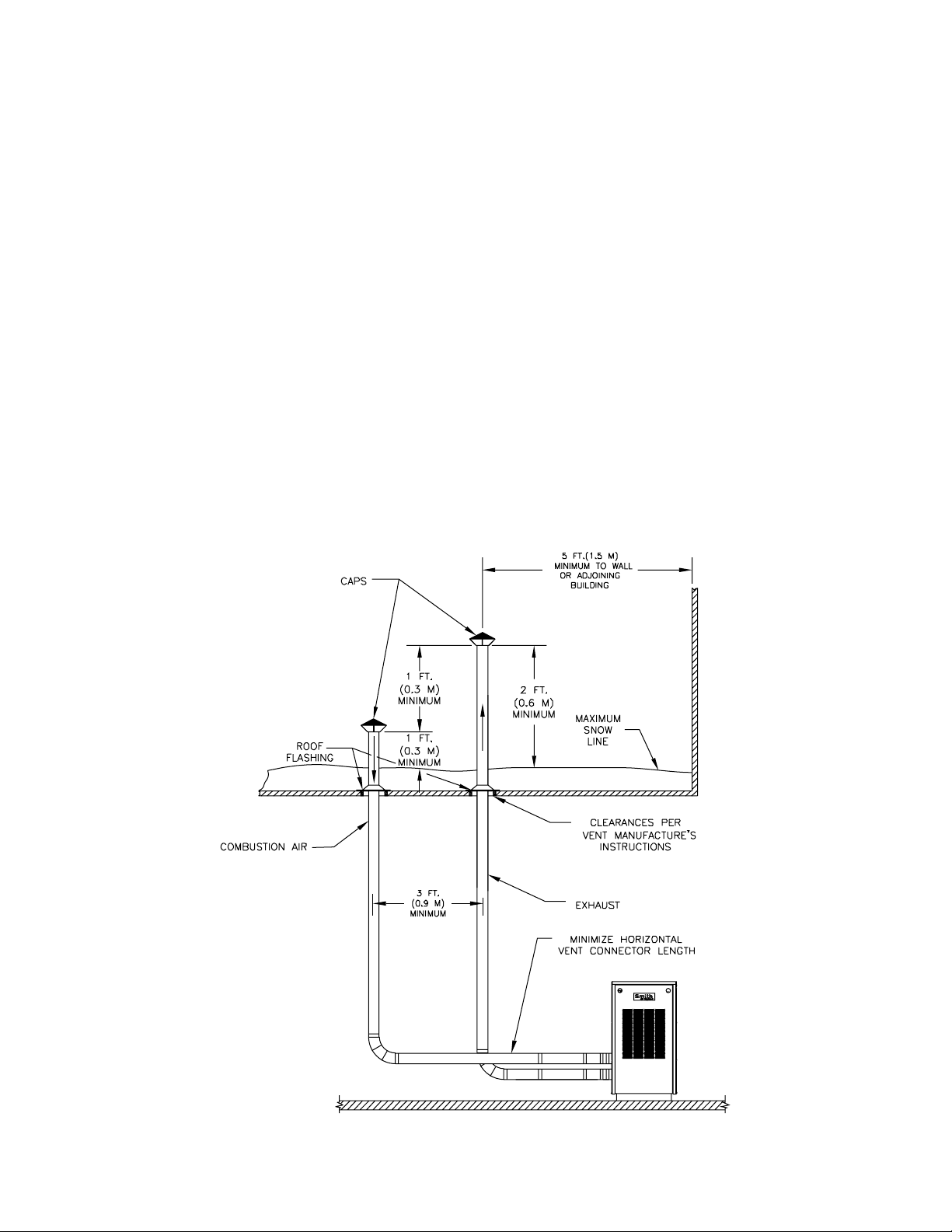
Intake Air Option - Vertical Guidelines
A listed, nonrestrictive intake air cap must be used. The
intake air cap must terminate as shown in Figure 6. The
penetration point in the roof must be properly flashed
and sealed.
Figure 6 - Vertical Positive Pressure Venting with Outdoor Combustion Air (Cat. III)
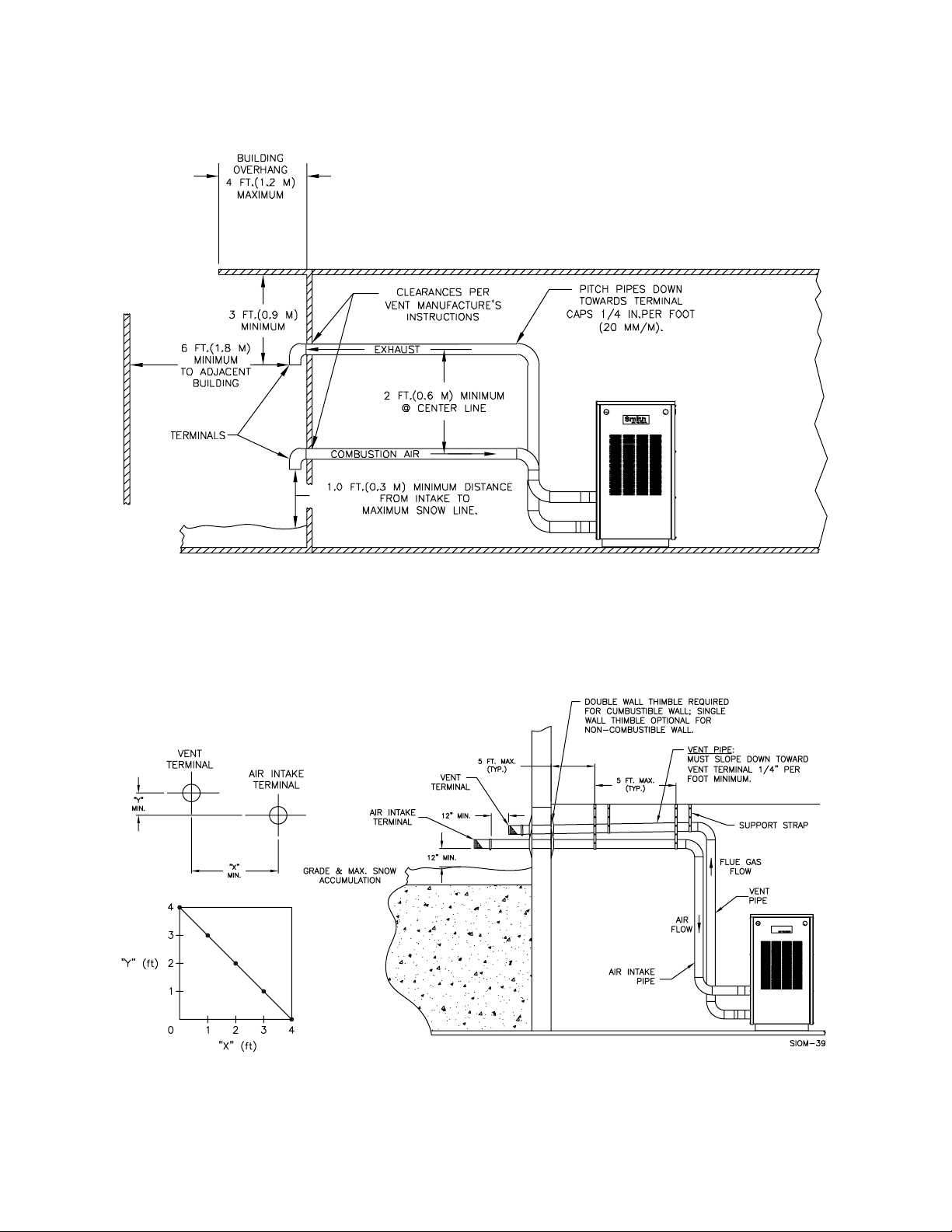
Intake Air Optional - Horizontal Guidelines
The maximum equivalent length for the horizontal intake
air pipe is listed in Table 2. The intake air system must
be pitched down, toward the terminal, 1/4" per foot
(21 mm per meter).
If horizontal runs exceed 5 feet (1.5 m) they must be
supported at 3 foot (0.98 m) intervals with overhead
hangers. Figures 7 through 10 show the four horizontal
air intake options. The intake terminations certified for
use the GS110 are listed in Table 5.
GS110 DIRECT VENT BOILER INSTALLATION AND OPERATION INSTRUCTIONSPage 8
Figure 7 - Horizontal Positive Pressure Venting with Outdoor Combustion Air
Figure 8 - Horizontal Positive Pressure Venting with Outdoor Combustion Air
Smith
GS110 DIRECT VENT BOILER INSTALLATION AND OPERATION INSTRUCTIONS Page 9
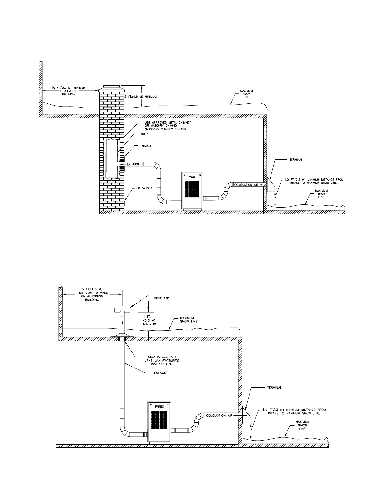
Figure 9 - Vertical Negative Pressure Masonry Chimney System using Outside Combustion Air (Cat. I)
Figure 10 - Vertical Positive Pressure Venting using Outside Combustion Air (Cat. III)
GS110 DIRECT VENT BOILER INSTALLATION AND OPERATION INSTRUCTIONSPage 10
GENERAL VENTING GUIDELINES
WARNING: The vent installation must be in
accordance with Part 7, Venting of Equipment,
of the National Fuel Gas Code, ANSI Z223.1/
NFPA 54-latest revision or applicable provisions
of the local building codes. Canadian
installations must comply with CSA B149.1 or
.2 Installation Code. Improper venting can result
in excessive levels of carbon monoxide which
can result in severe personal injury or death!
WARNING: Thimbles and fire-stops must be
used where required. A minimum clearance of
6" must be maintained between single wall
metal vents and combustible construction or a
fire resulting in severe personal injury or death
may occur!
WARNING : Each boiler/water heater must have
it's own vent system. Common positive
pressure vent systems are not to be used!
Improper installation can result in excessive
levels of carbon monoxide which can cause
severe personal injury or death!
All vent systems must be fully supported by the building
structure and not by the boiler/water heater.
VENT SYSTEM OPTIONS
The GS110 may be vented the following ways:
Certified vent systems are manufactured by the following
companies:
Heat-fab, Inc.
130 Industrial Blvd., Turners Falls, MA 01376
(800) 772-0739.
Z-Flex U.S., Inc.
20 Commerce Park North, Bedford, NH 03110-6911
(800) 654-5600.
Protech Systems Inc.
26 Gansevoort Street, Albany, NY 12202
(518) 463-7284
GENERAL DIRECT VENT INFO
In this configuration the boiler blower is used to push the
flue products to the outdoors while drawing combustion
air from the outdoors. The instructions under the
COMBUSTION AIR & VENTILATION SECTION must be
followed! The vent system must be sized per Table 3.
Table 3 - Positive Pressure Vent System Sizing
Boiler
Model
Number
GS110-3
GS110-4
GS110-5
GS110-6
GS110-7
Equivalent Vent
Length (see note)
3” Diameter
45 feet (13.7 m)
45 feet (13.7 m)
45 feet (13.7 m)
n/a
n/a
* 4" to 3" reducer required
Note: Subtract 5 feet (1.5 m) for each 90° elbow.
Equivalent Vent
Length (see note)
4” Diameter
*65 feet (19.8 m)
*65 feet (19.8 m)
*65 feet (19.8 m)
40 feet (12.2 m)
40 feet (12.2 m)
1) Direct Vent (Positive Pressure), uses a vent system
certified to UL 1738 for installations in the United States,
ULS636 for installations in Canada. Combustion air is
piped from the outdoors to the blower inlet.
2) Horizontal Vent (Positive Pressure), uses a vent
system certified to UL 1738 for installations in the United
States, ULS636 for installations in Canada. Combustion
air is obtained from the space in which the unit is installed.
3) Vertical Vent (Positive Pressure), uses a vent system
certified to UL 1738 for installations in the United States,
ULS636 for installations in Canada. Combustion air is
piped from the outdoors to the blower inlet or is obtained
from the space in which the unit is installed.
4) Vertical/Chimney Vent (Negative Pressure), uses an
approved metal chimney system or masonry chimney.
Combustion air is obtained from the space in which the
unit is installed or is piped from the outdoors to the blower
inlet.
HORIZONTAL DIRECT VENT
SYSTEMS
See figures 7 & 8. The vent materials used in horizontal
positive pressure vent systems must be certified to UL
1738 for installations in the United States, ULS636 for
installations in Canada.
Each 90° elbow is equal to 5 linear feet (1.5 m) of pipe.
To maximize the performance of single wall sheet metal
vent systems locate 90° elbows as far from the boiler as
possible and from one another. For best results, horizontal
vent systems should be as short and straight as possible.
The vent system must be both gas tight and watertight.
All seams and joints in metal pipes must be joined and
sealed in accordance with the vent system manufacturer’s
instructions.
When horizontal vent runs exceed 5 feet (1.5m) they must
be supported at 3 foot (0.98 m) intervals with overhead
hangers. The vent system must be pitched down, toward
the vent terminal, 1/4" per foot (21mm per meter). If any
part of a single wall metal vent system passes through
an unheated space it must be insulated with insulation
rated for 400°F. Structural penetrations must be made
using approved thimbles.
 Loading...