

smirthwaite Zoomi 13011, Zoomi 13021, Zoomi 13031, Zoomi+ 13012, Zoomi+ 13022 User Manual
...Page 1
6/17
ZOOMI
INSTRUCTIONS FOR USE
Zoomi 13011, 13021, 13031 / Zoomi+ 13012, 13022, 13032
Page 2

!
ZOOMI%AND%ZOOMI%+!
1%
!!!!!!!!!!!!!!!!!!!!!!!!!!!!!!!!!!!!!!!!!!!!!!!!!!!!!!!!!!!!!!!!!!!!!!!!!!!!!!!!!!!!!!!!!!!!!!!!!!!!!!!!!!!!!!!!!!!!!!!
CONTENTS PAGE
1.0 INTRODUCTION 1
2.0 ILLUSTRATION OF YOUR ZOOMI SEATING SYSTEM 2
3.0 ILLUSTRATION OF YOUR ZOOMI + SEATING SYSTEM 3
4.0 PRODUCT CODES REFERENCE TABLE 4
5.0 TECHNICAL DATA 4
6.0 FOR YOUR SAFETY 5
7.0 ASSEMBLING AND ADJUSTING YOUR ZOOMI 6
8.0 CARE & MAINTENANCE 19
9.0 WARRANTY & SERVICE 22
10.0 CONTINUOUS IMPROVEMENT 22
11.0 SERVICE INSPECTION 23
1.0 INTRODUCTION
Thank you for choosing the ZOOMI seating system from Smirthwaite.
The ZOOMI seating system has been designed with versatility and functionality in
mind. It is a seating solution which grows with your child; from toddler to teen,
encouraging social inclusion in both the home and school environment.
A wide range of optional accessories are available to purchase to suit your client’s
specific needs; please contact your area sales representative for further details.
IMPORTANT!
These instructions should be read by all therapists and carers using the
equipment and should be retained for future reference. The product should
always be used under adult supervision.
Any incorrect use of the product and failure to follow the instructions may
put the user at risk or impede the function. If you have any queries using
this product or wish for further copies, please do not hesitate to contact
Customer Service department.
Contact: Smirthwaite Ltd
T: +44 (0)1626 835552
F: +44 (0)1626 835428
E: info@smirthwaite.co.uk
Page 3
!
ZOOMI%AND%ZOOMI%+!
2%
!!!!!!!!!!!!!!!!!!!!!!!!!!!!!!!!!!!!!!!!!!!!!!!!!!!!!!!!!!!!!!!!!!!!!!!!!!!!!!!!!!!!!!!!!!!!!!!!!!!!!!!!!!!!!!!!!!!!!!!
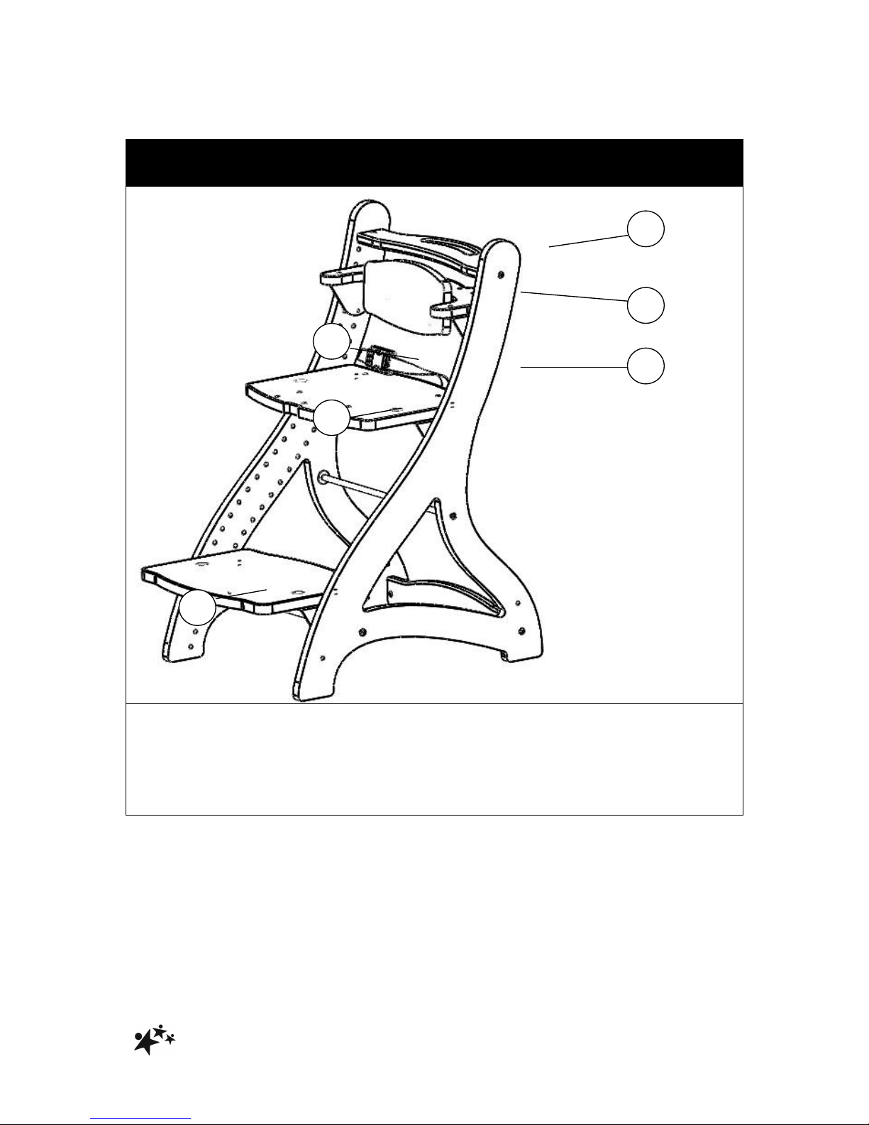
2.0 ILLUSTRATION OF YOUR ZOOMI SEATING SYSTEM
Zoomi
Main frame
Pelvic lap strap
Seat board
Foot board
Back rest
Push handle
1 2 3 4 5
6
Page 4

!
ZOOMI%AND%ZOOMI%+!
3%
!!!!!!!!!!!!!!!!!!!!!!!!!!!!!!!!!!!!!!!!!!!!!!!!!!!!!!!!!!!!!!!!!!!!!!!!!!!!!!!!!!!!!!!!!!!!!!!!!!!!!!!!!!!!!!!!!!!!!!!
3.0 ILLUSTRATION OF YOUR ZOOMI + SEATING SYSTEM
Zoomi +
Main frame
5 point harness
Padded seat board
Slotted foot board
Mobile Skis
Arm rest
Padded back rest
Push handle
Quick release tray
1 2 8 9 4 5 6 3 7
Page 5

!
ZOOMI%AND%ZOOMI%+!
4%
!!!!!!!!!!!!!!!!!!!!!!!!!!!!!!!!!!!!!!!!!!!!!!!!!!!!!!!!!!!!!!!!!!!!!!!!!!!!!!!!!!!!!!!!!!!!!!!!!!!!!!!!!!!!!!!!!!!!!!!
4.0 PRODUCT CODES REFERENCE TABLE
PRODUCT
/ CLOUOR
RED
LIME
BLUE
ZOOMI
13011
13021
13031
ZOOMI+
13012
13022
13032
5.0 TECHNICAL DATA
ZOOMI Seating System
Dimension
All measured in mm
Frame (H x W x D)
810 x 450 x 550
Seat board (W x D)
430 x 300
Foot board (W x D)
430 x 300
Seat back rest (H x D)
130 x 270
Seat height from floor (max – min)1
400 – 650
Foot board height from floor (max –
min)
1,2
260 - 600
Back rest height from floor (max – min) 1
500 - 720
Adjustment interval
25
Maximum user weight (kg)
85
Notes:
1. Ranges given are recommendations only – further adjustment range is possible
2. Foot board can be removed, leaving option of foot flat to floor
Page 6

!
ZOOMI%AND%ZOOMI%+!
5%
!!!!!!!!!!!!!!!!!!!!!!!!!!!!!!!!!!!!!!!!!!!!!!!!!!!!!!!!!!!!!!!!!!!!!!!!!!!!!!!!!!!!!!!!!!!!!!!!!!!!!!!!!!!!!!!!!!!!!!!
6.0 FOR YOUR SAFETY
STOP!
Please read these instructions CAREFULLY and THOROUGHLY.
The user should NOT be left unattended whilst in the product. Always ensure a
responsible therapist or carer is in attendance
The carer should be familiar with the methods of adjustment and have completed all
adjustments appropriately to meet the needs of the child before transferring the child
onto the product
Regular maintenance checks and cleaning are essential for the safe use of this
equipment (see care and maintenance section)
Ensure that all nuts, bolts and hand wheels are securely tightened and that none are
missing
The product is ONLY to be used indoors on a flat level surface
Do NOT exceed the maximum user weight of 85kg
Always fasten the lap strap harness and any other straps provided with the product
Always keep this product away from naked flames, cigarettes and sources of heat
including open fireplaces, radiators and heaters
DO NOT fit parts or accessories of other manufacturers to this product unless
authorized to do so in writing by Smirthwaite Ltd. Failure to follow these instructions
will not only invalidate the guarantee but could make the product dangerous to use.
Smirthwaite Ltd will not accept liability for any injury or damage incurred through
such malpractices
Any repairs required must be carried out by Smirthwaite Ltd authorized personnel
STOP!
LAP STRAPS & HARNESSES SAFETY NOTICE
Lap straps and harnesses must be appropriate and safe for the user and
the users clothing.
Lap straps and harnesses must be checked every time the chair is used to
ensure they are fitted as prescribed by the clinician, take account of the
users clothing and are tightened so that the user cannot sustain injury.
Checking the fit of lap straps and harnesses must be done with the user in
the chair and should be undertaken as soon as the users sits in the chair.
STOP!
If you believe this product to be faulty – DO NOT USE
Contact: Smirthwaite Ltd
T: +44 (0)1626 835552
F: +44 (0)1626 835428
E: info@smirthwaite.co.uk
Page 7
!
ZOOMI%AND%ZOOMI%+!
6%
!!!!!!!!!!!!!!!!!!!!!!!!!!!!!!!!!!!!!!!!!!!!!!!!!!!!!!!!!!!!!!!!!!!!!!!!!!!!!!!!!!!!!!!!!!!!!!!!!!!!!!!!!!!!!!!!!!!!!!!
7.0 ASSEMBLY AND ADJUSTMENT OF YOUR ZOOMI SEATING SYSTEM
STOP!
If in any doubt, ALWAYS seek ADVICE.
Always turn hand wheels, levers and screws clockwise to tighten or anticlockwise to loosen.
When delivered, the product will be supplied flat packed, and will require assembly
and setting up to suit your client’s need.
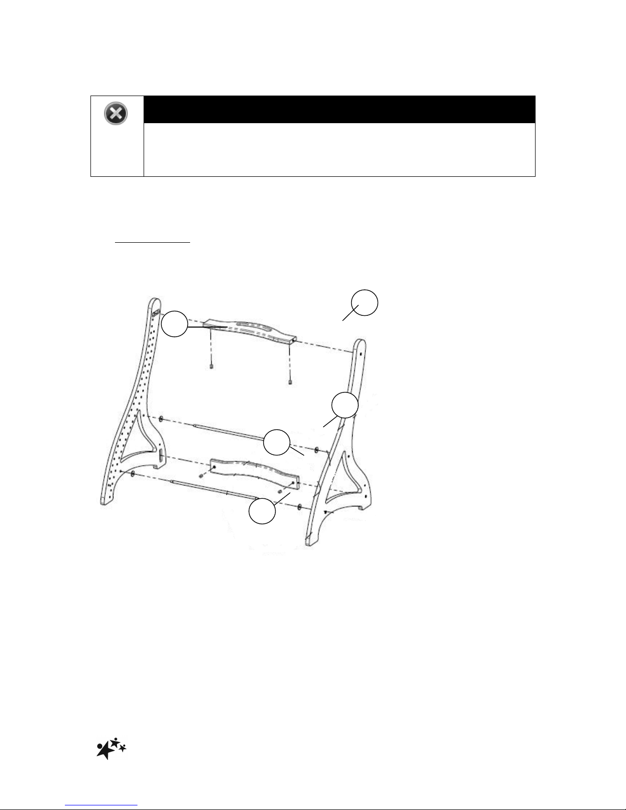
7.1 SEAT FRAME
Assembly of the ZOOMI seat frame is the first task.
A B B C E
Page 8
!
ZOOMI%AND%ZOOMI%+!
7%
!!!!!!!!!!!!!!!!!!!!!!!!!!!!!!!!!!!!!!!!!!!!!!!!!!!!!!!!!!!!!!!!!!!!!!!!!!!!!!!!!!!!!!!!!!!!!!!!!!!!!!!!!!!!!!!!!!!!!!!
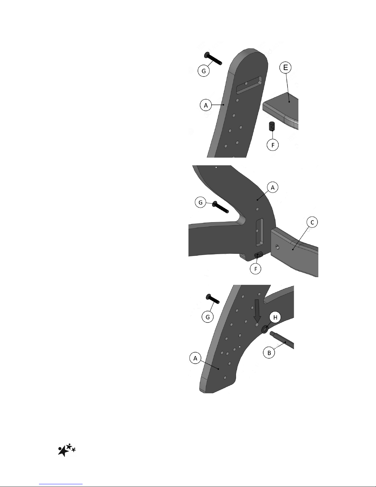
Insert one end of the Handle (E) into
frame side (A).
Insert a M6 cross dowel (F) into the
underside of the Handle (E).
Fix together by inserting a M6 x 40
bolt (G) through the hole in frame
side (A) and into the M6 cross dowel
(F) now held in Handle (E).
Insert one end of the cross bar (C)
into frame side (A).
Insert a M6 cross dowel (F) into the
face of the cross bar (C).
Fix together by inserting a M6 x 40
bolt (G) through the hole in frame
side (A) and into the M6 cross dowel
(F) now held in cross bar (C).
Insert tie bar (B) into the frame side
(A) through the hole (arrowed, right),
ensuring a M8 washer (H) is fitted.
Fix together by inserting the M6 x 30
bolt (G) through the hole in fame
side (A) and into the end of the tie
bar (B)
Repeat this process for the second
tie bar
Page 9

!
ZOOMI%AND%ZOOMI%+!
8%
!!!!!!!!!!!!!!!!!!!!!!!!!!!!!!!!!!!!!!!!!!!!!!!!!!!!!!!!!!!!!!!!!!!!!!!!!!!!!!!!!!!!!!!!!!!!!!!!!!!!!!!!!!!!!!!!!!!!!!!
Repeat the above steps for the second frame
side, to complete the seat frame assembly
STOP!
Ensure all screws are TIGHTENED on the Seat Frame before continuing
assembly
SEAT PREPARATION
FOOT BOARD PREPARATION
Page 10

!
ZOOMI%AND%ZOOMI%+!
9%
!!!!!!!!!!!!!!!!!!!!!!!!!!!!!!!!!!!!!!!!!!!!!!!!!!!!!!!!!!!!!!!!!!!!!!!!!!!!!!!!!!!!!!!!!!!!!!!!!!!!!!!!!!!!!!!!!!!!!!!
7.2 SEAT BOARD/PADDED SEAT (PLUS)/CONTOURED SEAT (ACCESSORY)
Take a support bracket (J) and insert into frame side (A) at the appropriate height for
the seat board to suit your client’s needs.
Repeat this step by taking a second support bracket (J) and inserting at the same
height on the second frame side
The support brackets (J) simply push into the frame sides
Carefully place and rest the seat board (I) on top of the support brackets – the
threaded bolt on the underside of the seat board fits through the hole in support
bracket (J)
Fit a hand wheel (K) and washer (L) – do not tighten at this time.
Repeat this step by fitting the second hand wheel into the seat board using the
second support bracket.
Slide the seat board forward/back to achieve the desired seat depth before
tightening the hand wheels to secure in place
To adjust the seat board height to suit child growth, simply reposition the support
brackets (J) as necessary.
ZOOMI/ZOOMI +
I A J
K
L
Page 11

!
ZOOMI%AND%ZOOMI%+!
10%
!!!!!!!!!!!!!!!!!!!!!!!!!!!!!!!!!!!!!!!!!!!!!!!!!!!!!!!!!!!!!!!!!!!!!!!!!!!!!!!!!!!!!!!!!!!!!!!!!!!!!!!!!!!!!!!!!!!!!!!
7.3 FOOT BOARD/SLOTTED FOOT BOARD (PLUS)/TRANSFER STEP
(ACCESSORY)
Take a support
bracket (J) and insert
into frame side (A) at
the appropriate height
for the foot board to
suit your client’s
needs.
Repeat this step by
taking a second
support bracket (J)
and inserting at the
same height on the
second frame side
The support brackets
(J) simply push into
the frame sides
Carefully place and rest the foot board (M) on top of the support brackets - the
threaded bolt on the underside of the seat board fits through the hole in support
bracket (J)
Fit a hand wheel (K) and washer (L) – do not tighten at this time.
Repeat this step by fitting the second hand wheel into the foot board using the
second support bracket.
Slide the foot board forward/back to achieve the desired foot board depth before
tightening the hand wheels to secure in place
To adjust the foot board height to suit growth, simply reposition the support brackets
(J) as necessary.
ZOOMI
ZOOMI +
M A J L K
Page 12

!
ZOOMI%AND%ZOOMI%+!
11%
!!!!!!!!!!!!!!!!!!!!!!!!!!!!!!!!!!!!!!!!!!!!!!!!!!!!!!!!!!!!!!!!!!!!!!!!!!!!!!!!!!!!!!!!!!!!!!!!!!!!!!!!!!!!!!!!!!!!!!!
7.4 BACK REST FRAME/ARM RESTS (PLUS)
Take a support bracket (O) and
insert into frame side (A) at the
appropriate height for the back rest
to suit your client’s needs.
Repeat this step by taking a second
support bracket (O) and inserting at
the same height on the second
frame side
Note: Support brackets (O) are
different from those used as support
brackets on the foot board and seat
board (J)
The support brackets (O) simply
push into the frame sides
Carefully place and rest the back rest frame (N) on top of the support brackets (O)
Secure the back rest frame (N) to the brackets (O) by inserting and tightening 4 x M6
x 16 flat screws (P), using the hex key provided
Note: 2 x M6 x 16 flat screws used per side.
ZOOMI
ZOOMI +
Page 13

!
ZOOMI%AND%ZOOMI%+!
12%
!!!!!!!!!!!!!!!!!!!!!!!!!!!!!!!!!!!!!!!!!!!!!!!!!!!!!!!!!!!!!!!!!!!!!!!!!!!!!!!!!!!!!!!!!!!!!!!!!!!!!!!!!!!!!!!!!!!!!!!
7.5 BACK REST/HIGH BACK REST (ACCESSORY)
Take a support bracket (S) and fix onto back rest frame (N) using 2 x M6 x 16 bolts
(Q) as shown above – a hex key is provided.
Repeat this step to secure a second support bracket (S) onto the back rest frame (N).
Now offer up the back rest wood (T) and secure onto bracket (S) using 4 x M6 x 12
button head screws (R)
ZOOMI
ZOOMI +
Page 14

!
ZOOMI%AND%ZOOMI%+!
13%
!!!!!!!!!!!!!!!!!!!!!!!!!!!!!!!!!!!!!!!!!!!!!!!!!!!!!!!!!!!!!!!!!!!!!!!!!!!!!!!!!!!!!!!!!!!!!!!!!!!!!!!!!!!!!!!!!!!!!!!
7.6 PELVIC LAP STRAP
A padded pelvic lap strap is provided for your client’s safety.
6.6.1 PELVIC LAP STRAP BUCKLE OPERATION
Press areas (U) to unlock the buckle and pull the two buckle parts apart.
To fasten simply reconnect the two parts – the buckle will ‘click’ and lock.
Page 15

!
ZOOMI%AND%ZOOMI%+!
14%
!!!!!!!!!!!!!!!!!!!!!!!!!!!!!!!!!!!!!!!!!!!!!!!!!!!!!!!!!!!!!!!!!!!!!!!!!!!!!!!!!!!!!!!!!!!!!!!!!!!!!!!!!!!!!!!!!!!!!!!
7.7 FIVE POINT HARNESS (PLUS/ACCESSORY)
The ZOOMI PLUS is supplied with a 5 point buckle release harness
Feed the 4 straps through cam locks (1,2,3 & 4 below)
Insert the hand wheel through a strap eyelet and into seat board (5, below)
1!2!34!5!
Page 16

!
ZOOMI%AND%ZOOMI%+!
15%
!!!!!!!!!!!!!!!!!!!!!!!!!!!!!!!!!!!!!!!!!!!!!!!!!!!!!!!!!!!!!!!!!!!!!!!!!!!!!!!!!!!!!!!!!!!!!!!!!!!!!!!!!!!!!!!!!!!!!!!
7.8 QUICK RELEASE TRAY (PLUS/ACCESSORY)
The ZOOMI PLUS is provided with a white quick release tray.
6.8.1 TRAY FITMENT/RELEASE
Slide the tray onto the armrests, to the desired position – the tray will automatically
lock into position.
Check the tray is locked into position by pulling towards you.
Ensure the protective film on the tray is removed before use.
To release the tray, simply locate and pull the handle on the underside of the tray (V)
Note: Tray shown fitted to alternative product
V!
Page 17

!
ZOOMI%AND%ZOOMI%+!
16%
!!!!!!!!!!!!!!!!!!!!!!!!!!!!!!!!!!!!!!!!!!!!!!!!!!!!!!!!!!!!!!!!!!!!!!!!!!!!!!!!!!!!!!!!!!!!!!!!!!!!!!!!!!!!!!!!!!!!!!!
7.9 PADDED BACK REST (PLUS/ACCESSORY)
The ZOOMI PLUS is supplied with a padded cushion for the backrest.
Slide the back rest wood through the elasticated
center strap on the padded cushion (see right)
Stretch the edges of the padded cushion over
each end of the back rest wood (see right)
Fix the back rest brackets to the back rest wood
(see right) and attach to the seat frame
Page 18

!
ZOOMI%AND%ZOOMI%+!
17%
!!!!!!!!!!!!!!!!!!!!!!!!!!!!!!!!!!!!!!!!!!!!!!!!!!!!!!!!!!!!!!!!!!!!!!!!!!!!!!!!!!!!!!!!!!!!!!!!!!!!!!!!!!!!!!!!!!!!!!!
7.10 MOBILE SKIS (PLUS/ACCESSORY)
The ZOOMI PLUS is provided with a set of mobile skis, which are fitted to the
outside face of the seat frame (A).
Align the first ski (W) to the side of the seat frame (A) – ensure the ski is orientated
correctly, with the braked caster at the rear, as shown.
Take a M6 x 40 screw (X) and feed through the seat frame (A) and secure into ski (W)
using the hex key provided.
Repeat step for fixing screw at rear of ski.
Repeat the above to fix the second ski to the opposite side of the seat frame
Page 19

!
ZOOMI%AND%ZOOMI%+!
18%
!!!!!!!!!!!!!!!!!!!!!!!!!!!!!!!!!!!!!!!!!!!!!!!!!!!!!!!!!!!!!!!!!!!!!!!!!!!!!!!!!!!!!!!!!!!!!!!!!!!!!!!!!!!!!!!!!!!!!!!
8.0 CARE AND MAINTENANCE
IMPORTANT!
CLEANING IS RECOMMENDED ON A REGULAR BASIS
Clean wooden and metal parts with a damp cloth and mild detergent
Stubborn marks on the woodwork should be cleaned using a soft brush
Do not soak or immerse the product in water
Store the product in a cool dry place and out of direct sunlight
DO NOT use bleach, solvents, abrasives, synthetic detergents, wax polishes,
antibacterial sprays or wipes
For further information please refer to your regional healthcare cleaning guidelines
8.1 DAILY CHECKS
Check for signs of wear, tear or damage
Check for missing parts
Check that all screws and hand wheels are present and tightened correctly, and are
not cross-threaded or damaged
Check all straps for fraying, and that buckles are not missing/damaged
8.2 ANNUAL SERVICE
The ZOOMI Seating System should be serviced every 3 years. Servicing must only
be undertaken by a Smirthwaite service engineer, or by a Smirthwaite trained
representative.
8.3 NOMINAL SERVICE LIFE
Your product has a nominal service life of 12 years, during which full post-sales
support will be available with regard to spares and servicing.
Product service life has been determined based upon the design complexity of
product, and the anticipated exposure to normal use.
Good practice dictates all Smirthwaite products have been designed and
manufactured to high levels of safety and quality, and will meet requirements of
normal use when maintained in line with our servicing recommendations.
Page 20

!
ZOOMI%AND%ZOOMI%+!
19%
!!!!!!!!!!!!!!!!!!!!!!!!!!!!!!!!!!!!!!!!!!!!!!!!!!!!!!!!!!!!!!!!!!!!!!!!!!!!!!!!!!!!!!!!!!!!!!!!!!!!!!!!!!!!!!!!!!!!!!!
STOP!
If the product has been out of use for an extended period of time (6
months or more) it should always be serviced prior to being re-issued.
If the product has been subjected to ‘heavy’ or ‘constant’ use, the service
should be reduced to half the recommended period.
Constant and/or heavy use is considered to be:
Daily use above 7 hours duration
Weekly use above 5 days duration
Monthly use above 10 months per year
Use by a client who is at 90% to 100% of the maximum weight limit of the
product. The maximum weight limit must NEVER be exceeded
Use by a client who is extremely active, either voluntarily or involuntarily
8.4 EXTENDING NOMINAL SERVICE LIFE
At Smirthwaite we are proud to produce products that have a reputation for quality
and durability.
We believe our products have the potential to provide benefits to our clients beyond
the nominal service life documented above.
We will continue to provide full support beyond the nominal service life provided the
following conditions are met:
A full service schedule has been maintained.
A full service and inspection is undertaken at the end of the nominal service life
period.
The product is subsequently serviced annually (or biannually if under
‘heavy/constant’ use conditions).
Smirthwaite reserves the right to limit support where parts/components are no longer
available.
8.5 DOCUMENTATION/RECORDS
It is the responsibility of the current equipment owner to ensure the ‘Instructions for
Use’ manual and any further manuals for accessories fitted to the equipment are
handed over to the new owner at the time of exchange/sale
It is the responsibility of the current equipment owner to ensure the service and
inspection record form is kept up to date.
Page 21

!
ZOOMI%AND%ZOOMI%+!
20%
!!!!!!!!!!!!!!!!!!!!!!!!!!!!!!!!!!!!!!!!!!!!!!!!!!!!!!!!!!!!!!!!!!!!!!!!!!!!!!!!!!!!!!!!!!!!!!!!!!!!!!!!!!!!!!!!!!!!!!!
8.6 PRODUCT CONFIGURATION
Smirthwaite will document and maintain a record of the original product configuration
at the time of first sale
Smirthwaite will not be held responsible for any subsequent changes to this
configuration unless authorized to do so in writing by Smirthwaite
It is the equipment owner’s responsibility to maintain their own records of changes to
the equipment configuration and to be able to provide such records to subsequent
owners to maintain traceability
We recommend an inspection/service by a Smirthwaite service engineer (or
Smirthwaite trained engineer) whenever a significant change is made to product
configuration to ensure the product is safe to use. If in any doubt, ALWAYS seek
ADVICE
IMPORTANT REMINDER!
DO NOT fit parts or accessories of other manufacturers to this product
unless authorized to do so in writing by Smirthwaite
Any servicing or repairs required must be carried out by Smirthwaite (or a
Smirthwaite trained engineer).
If you believe this product to be faulty – DO NOT USE
Contact: Smirthwaite Ltd
T: +44 (0)1626 835552
F: +44 (0)1626 835428
E: info@smirthwaite.co.uk
If in any doubt, ALWAYS seek ADVICE.
Page 22

!
ZOOMI%AND%ZOOMI%+!
21%
!!!!!!!!!!!!!!!!!!!!!!!!!!!!!!!!!!!!!!!!!!!!!!!!!!!!!!!!!!!!!!!!!!!!!!!!!!!!!!!!!!!!!!!!!!!!!!!!!!!!!!!!!!!!!!!!!!!!!!!
9.0 WARRANTY & SERVICE
Smirthwaite Ltd warrants the products detailed on your order to be free from defects
in materials and workmanship for a period of 2 years from date of delivery. If a fault
develops during the period, please call Customer Services by email or telephone
01626 835552 who will advise you on the best course of action. Possible action may
be for us to arrange to send out one of our Service Engineers, or have the goods
returned to us. Should a repair not be possible within the guarantee period we will
replace the product for new or nearest equivalent product. In the unlikely event that
we cannot repair or exchange we will refund in full.
This warranty is for the UK only. The warranty excludes faults due to accident,
neglect, misuse, not following the Instructions and normal wear and tear. This
warranty is in addition to your legal rights. Goods will only be collected from the
original delivery address.
A charge may be made where the goods cannot be repaired under the terms of the
warranty. You will be advised before this is made.
T: +44 (0)1626 835552 E: info@smirthwaite.co.uk
10.0 CONTINUOUS IMPROVEMENT
Smirthwaite are committed to continuous improvement to their product range. Should
you have any suggestions or comments please contact our product design
department, using info@smirthwaite.co.uk
Smirthwaite reserves the right to change the specification or material without prior
notice.
For catalogues, help and further information on our products please contact us at:
Smirthwaite Ltd
16 Wentworth Road
Heathfield Industrial Estate
Newton Abbot
Devon
TQ12 6TL
T: +44 (0)1626 835552
F: +44 (0)1626 835428
E: info@smirthwaite.co.uk
Page 23

!
ZOOMI%AND%ZOOMI%+!
22%
!!!!!!!!!!!!!!!!!!!!!!!!!!!!!!!!!!!!!!!!!!!!!!!!!!!!!!!!!!!!!!!!!!!!!!!!!!!!!!!!!!!!!!!!!!!!!!!!!!!!!!!!!!!!!!!!!!!!!!!
11.0 SERVICE INSPECTION
11.1 Product Information
Model:
Size:
Date of Manufacture:
Serial Number:
Final Inspection:
11.2 Service & inspection record form:
Date
Procedure
Service
Personnel
Page 24

!
ZOOMI%AND%ZOOMI%+!
23%
!!!!!!!!!!!!!!!!!!!!!!!!!!!!!!!!!!!!!!!!!!!!!!!!!!!!!!!!!!!!!!!!!!!!!!!!!!!!!!!!!!!!!!!!!!!!!!!!!!!!!!!!!!!!!!!!!!!!!!!
Smirthwaite, 16 Wentworth Road, Heathfield, Newton Abbot, Devon.TQ12 6TL
T: +44 (0) 1626 835552 F: +44 (0) 1626 835428 E: info@smirthwaite.co.uk www.smirthwaite.co.uk
 Loading...