

Page 1
06/17
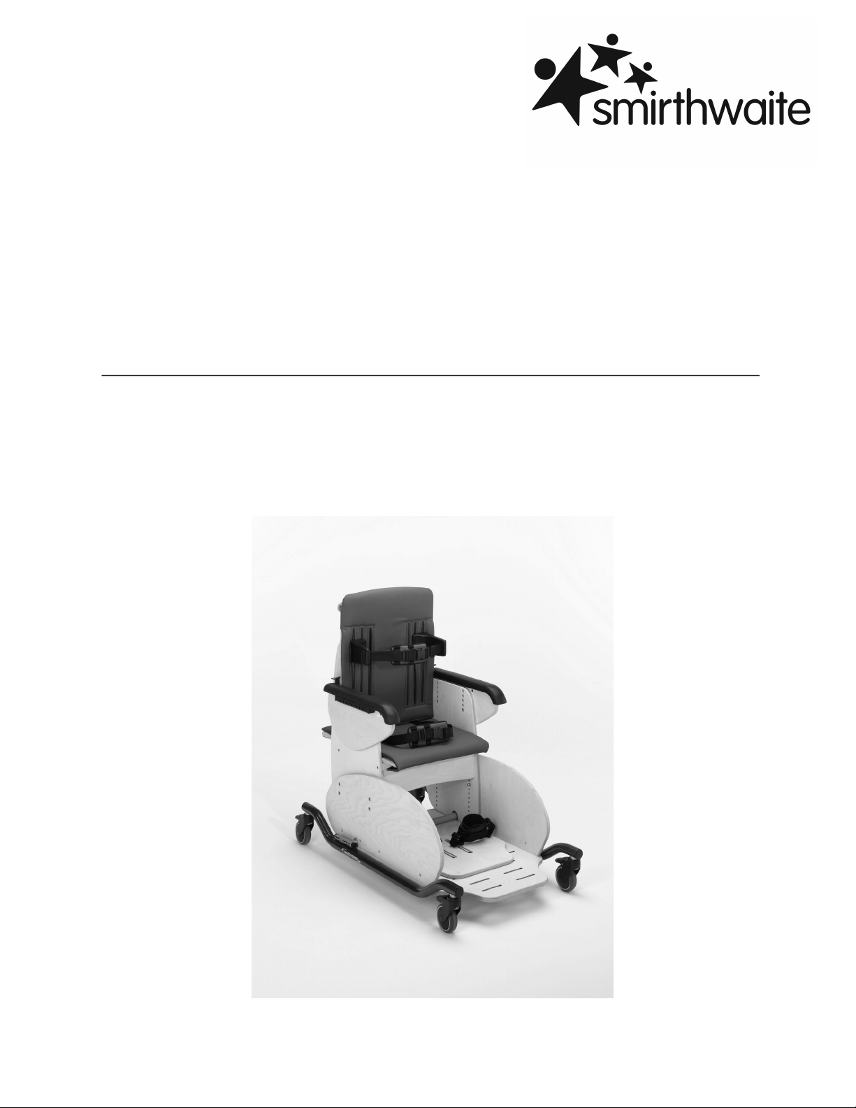
HARDROCK
INSTRUCTIONS FOR USE
Codes 8202-8204
Page 2
!
Hardrock
1
CONTENTS PAGE
1.0 INTRODUCTION 1
2.0 ILLUSTRATION & TECHNICAL DATA 2
3.0 FOR YOUR SAFETY 3
4.0 UNPACKING YOUR CHAIR 6
5.0 SETTING UP AND ADJUSTING YOUR CHAIR 7
6.0 CARE & MAINTENANCE 12
7.0 WARRANTY & SERVICE 16
8.0 CONTINOUS IMPROVEMENT 17
9.0 SERVICE INSPECTION 18
10.0 ANTI THRUST SYSTEM INSTRUCTIONS 20
INTRODUCTION
Thank you for choosing the Hardrock. It is an extremely durable, robust and stable chair
that has been specifically designed for children with complex learning difficulties and
children who are inclined to rock when seated.
It provides a moderate level of postural support and a safe and secure environment to
enable the children to engage in education, play and everyday activities necessary for
their development. It is suitable for use at home and in schools.
IMPORTANT!
These instructions should be read by all therapists and carers using
the equipment and should be retained for future reference. The
product should always be used under adult supervision.
Any incorrect use of the product and failure to follow the instructions
may put the user at risk or impede the function. If you have any
queries using this product or wish for further copies, please do not
hesitate to contact Customer Service department on
T: +44 (0) 1626 835552.
This product has been designed and manufactured specifically and
solely for use by clients with special needs.
Page 3
!
Hardrock
2
2.0 ILLUSTRATION OF YOUR CHAIR
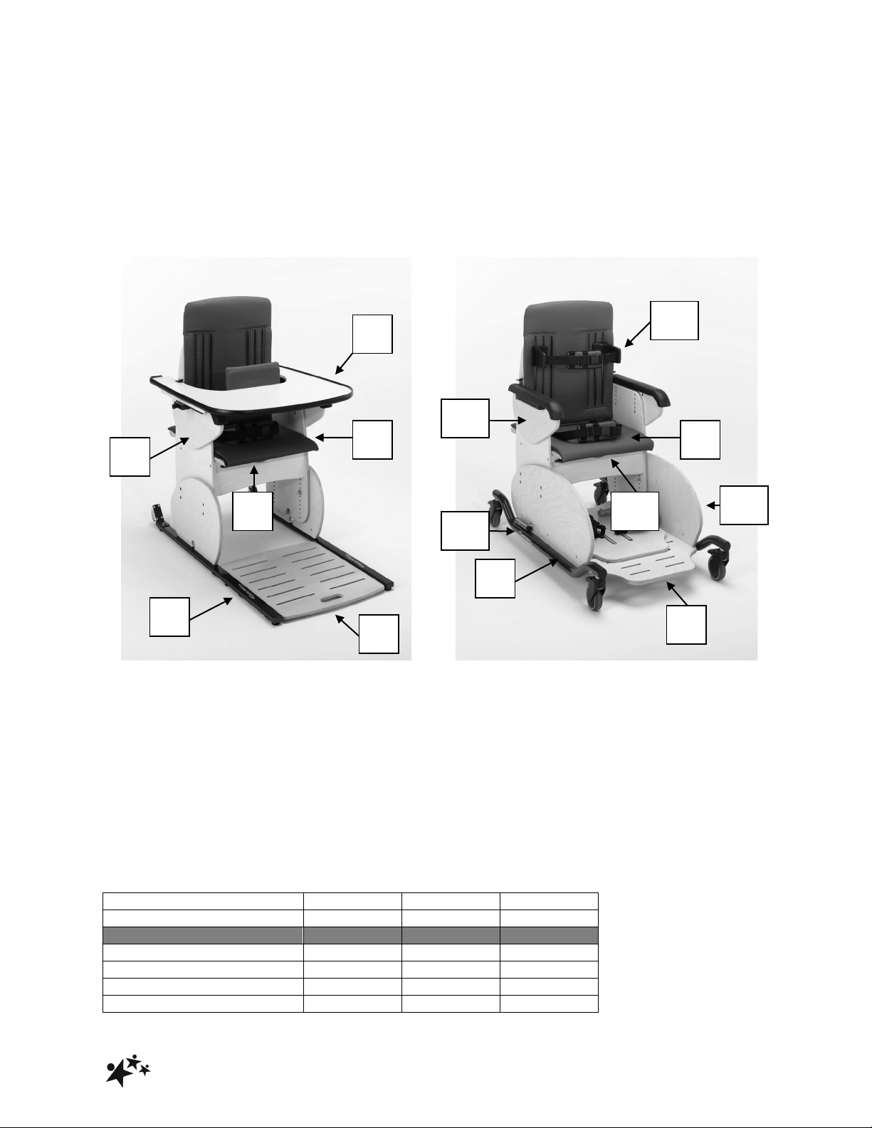
HARDROCK SIZE 2 & 3
Code 8202-8203!
HARDROCK SIZE 4
Code 8204!
1.Ski
2.Pelvic strap
3.Footboard
4.Anti-thrust cushion
5.Armrest
6.Tray Note: Size 4 also comes with tray as
standard (not shown)
2.1 TECHNICAL DATA
7.Mobile Base with lockable castors
8.Pelvic strap
9.Footboard
10.Anti-thrust cushion
11.Armrest
12.Extended gables (optional)
13.Stabilisers (optional)
14.Thoracic supports (optional)
SIZE 2 3
4
CODE
8202
8203
8204
Dimensions
Seat Height (mm)
270-410
290-430
375-525
Back Height (mm)
390
470
575
Width (mm)
350
430
470
Seat Depth (mm)
300-415
370-485
400-550
1 2 3
6
5
4
7 8 9
10
11
13
12
14
Page 4
!
Hardrock
3
User Weight (kg)
60
70
90
3.0 FOR YOUR SAFETY
STOP!
Please read these instructions CAREFULLY and THOROUGHLY.
• The user should NOT be left unattended whilst in the Hardrock. Always ensure a
responsible therapist or carer is in attendance.
• For the initial setting up of the Hardrock and at subsequent/future review of the child,
measurements of the child’s seat depth and height is required.
• The therapist should be familiar with the methods of adjustment and have completed
all adjustments appropriately to meet the needs of the child using the measurements
taken before transferring the child into the chair.
• Adjusting the seat height of the Hardrock is easier and safer if carried out by two
people.
• Ensure all castors on the mobile base are locked with castors facing inwards by
tilting the chair slightly onto its side before making any adjustments.
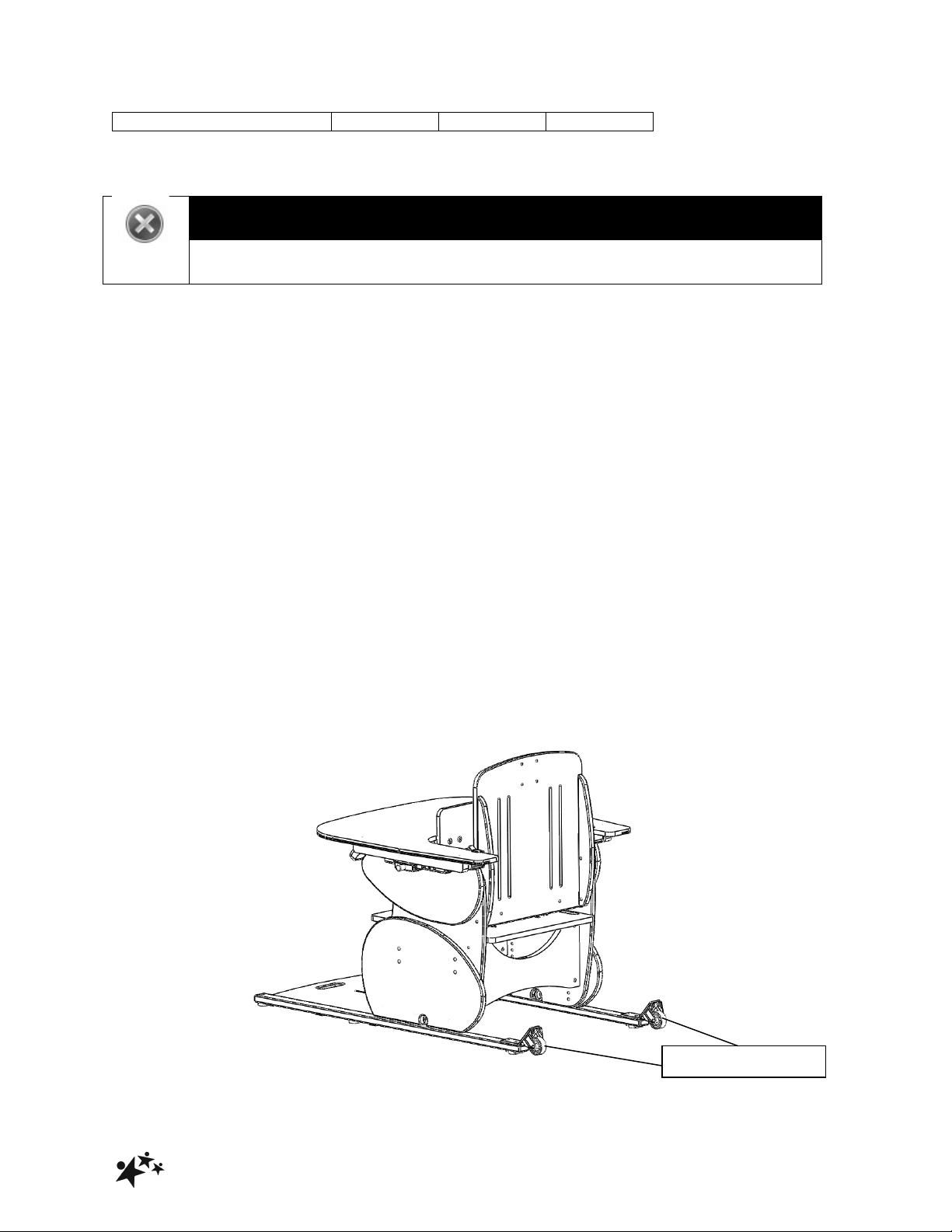
• Rear transporter wheels have been fitted onto the skis to facilitate moving the chair.
DO NOT use whilst the child is seated in the chair.
Rear transporter wheels
Page 5

!
Hardrock
4
If rear transporter wheels have not been fitted, Hardrock should only be moved by
two people.
• Only Hardrock fitted onto mobile base can be used as an indoor transit chair.
• The Hardrock castors are designed for indoor use only and may be damaged if used
outdoors.
• The Hardrock is only to be used on a flat level surface.
• DO NOT EXCEED MAXIMUM WEIGHT LIMITS SPECIFIED
• Regular maintenance checks and cleaning are essential for the safe use of this
equipment (see care and maintenance section).
• If any part is loose, damaged or functioning incorrectly, do not use until rectified.
• Always fasten the pelvic strap and any other straps provided.
• Regularly check that they are not showing any signs of tearing or fraying and that
they fasten correctly.
• Ensure that all nuts, bolts and handwheels are securely tightened and that none are
missing.
• Always keep this product away from naked flames, cigarettes and sources of heat
including open fireplaces, radiators, heaters etc.
• DO NOT fit parts or accessories of other manufacturers to this product unless
authorized to do so in writing by Smirthwaite Ltd. Failure to follow these instructions
will not only invalidate the guarantee but could make the chair dangerous to use.
Smirthwaite Ltd will not accept liability for any injury or damage incurred through
such malpractices. Any repairs required must be carried out by Smirthwaite Ltd
authorized personnel.
• The Hardrock is CE marked. This certifies that it meets all relevant European safety
requirements.
Page 6
!
Hardrock
5
STOP!
LAP STRAPS & HARNESSES SAFETY NOTICE
Lap straps and harnesses must be appropriate and safe for the user and
the users clothing.
Lap straps and harnesses must be checked every time the chair is used to
ensure they are fitted as prescribed by the clinician, take account of the
users clothing and are tightened so that the user cannot sustain injury.
Checking the fit of lap straps and harnesses must be done with the user in
the chair and should be undertaken as soon as the users sits in the chair.
STOP!
If you believe this product to be faulty – DO NOT USE – Contact
Smirthwaite Ltd on T: +44 (0) 1626 835552
Page 7

!
Hardrock
6
4.0 UNPACKING YOUR CHAIR
STOP!
If in any doubt, ALWAYS seek ADVICE.
Always turn hand wheels, levers and screws clockwise to tighten or
anti-clockwise to loosen.
• When delivered, the Hardrock will be supplied fully assembled except for the tray.
• Please take note of any instructions on the packaging/box when unpacking the chair.
• Once the chair has been carefully unpacked, please check all parts.
• If any part is loose, damaged or functioning incorrectly, do not use until rectified.
Should you wish to query any aspect of your product, please contact Smirthwaite
Customer Services on +44 (0) 1626 835 552 or [email protected]
Page 8
!
Hardrock
7
5.0 SETTING UP AND ADJUSTING YOUR CHAIR
STOP!
If in any doubt, ALWAYS seek ADVICE.
Always turn hand wheels, levers and screws clockwise to tighten or
anti-clockwise to loosen.
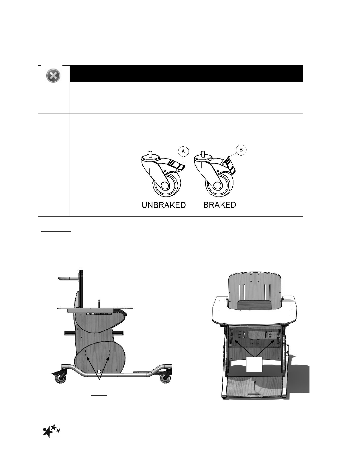
ALWAYS LOCK THE CASTORS WHEN ATTACHING ITEMS OR
MAKING ADJUSTMENTS. TO LOCK, APPLY FOOT TO POINT (A) TO
UNLOCK APPLY FOOT TO
POINT (B)
!
5.1 SEAT
5.1.1 SEAT AJUSTMENTS
Two adjustments can be made to the seat; height and depth.
A
B
Page 9
!
Hardrock
8
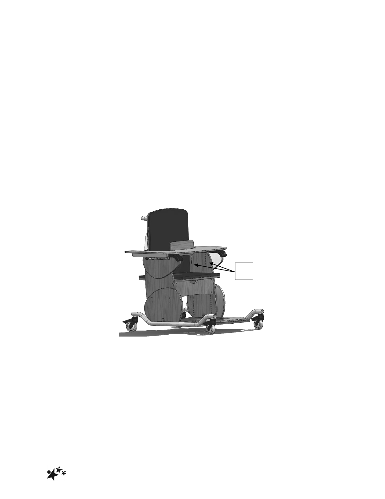
5.1.2 HEIGHT
• Lay the chair on its side. (2 people required)
• Remove the 4 hexagon head screws (A) on each side.
• With one person holding the top seat section of the chair, slide the seat section to the
required height.
• Replace the 8 screws.
• Ensure all 8 screws match each other equally in height holes.
• Tighten the screws.
• Return chair to upright position
5.1.3 DEPTH
• Lift the front edge of the seat pad attached with Velcro under the seat.
• Loosen the 4 hexagon screws (B) in the slots on the edge of the seat by a just a couple of
turns.
• Slide the seat back or forwards to desired depth.
• Tighten the screws.
5.2 ARMREST
• Loosen the 2 hexagon screws ( C )
• Position at required height using any of the holes available.
• Tighten the screws.
• Ensure that both armrests are set at the same height and horizontal.
C
Page 10
!
Hardrock
9
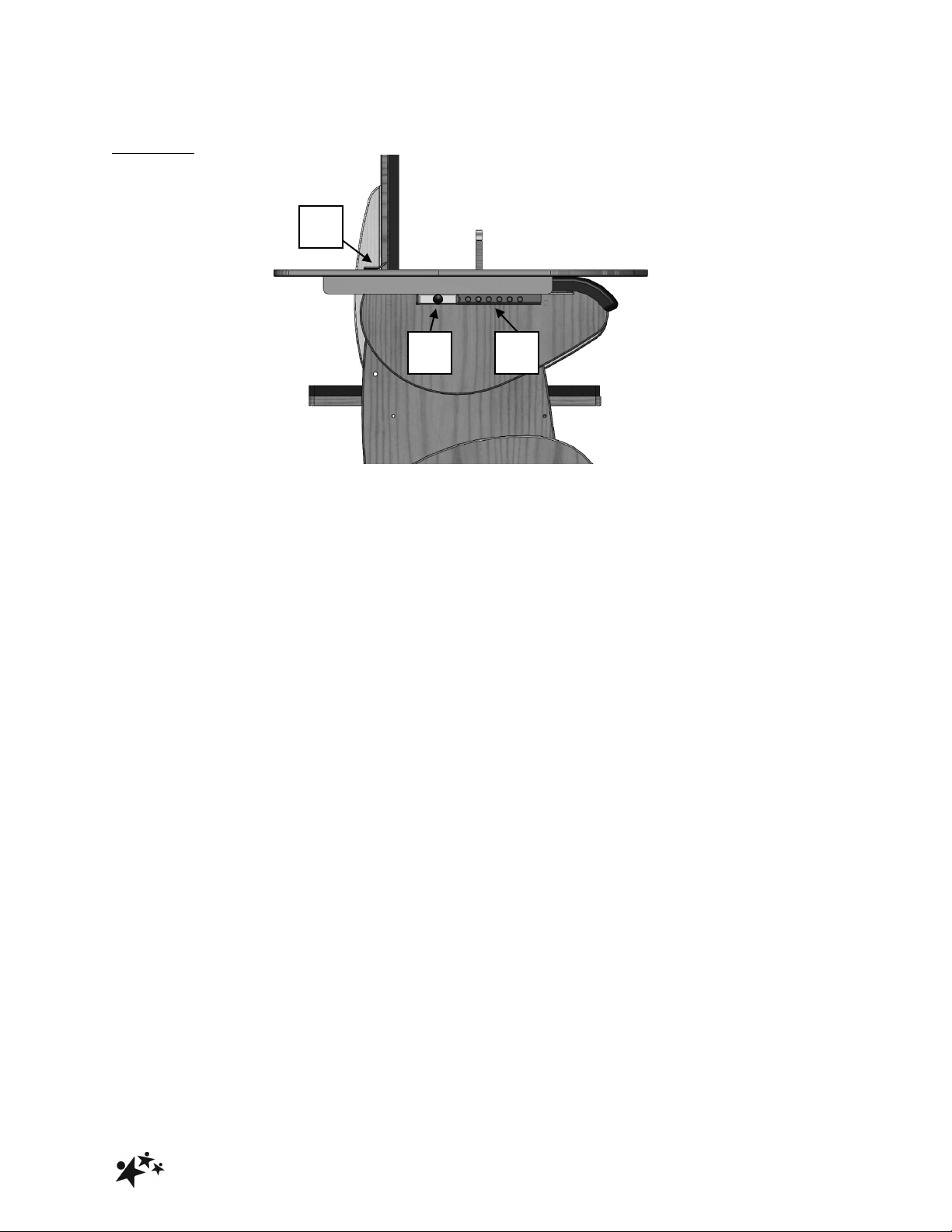
5.3 TRAY
• Hold the sides of the tray
• Pull 2 plunger pins (D) out to rest and park at an angle.
• Rest back of tray on armrest.
• Slide back of tray under the tray retainer (E) and then to desired position.
• Release pins securely into position in the holes along the armrest (F)
• Ensure chest pad is correctly positioned in front of child for safety, appropriate support and
reduce undesired movement.
D E F
Page 11
!
Hardrock
10
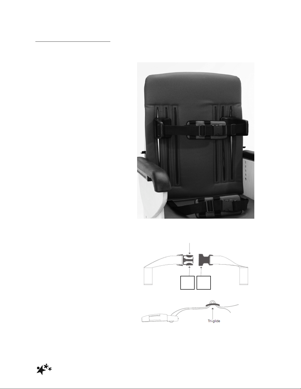
5.4 THORACIC SUPPORTS
Two adjustments can be made to the thoracic supports; size 3 upwards.
5.4.1 HEIGHT
To adjust:
• Loosen handwheels on rear of seat.
• Move the thoracic support up or
down to desired position.
• Re-tighten the handwheels.
5.4.2 WIDTH
To adjust:
• Loosen handwheels on rear of seat,
and remove from the vertical slots.
• Position the thoracic support
appropriate vertical slot for the
desired width.
• Re-tighten the handwheels.
5.5 STRAPS
• The buckle is secured by pushing
(G) into (H).
• To release the buckle, press both
sides of (G)
• The strap length can be altered by
adjusting the tri-glide (as shown
opposite)
G
H
Page 12
!
Hardrock
11
5.6 HEELSTOP FOR HEEL
HUGGY ACCESSORY
The heel stop can be adjusted in depth.
• Loosen the screws (I) by a couple
of turns.
• Slide it back or forwards to desired
depth.
• Re-tighten screws.
5.7 POMMEL
Pommels have to be specified at the
time of order. A pommel cannot be
retrofitted.
To adjust:
• Loosen hand wheel
• Position the pommel in or out to the
desired position.
• Re-tighten handwheels.
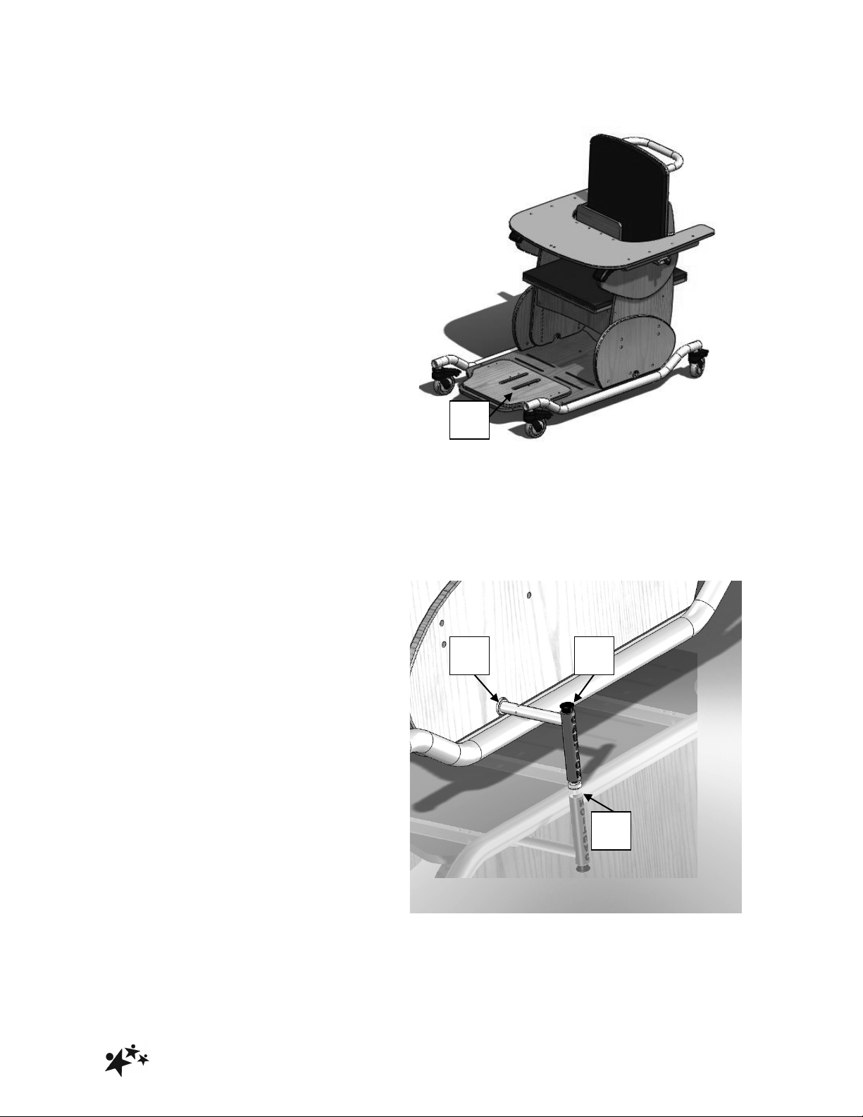
5.8 STABLISERS
Stabilisers can be ordered as an
accessory at time of order or retrofitted,
giving additional stability to the
Hardrock product.
5.8.1 Retrofitting
• Slacken side panel fixing screws
located under the chassis
• Insert stabilizers through the
‘mouse-hole’ (J) of the side panel.
• Turn the stabilizer to the vertical
position (as shown above).
• If needed, drill M8 clearance hole
through the baseboard
• Secure stabilizers with M8 cap
screws, nuts and washers.
• Re-tighten leg/side panel fixing
screws under the chassis
5.8.2 Extend stabilizer
• Depress button (K)
• Pull stander tube out (L)
• Release button.
• Turn it vertical to the ground - there
will be an audible click when
locked.
I J K
L
Page 13

!
Hardrock
12
6.0 CARE AND MAINTENANCE
IMPORTANT!
CLEANING IS RECOMMENDED ON A REGULAR BASIS
THE CLIENT SHOULD NOT BE SEATED IN THE CHAIR WHEN
CLEANING OR UNDERTAKING MAINTENANCE
All our wooden chairs are easy to clean. Each chair has anti-bacterial properties
ensuring that surfaces are kept hygienic to reduce any risk of cross infection.
• Clean upholstery and wooden parts with a damp cloth and mild detergent.
• Stubborn marks on the woodwork should be cleaned by using a soft brush.
• Do not soak or immerse the chair in water.
• The pelvic strap can be cleaned with a damp cloth. In cases of extreme soiling it
can be machined washed at low temperature with mild detergent but must be
drip dried.
• Store the chair in a cool dry place out of direct sunlight.
• DO NOT use bleach, solvents, abrasives, synthetic detergents, wax polishes,
antibacterial sprays or wipes.
• For further information please refer to MHRA or your NHS cleaning guidelines.
6.1 DAILY CHECKS
• Check the product for damage or loose components.
• Check all upholstery for signs of wear and tear.
• Check the straps for signs of wear and tear.
• Check the castors are running freely and brakes are in working order
6.2 MONTHLY CHECKS
• Repeat daily checks.
• Check all mechanical movements operate fully.
• Check the structure of the product for signs of damage, wear and tear.
6.3 ANNUAL SERVICE
The Hardrock chair should be serviced annually. Servicing must only be undertaken by
a Smirthwaite service engineer, or by a Smirthwaite trained representative.
Page 14

!
Hardrock
13
6.4 NOMINAL SERVICE LIFE
Your product has a nominal service life of 7 years, during which full post-sales support
will be available with regard to spares and servicing.
Product service life has been determined based upon the design complexity of product,
and the anticipated exposure to normal use.
Good practice dictates all Smirthwaite products have been designed and manufactured
to high levels of safety and quality, and will meet requirements of normal use when
maintained in line with our servicing recommendations.
STOP!
If the product has been out of use for an extended period of time (6
months or more) it should always be serviced prior to being
reissued.
If the product has been subjected to ‘heavy’ or ‘constant’ use, the
service should be reduced to half the recommended period.
Constant and/or heavy use is considered to be:
• Daily use above 7 hours duration
• Weekly use above 5 days duration
• Monthly use above 10 months per year
• Use by a client who is at 90% to 100% of the maximum weight limit of
the product. The maximum weight limit must NEVER be exceeded
• Use by a client who is extremely active, either voluntarily or
involuntarily
Page 15

!
Hardrock
14
6.5 EXTENDING NOMINAL SERVICE LIFE
At Smirthwaite we are proud to produce products that have a reputation for quality and
durability.
We believe our products have the potential to provide benefits to our clients beyond the
nominal service life documented above.
We will continue to provide full support beyond the nominal service life provided the
following conditions are met:
1. A full service schedule has been maintained.
2. A full service and inspection is undertaken at the end of the nominal service life
period
3. The product is subsequently serviced annually (or biannually if under
‘heavy/constant’ use conditions)
4. Smirthwaite reserve the right to limit support where parts/components are no
longer available
6.6 DOCUMENTATION/RECORDS
• It is the responsibility of the current equipment owner to ensure the ‘Instructions for
Use’ manual and any further manuals for accessories fitted to the equipment are
handed over to the new owner at the time of exchange/sale
• It is the responsibility of the current equipment owner to ensure the service and
inspection record form is kept up to date
6.7 PRODUCT CONFIGURATION
• Smirthwaite will document and maintain a record of the original product configuration
at the time of first sale
• Smirthwaite will not be held responsible for any subsequent changes to this
configuration unless authorized to do so in writing by Smirthwaite Ltd
• It is the equipment owner’s responsibility to maintain their own records of changes to
the equipment configuration and to be able to provide such records to subsequent
owners to maintain traceability
Page 16
!
Hardrock
15
• We recommend an inspection/service by a Smirthwaite Service Engineer (or
Smirthwaite trained engineer) whenever a significant change is made to product
configuration to ensure the product is safe to use. If in any doubt, ALWAYS seek
ADVICE
IMPORTANT REMINDER!
DO NOT fit parts or accessories of other manufacturers to this product
unless authorized to do so in writing by Smirthwaite Ltd.
Any servicing or repairs required must be carried out by Smirthwaite Ltd
(or a Smirthwaite trained engineer).
If you believe this product to be faulty – DO NOT USE – Contact
Smirthwaite Ltd on T: +44 (0) 1626 835552
If in any doubt, ALWAYS seek ADVICE.
Page 17

!
Hardrock
16
7.0 WARRANTY & SERVICE
Smirthwaite warrants the products detailed on your order to be free from defects in
materials and workmanship for a period of 2 years from date of delivery. If a fault
develops during the period, please call Customer Services by email or telephone 01626
835552 who will advise you on the best course of action. Possible action may be for us
to arrange to send out one of our Service Engineers, or have the goods returned to us.
Should a repair not be possible within the guarantee period we will replace the product
for new or nearest equivalent product. In the unlikely event that we cannot repair or
exchange we will refund in full. This guarantee is for the UK only. The warranty
excludes faults due to accident, neglect, misuse, not following the Instructions and
normal wear and tear. This guarantee is in addition to your legal rights. Goods will only
be collected from the original delivery address.
A charge may be made where the goods cannot be repaired under the terms of the
warranty. You will be advised before this is made.
T: +44 (0)1626 835552 E: [email protected]
Page 18

!
Hardrock
17
8.0 CONTINUOUS IMPROVEMENT
Smirthwaite Ltd warrants the products detailed on your order to be free from defects in
materials and workmanship for a period of 2 years from date of delivery. If a fault
develops during the period, please call Customer Services by email or telephone 01626
835552 who will advise you on the best course of action. Possible action may be for us
to arrange to send out one of our Service Engineers, or have the goods returned to us.
Should a repair not be possible within the guarantee period we will replace the product
for new or nearest equivalent product. In the unlikely event that we cannot repair or
exchange we will refund in full.
This warranty is for the UK only. The warranty excludes faults due to accident, neglect,
misuse, not following the Instructions and normal wear and tear. This warranty is in
addition to your legal rights. Goods will only be collected from the original delivery
address.
A charge may be made where the goods cannot be repaired under the terms of the
warranty. You will be advised before this is made.
T: +44 (0)1626 835552 E: [email protected]
Page 19
!
Hardrock
18
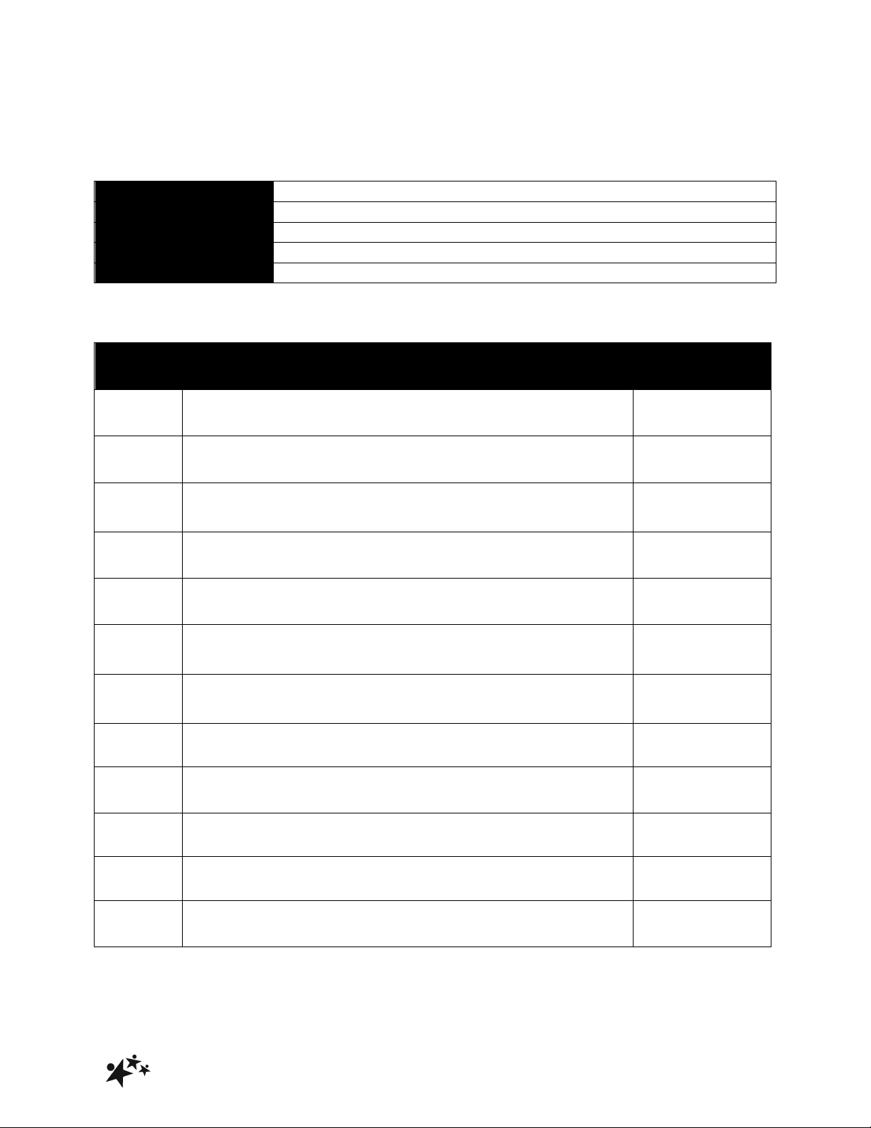
9.0 SERVICE INSPECTION
9.1 Product Information
Model
Size
Date of Manufacture
Serial Number
Final Inspection
9.2 Service & inspection record form:
Date
Procedure
Service
Personnel
Page 20

!
Hardrock
19
Page 21

!
Hardrock
20
ANTI THRUST
CUSHION
INSTRUCTIONS FOR USE
Page 22
!
Hardrock
21
1. ANTI – THRUST SYSTEM
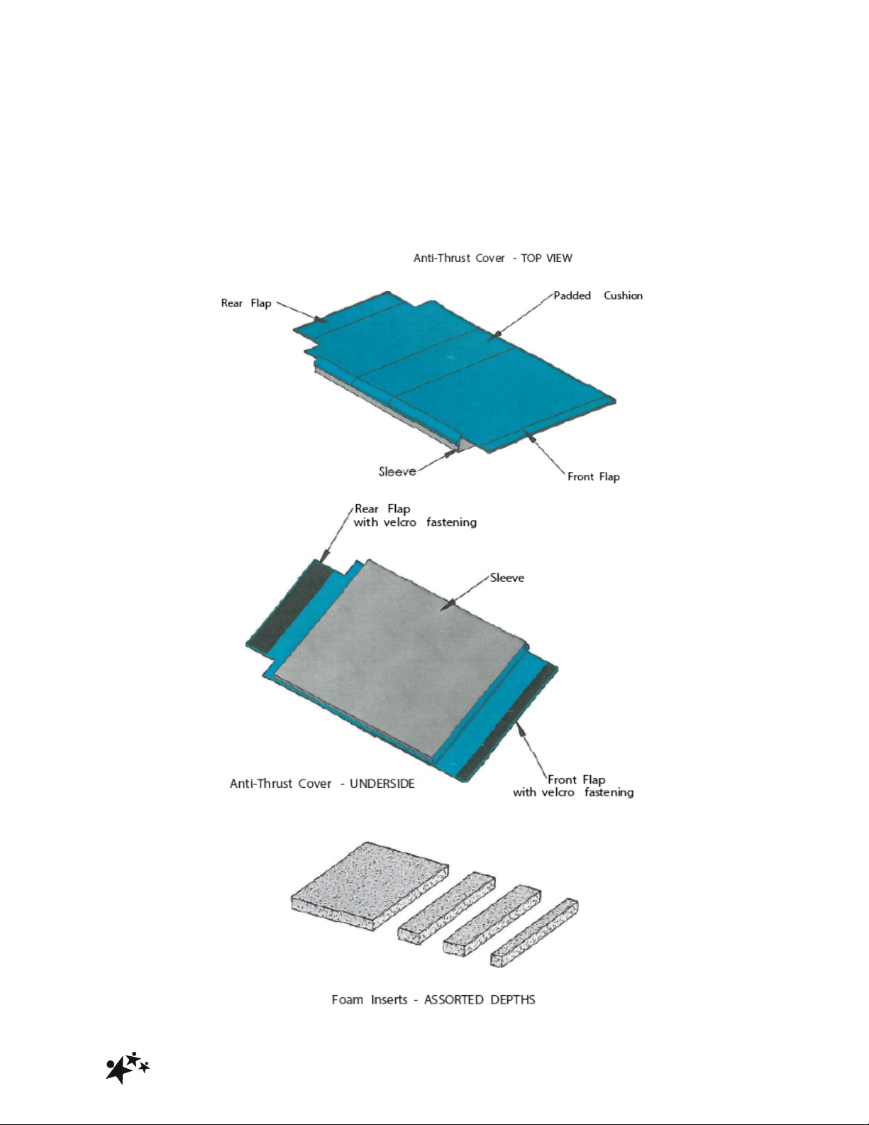
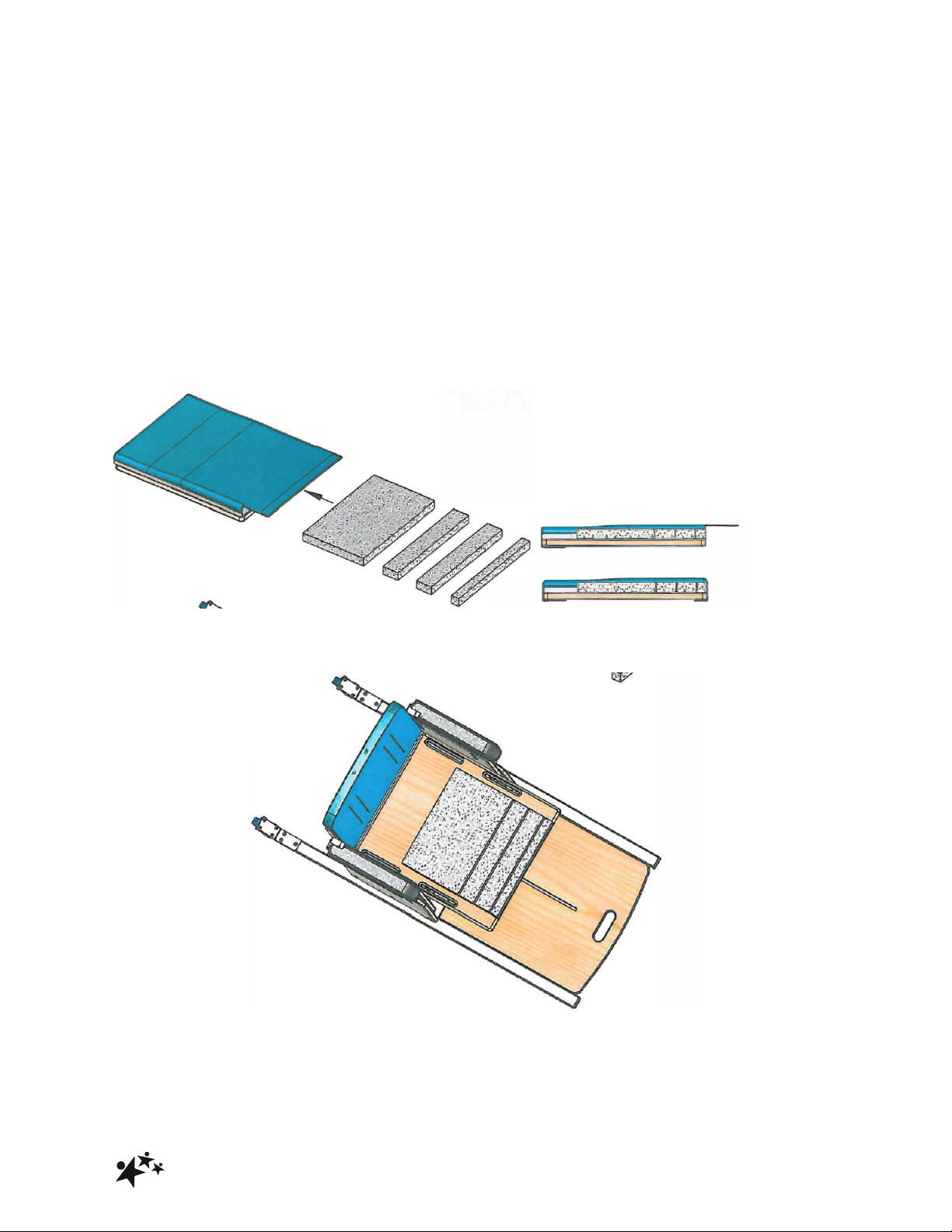
Anti-thrust system consists of;
1. Seat cover with velcro fastenings
2. Foam inserts of assorted depths
1.
2.
Page 23
!
Hardrock
22
2. SETTING UP THE SYSTEM
With the pelvis in an upright position against the back of the chair, there should be a
25mm gap between the back of the knee, in line with the front edge of the seat. Adjust
seat accordingly by loosening the hexagonal crews on top of the plywood seat, sliding
the seat to the required position, and then retightening the screws.
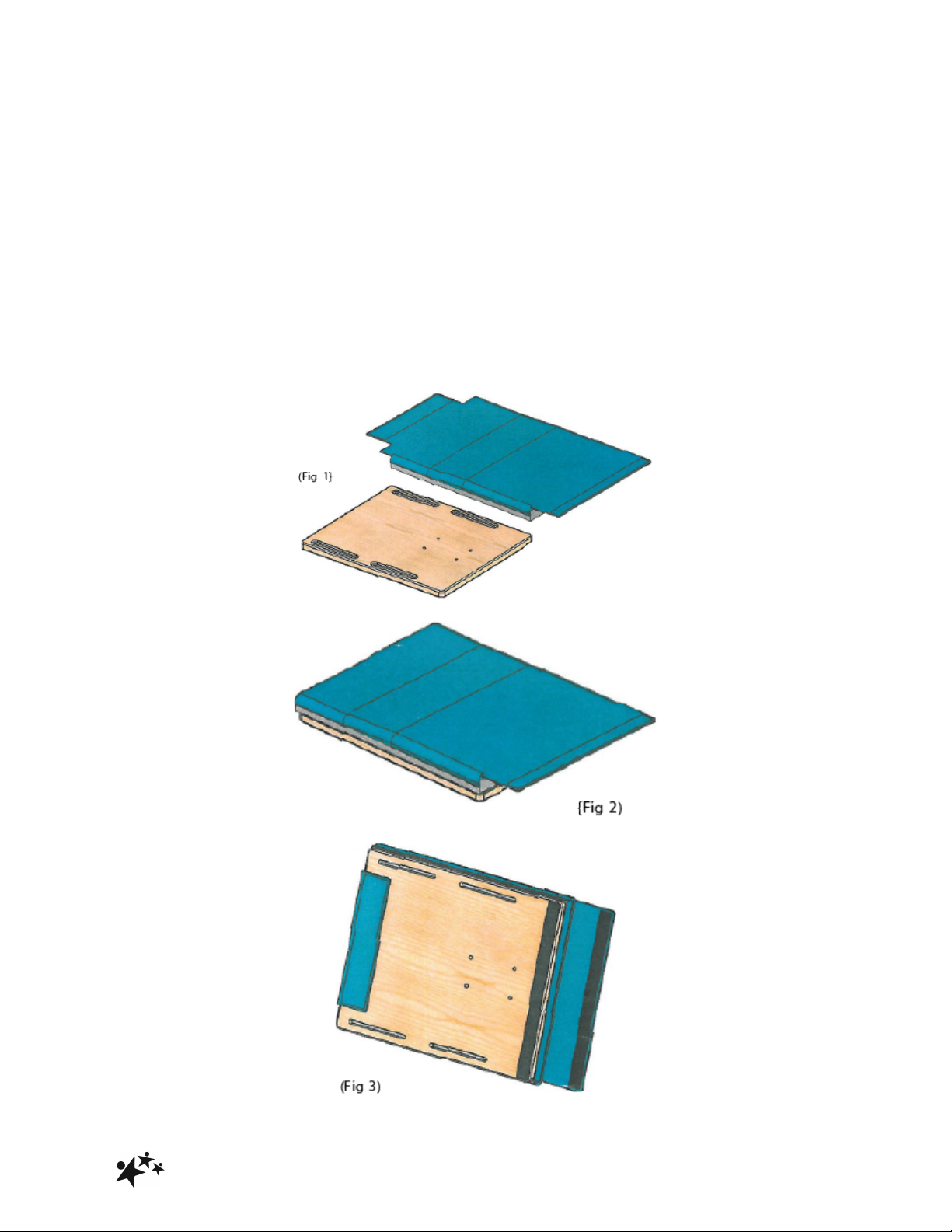
Fig 1 shows the anti-thrust cover and the plywood chair seat. With the seat firmly fixed
in place on the chair, position the cover on the seat as shown in Fig 2 and bend the
back flap around and under the back of the seat, fastening it with the Velcro fastenings.
Fig 3 shows the underside of the seat and cover, with the back flap
fastened tightly in place. Leave the front flap open at this stage as the foam strips will be
inserted here.
Page 24
!
Hardrock
23
Page 25
!
Hardrock
24
3. CORRECT PLACEMENT
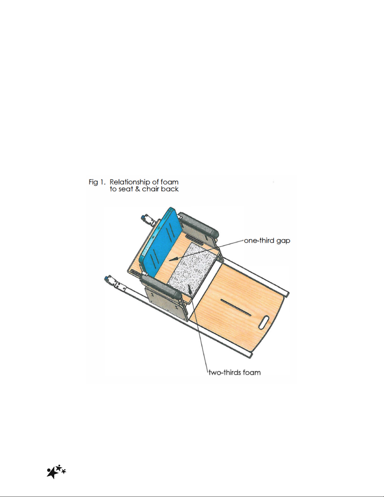
Fig 1 shows the relationship of the foam to the seat and chair back once it has been
inserted inside the Anti-Thrust Cover.
To create the required Anti-Thrust System, the femoral length (distance between the
front of the seat and the chair back upholstery) should be made up of approximately
two-thirds foam followed by a one- third gap as indicated.
At the smallest seat depth setting, the largest piece of foam is used. On the smallest
chair it may be necessary to substitute the large piece of foam with smaller pieces to
maintain the two-thirds/one third relationship.
Note: Fig 1 represents a guide to the position of the foam only. The foam must be
placed inside the Anti-Thrust Cover sleeve.
Page 26
!
Hardrock
25
As the femoral length increases, the seat depth must be increased accordingly by
loosening the screw on top of the plywood seat, adjusting the seat forward to the
required position, and then retightening the hexagonal screws. When the seat is
adjusted forward for extra seat depth, additional foam is added in any permutation
necessary to maintain the two-thirds foam/one third gap relationship (the example on
this page shows the seat at maximum depth using all 4 foams).
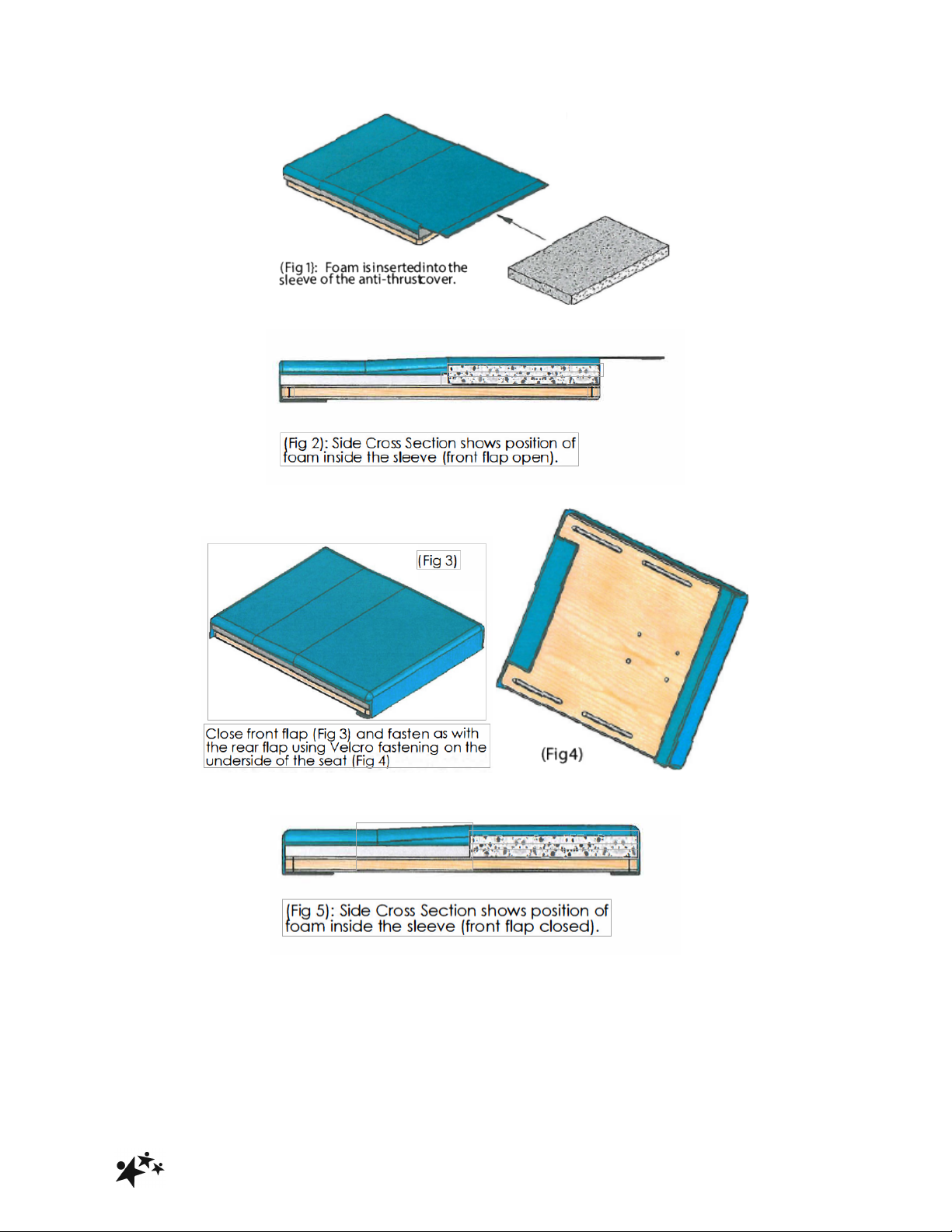
Keeping the Anti-Thrust Cover in place, loosen the front velcro fastening. Now push the
large piece of foam back to create the one-third gap between the rear of the foam and
the chair back cushion. Insert additional foam into the sleeve as required to fill the front
two-thirds of the cover.
Page 27

!
Hardrock
26
Page 28

!
Hardrock
27
Smirthwaite, 16 Wentworth Road, Heathfield, Newton Abbot, Devon.TQ12 6TL
T: +44 (0) 1626 835552 F: +44 (0) 1626 835428 E: [email protected] www.smirthwaite.co.uk
 Loading...