

Page 1
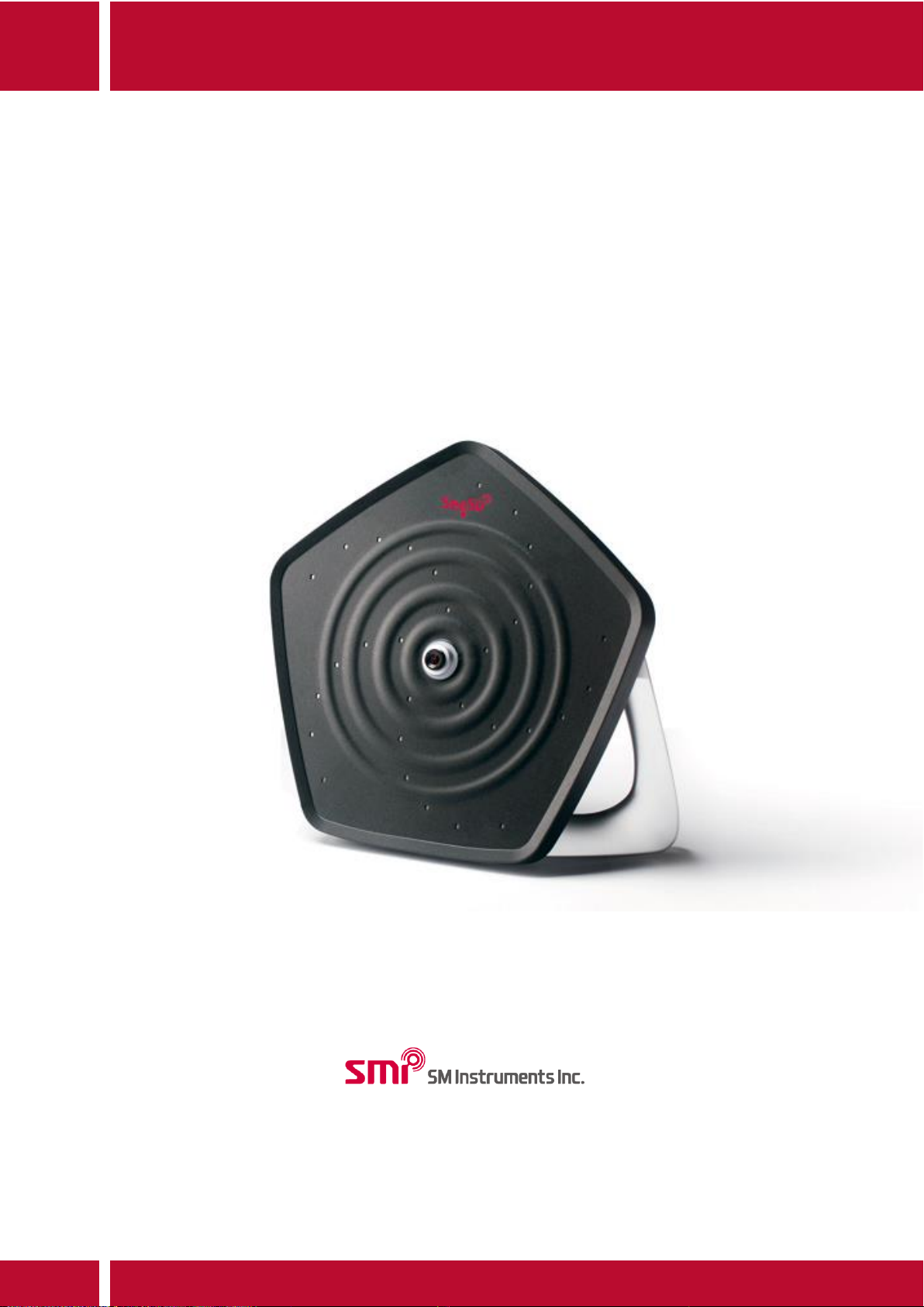
SeeSV-S205W User's Manual
Page 2
SeeSV-S205 User's Manual
Rev: 1.4.0
Doc. Type: User Manual 1 SM Instruments Co., Ltd.
1 Contents
1 Contents ........................................................................................................................................................................................................... 1
2 Introduction of System ............................................................................................................................................................................. 3
2.1 Components of System ................................................................................................................................................................. 3
3 Hardware Installation................................................................................................................................................................................. 4
3.1 Hardware Installation ..................................................................................................................................................................... 4
3.2 Status of Sound Camera Lamp.................................................................................................................................................. 7
4 Software Installation .................................................................................................................................................................................. 8
4.1 Sound Camera Software Installation ...................................................................................................................................... 8
4.2 Sound Camera Software Activation ..................................................................................................................................... 13
4.3 IP Config ............................................................................................................................................................................................ 15
5 Software Functions .................................................................................................................................................................................. 17
5.1 Software Mode ............................................................................................................................................................................... 17
5.2 Control Buttons .............................................................................................................................................................................. 18
5.3 Sound Camera Image ................................................................................................................................................................. 18
5.4 Image Threshold ............................................................................................................................................................................ 19
5.5 Image Range ................................................................................................................................................................................... 19
5.6 Image Average ............................................................................................................................................................................... 19
5.7 Signal Graphs .................................................................................................................................................................................. 20
5.7.1 Time Signal of Microphone ....................................................................................................................................... 20
5.7.2 Power Spectrum of Microphone ............................................................................................................................. 21
5.7.3 Level Trend of Beampower ......................................................................................................................................... 21
5.7.4 1/3 Octave Level of Microphone ............................................................................................................................ 21
5.8 Band Pass Filter .............................................................................................................................................................................. 22
5.9 Graph Selector ................................................................................................................................................................................ 22
5.10 Device Status Lamp .................................................................................................................................................................. 22
5.11 Setup ............................................................................................................................................................................................... 22
5.11.1 Data Folder ................................................................................................................................................................... 23
5.11.2 Open Data Folder ...................................................................................................................................................... 23
5.11.3 Prefix of Filename ...................................................................................................................................................... 23
5.11.4 Record Type .................................................................................................................................................................. 23
5.11.5 Trigger Level ................................................................................................................................................................. 24
5.11.6 Duration ......................................................................................................................................................................... 24
5.11.7 Product Type ................................................................................................................................................................ 25
Page 3
SeeSV-S205 User's Manual
Rev: 1.4.0
Doc. Type: User Manual 2 SM Instruments Co., Ltd.
5.11.8 Mic Gain ......................................................................................................................................................................... 25
5.11.9 Mic Channel ................................................................................................................................................................. 25
5.11.10 Max/Min Level ............................................................................................................................................................. 25
5.11.11 Overlay Mode .............................................................................................................................................................. 26
5.11.12 Transparency ................................................................................................................................................................ 26
5.11.13 Mirror Mode ................................................................................................................................................................. 26
5.11.14 Image Calibration…………………………………………………………………………………………………………………...29
5.11.15 Recording Advanced Setup……………………………………………………………………………………………………29
6 Software shortcut keys .......................................................................................................................................................................... 28
7 Maintenance and Troubleshooting .................................................................................................................................................. 29
7.1 Sound Camera Firmware Update .......................................................................................................................................... 29
7.1.1 How to update Sound Camera Firmware ........................................................................................................... 29
7.2 Modify the focus of sound camera ……………………………………………………………………………………………………32
7.2.1 How to modify the focus of sound camera ……………………………………………………………………………..32
7.3 Modify the position of overlay image…………………………………………………………………………………………………33
7.3.1 How to modify the position of overlay image ………………………………………………………………………33
8 Specifications .............................................................................................................................................................................................. 34
9 Caution ………………………………………………………………………………………………………………………………………………………..35
Page 4
SeeSV-S205 User's Manual
Rev: 1.4.0
Doc. Type: User Manual 3 SM Instruments Co., Ltd.
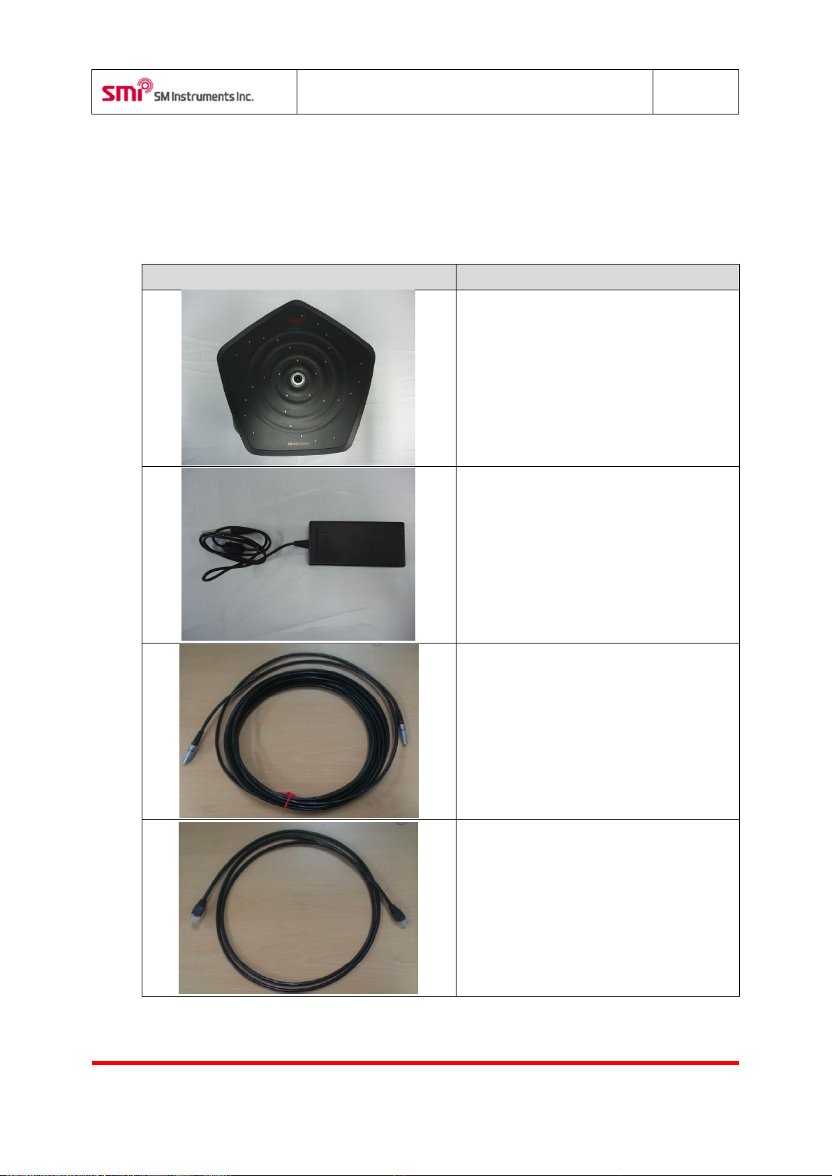
Item
Description
Portable sound camera.
AC/DC Power Adaptor
LEMO to LEMO Cable.(10m)
RJ45 LAN Cable.(1m)
2 Introduction of System
2.1 Components of System
Page 5
SeeSV-S205 User's Manual
Rev: 1.4.0
Doc. Type: User Manual 4 SM Instruments Co., Ltd.
Status
Description
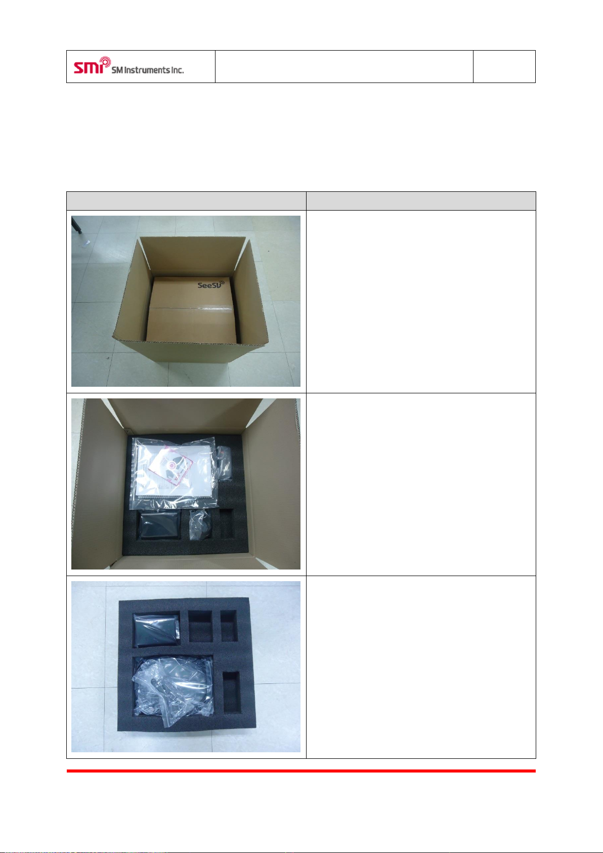
Open the outer box.
Open the inner box.
- SeeSV-S205W Manual.
- SeeSV-S205W Quick Manual.
- SeeSV-S205W Install CD
Take the cables out.
- LEMO to LEMO cable.
- RJ45 LAN cable
- POE Controller
3 Hardware Installation
3.1 Hardware Installation
Page 6
SeeSV-S205 User's Manual
Rev: 1.4.0
Doc. Type: User Manual 5 SM Instruments Co., Ltd.
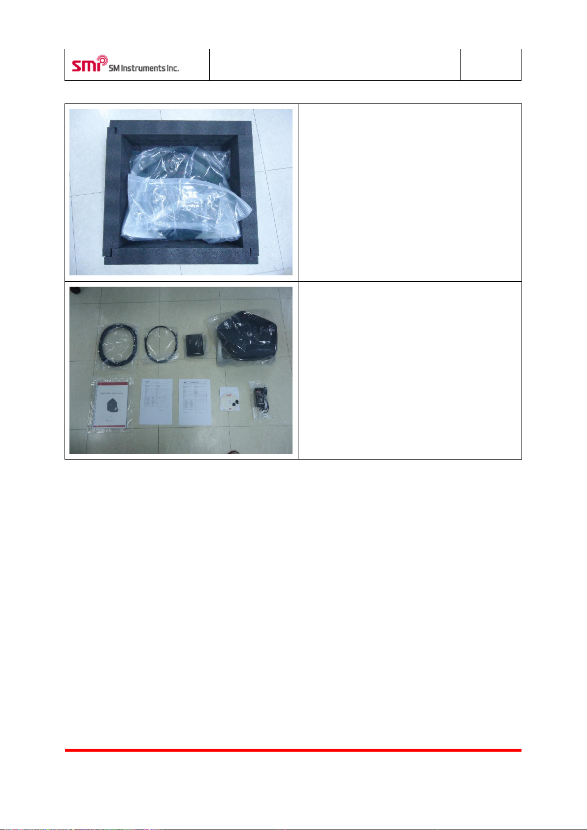
Take out the sound camera.
Main components of the system are shown here.
Page 7
SeeSV-S205 User's Manual
Rev: 1.4.0
Doc. Type: User Manual 6 SM Instruments Co., Ltd.
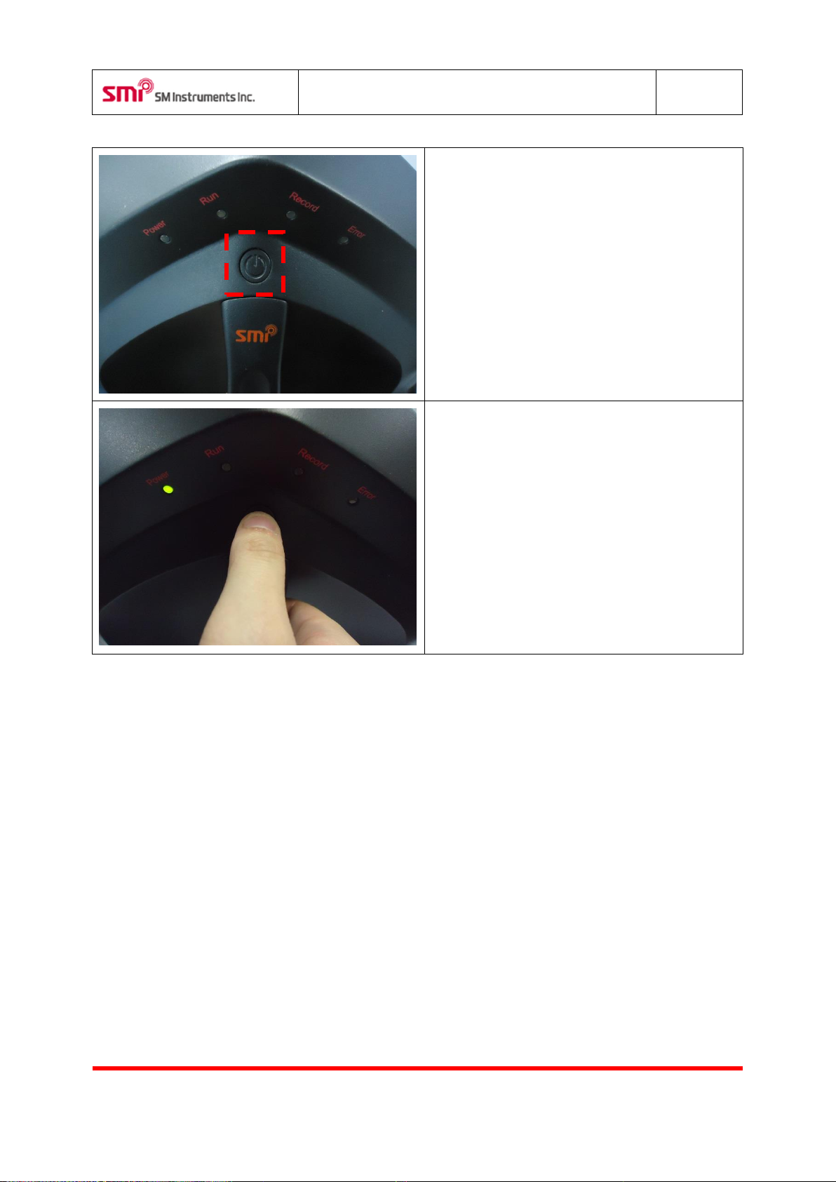
Power switch.
The power is turned on, press the button for 3
seconds.
Page 8
SeeSV-S205 User's Manual
Rev: 1.4.0
Doc. Type: User Manual 7 SM Instruments Co., Ltd.
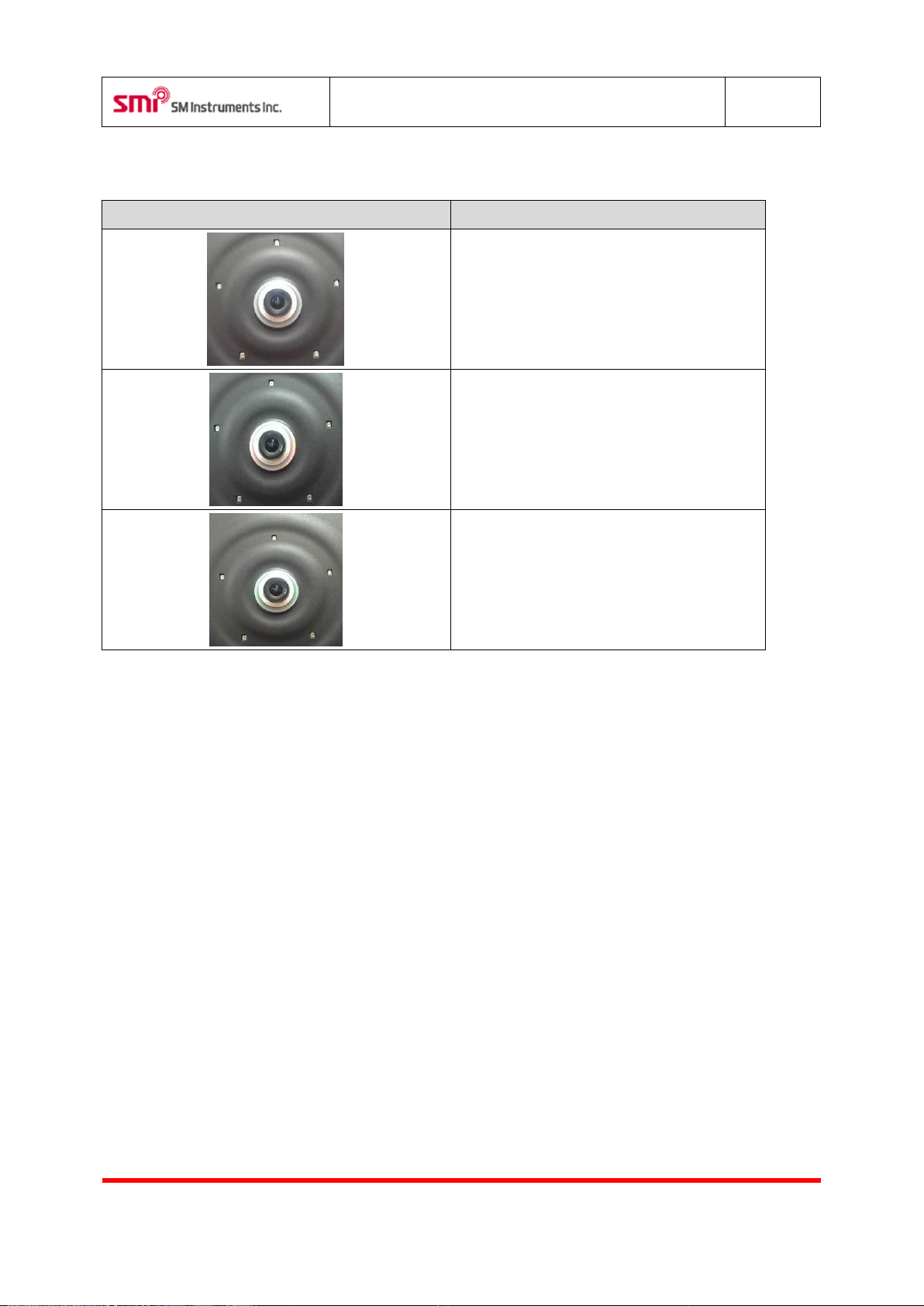
Status
Description
Not powered.
Initializing (orange).
Sound camera is ready to use (green).
3.2 Status of Sound Camera Lamp
Page 9
SeeSV-S205 User's Manual
Rev: 1.4.0
Doc. Type: User Manual 8 SM Instruments Co., Ltd.
Item
Description
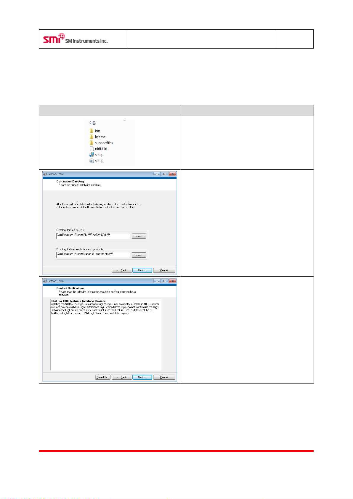
Run “Setup.exe”.
Confirm destination directory and click “Next>>”.
Read Product Notifications and click “Next>>”.
4 Software Installation
4.1 Sound Camera Software Installation
Page 10
SeeSV-S205 User's Manual
Rev: 1.4.0
Doc. Type: User Manual 9 SM Instruments Co., Ltd.
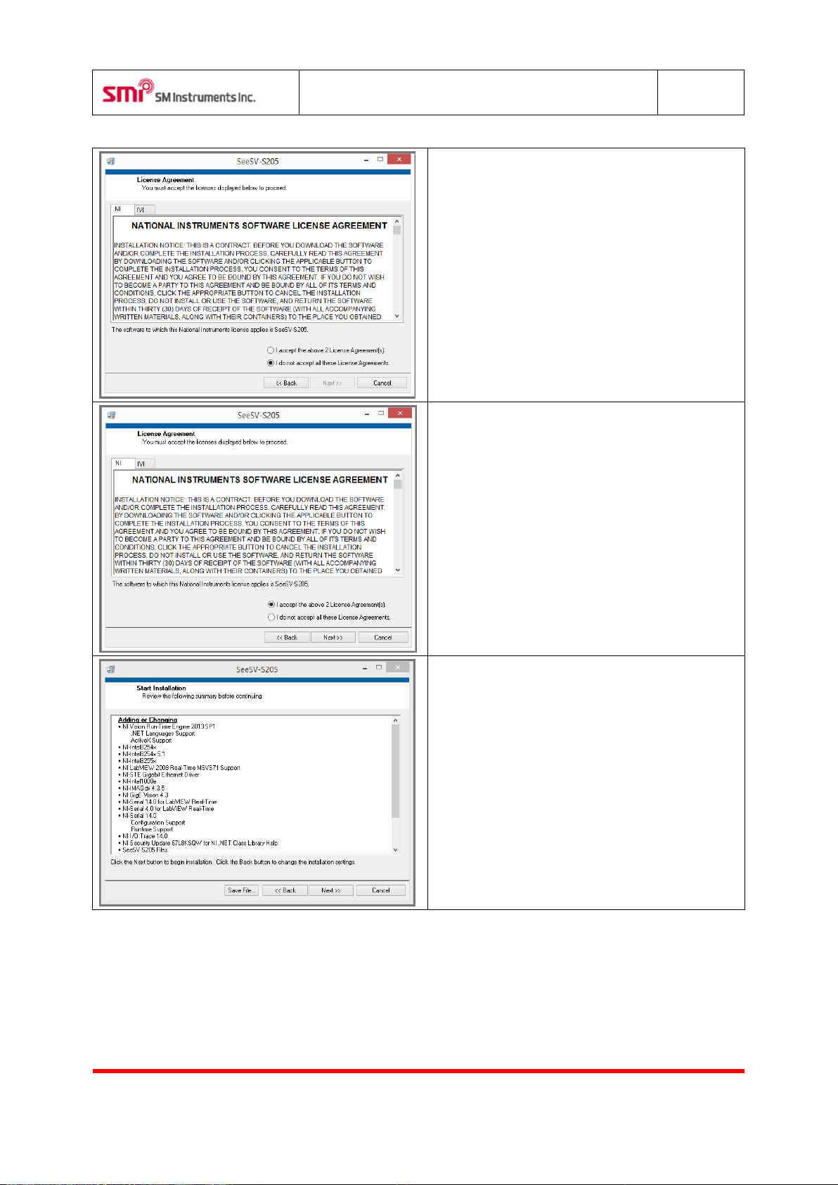
Read license agreement.
Check “I accept the above 2 License Agreements”
and click “Next>>”.
Confirm items for installing and click “Next>>”.
Page 11
SeeSV-S205 User's Manual
Rev: 1.4.0
Doc. Type: User Manual
10
SM Instruments Co., Ltd.
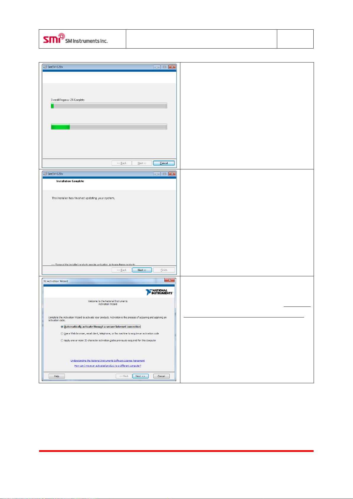
Installation is proceeding.
Installation is complete. Click “Next>>”.
The NI vision run-time engine should be activated.
Connect PC to the internet and select "Automatic-
ally activate through a secure Internet connection".
Click “Next>>”.
Page 12
SeeSV-S205 User's Manual
Rev: 1.4.0
Doc. Type: User Manual
11
SM Instruments Co., Ltd.
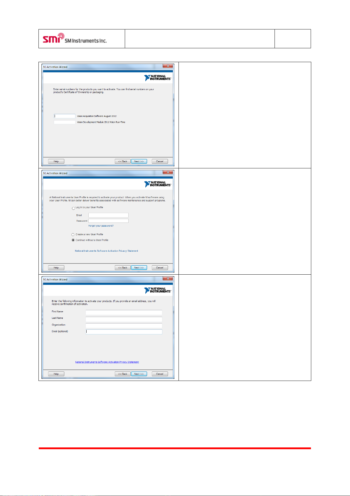
Input the serial number of NI Vision Run-Time
Engine in both boxes.
For members of “www.ni.com”, select “User Profile
Login”. In this, “Continue without a User Profile" is
screenshot shown.
Input end user information.
Page 13
SeeSV-S205 User's Manual
Rev: 1.4.0
Doc. Type: User Manual
12
SM Instruments Co., Ltd.
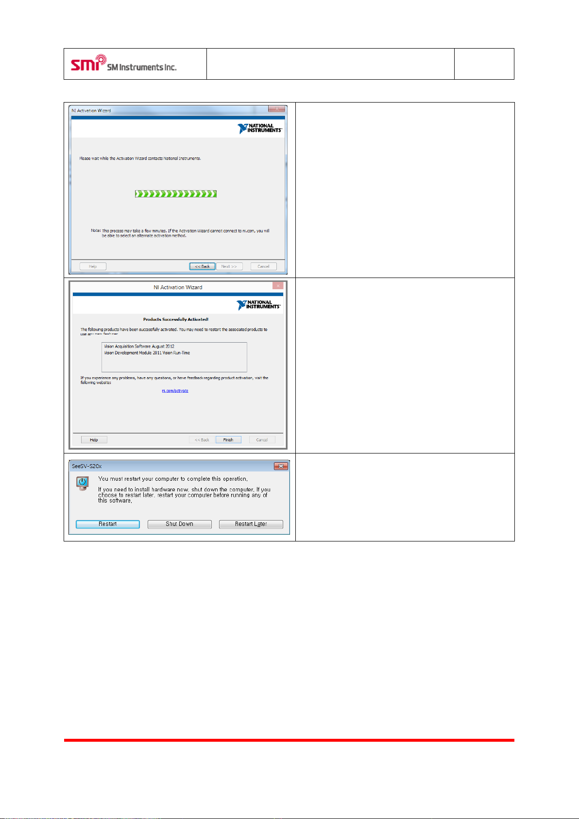
Activation is in process.
The NI vision run-time engine is successfully
activated. Click “Finish”.
If this is the first time to install the software, you
will be requested to restart the PC. Click “Restart”.
Software installation is complete.
Page 14
SeeSV-S205 User's Manual
Rev: 1.4.0
Doc. Type: User Manual
13
SM Instruments Co., Ltd.
Item
Description
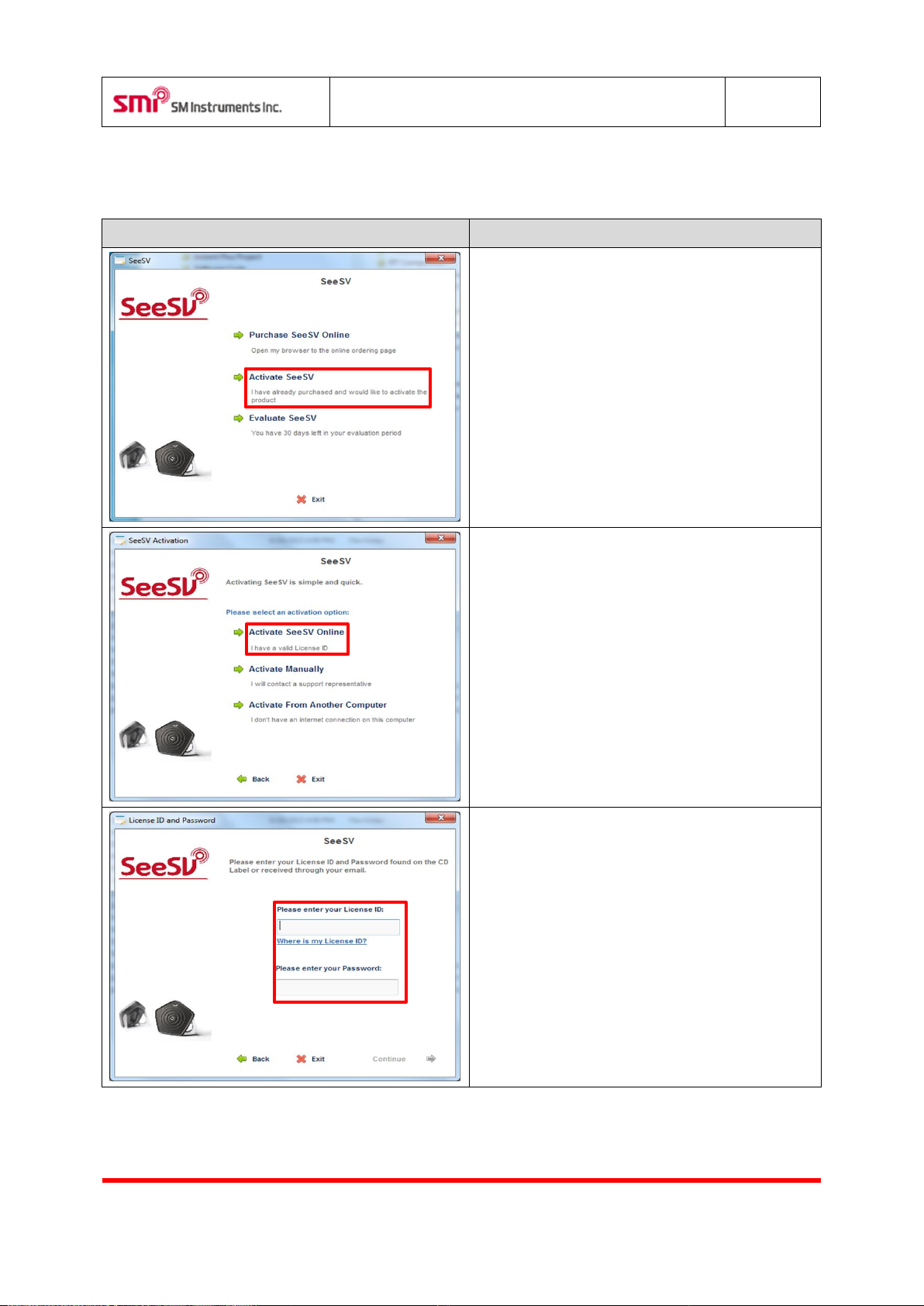
If the software is being installed for the first time,
the software license confirmation window will
appear.
Click the “Activate SeeSV”.
Click the “Activate SeeSV Online”.
Input to License ID & password in text box.
4.2 Sound Camera Software Activation
Page 15
SeeSV-S205 User's Manual
Rev: 1.4.0
Doc. Type: User Manual
14
SM Instruments Co., Ltd.
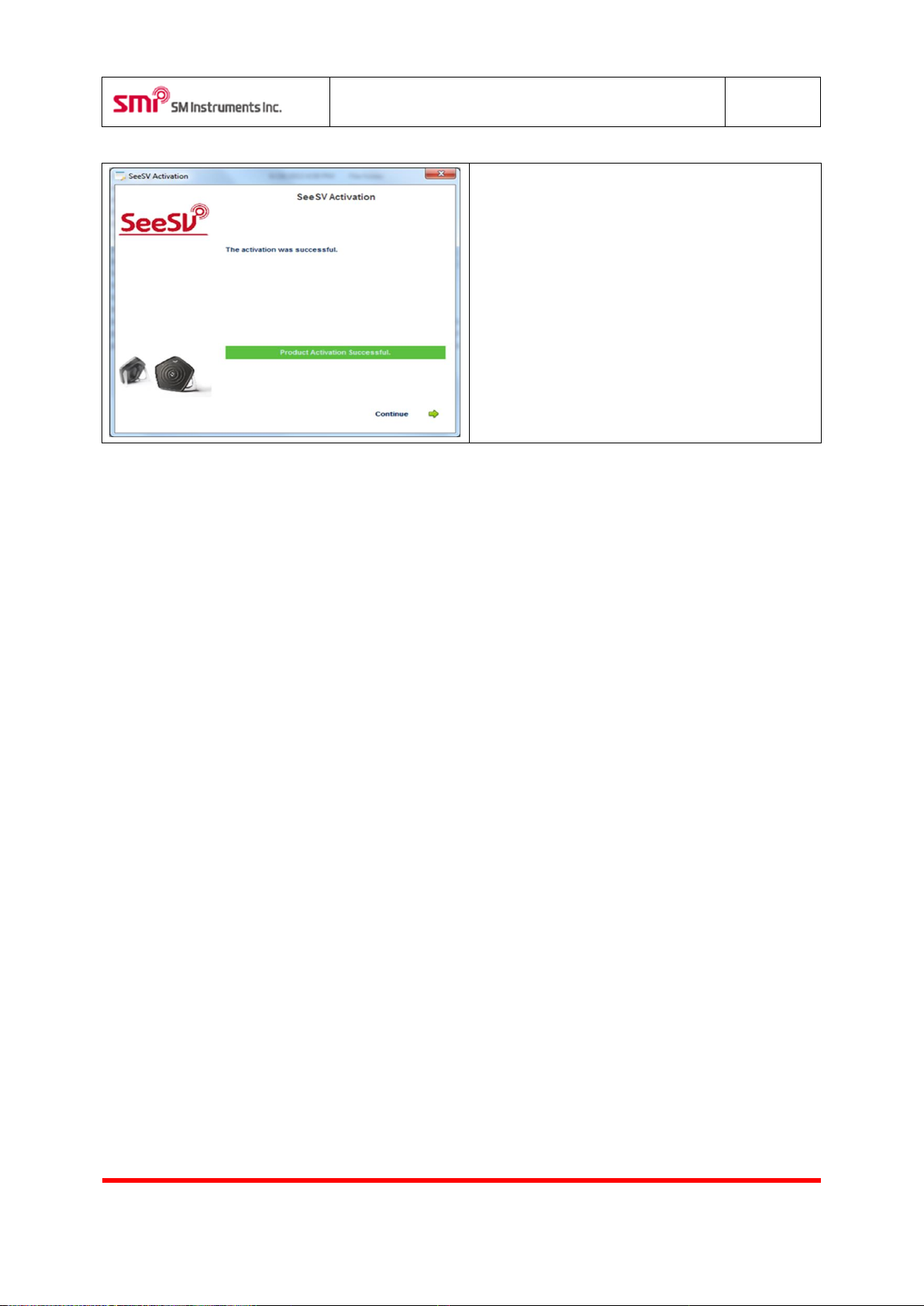
Software is successfully activated and click the
“Continue”.
The sound camera is ready for use.
Page 16
SeeSV-S205 User's Manual
Rev: 1.4.0
Doc. Type: User Manual
15
SM Instruments Co., Ltd.
Item
Description
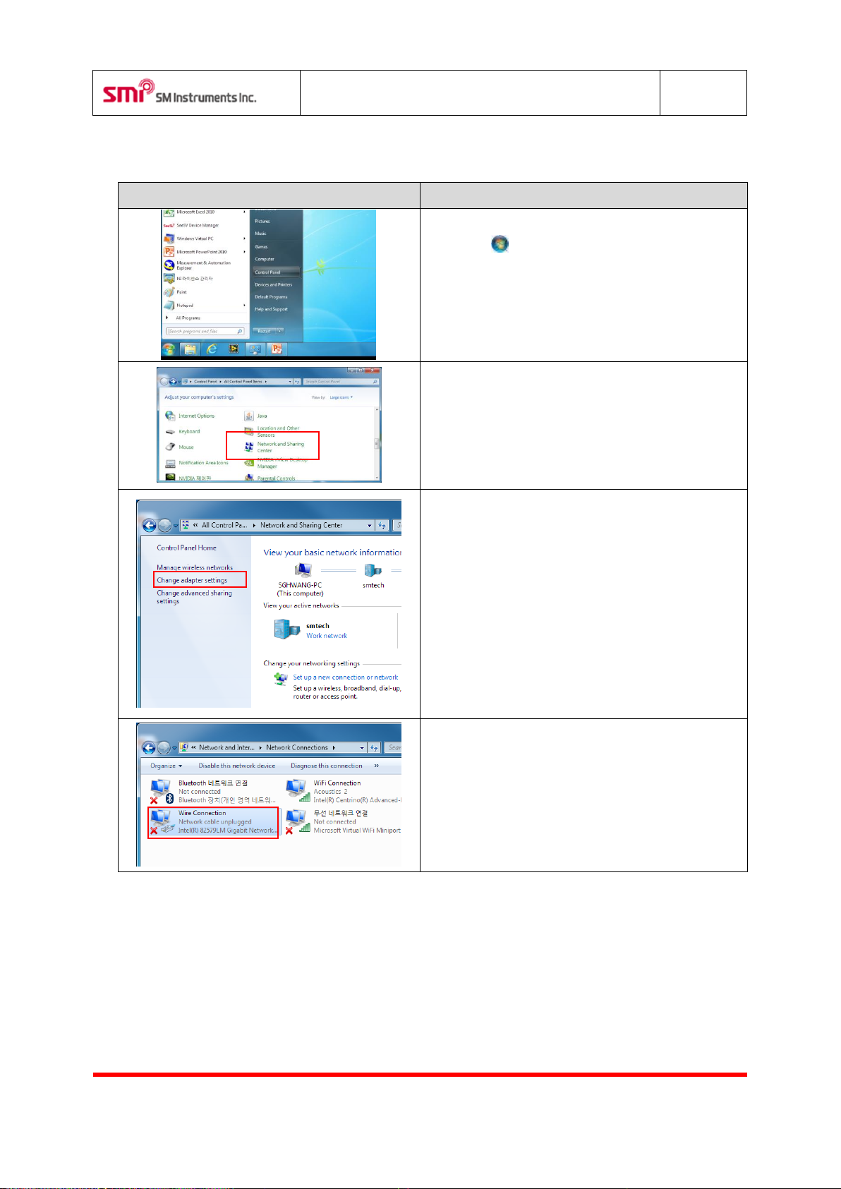
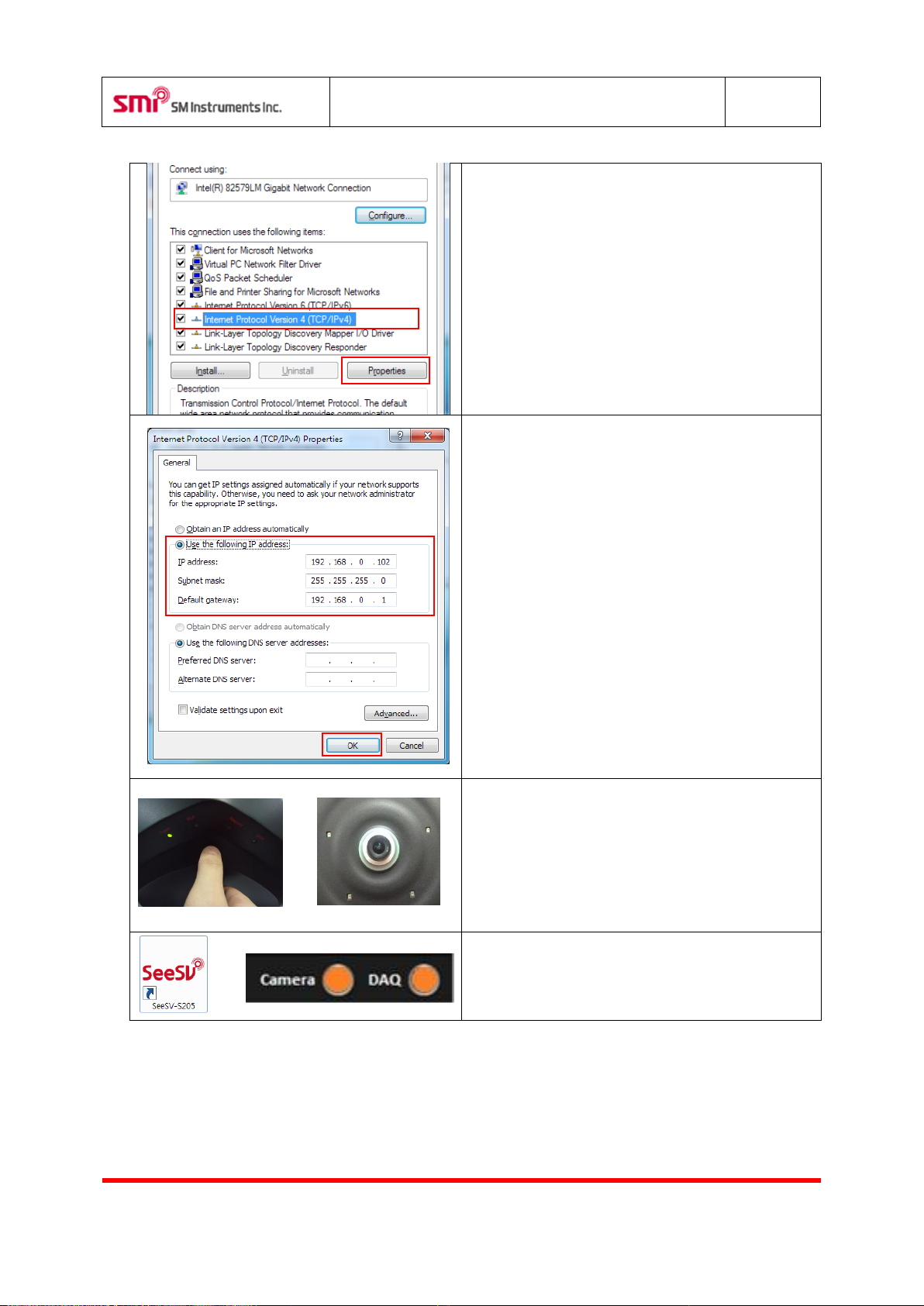
1. Open Network Connections by clicking the Start
button , and then clicking Control Panel.
2. Click the Network and sharing Center.
3. Click “Change adapter settings”.
4. Double Click “Wire connection”.
4.3 IP Config
Page 17
SeeSV-S205 User's Manual
Rev: 1.4.0
Doc. Type: User Manual
16
SM Instruments Co., Ltd.
5. Click the “Internet Protocol Version 4(TCP/IPv4)”,
and then click “Properties”.
6. Click the “Use the following DNS server
addresses”, and then, write in the boxes.
“IP address: 192. 168. 0. 102”
“Subnet mask: 255. 255. 255. 0”
“Default gateway: 192. 168. 0. 1”
Click “OK”.
Tip: Except IP address last number 6, 10, and 90
※ Can’t use more than 2 devices at the same time.
>>
7. Check connection to main body and pc. Turn on
power. Wait until lamp of the main body turns
green.
>>
8. Run SeeSV software. Check lamp to DAQ and
Camera.
Page 18
SeeSV-S205 User's Manual
Rev: 1.4.0
Doc. Type: User Manual
17
SM Instruments Co., Ltd.
Button status
Description
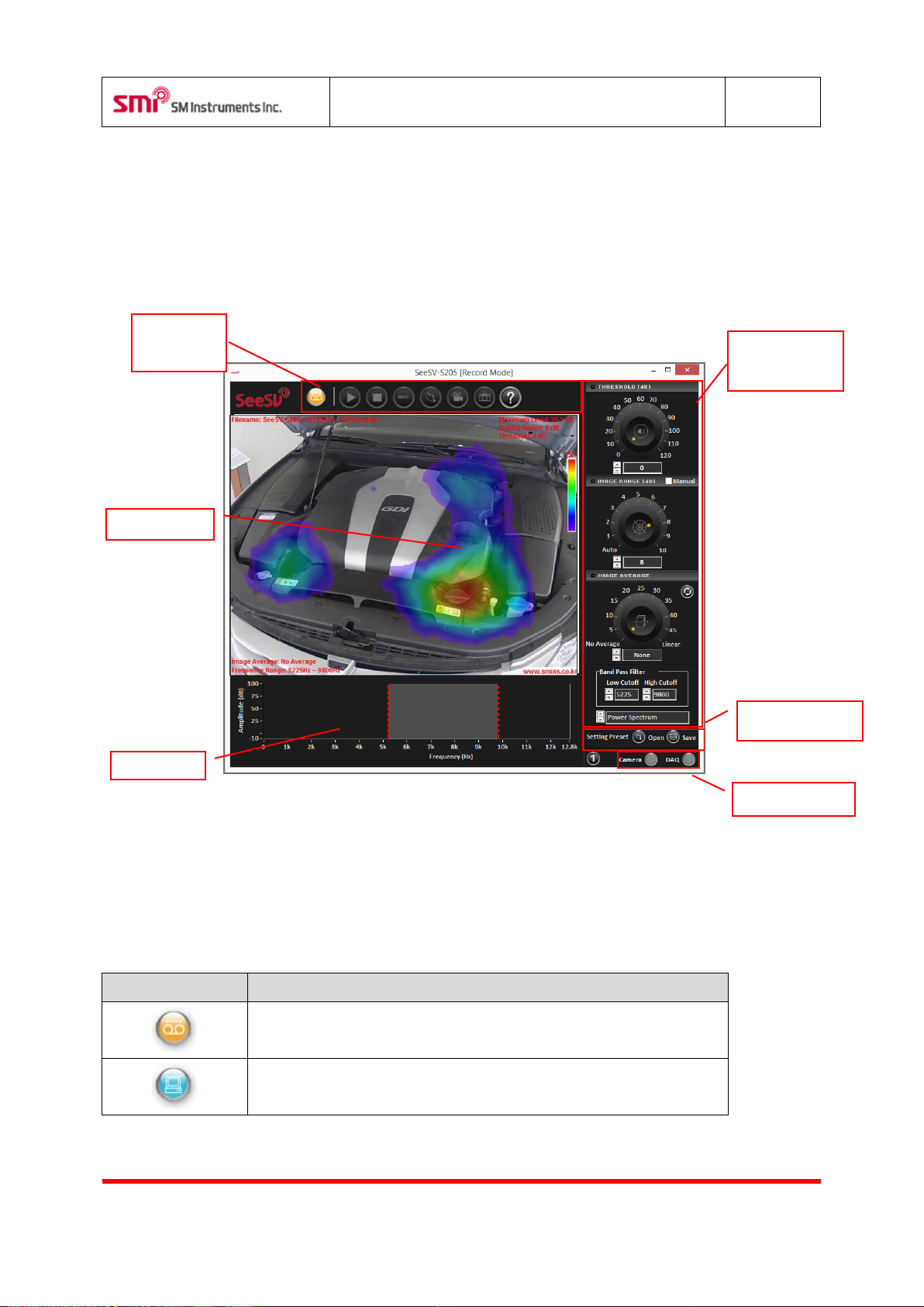
Record mode.
Replay mode.
Image Display
Device Status
Signal Graphs
Setting Preset
Measurement
Controller
Beamforming
Controller
5 Software Functions
Run the software and following screen will appear.
5.1 Software Mode
Select software mode using this button (Record or Replay). Selected mode can be confirmed by the color
and icon of the button..
Page 19
SeeSV-S205 User's Manual
Rev: 1.4.0
Doc. Type: User Manual
18
SM Instruments Co., Ltd.
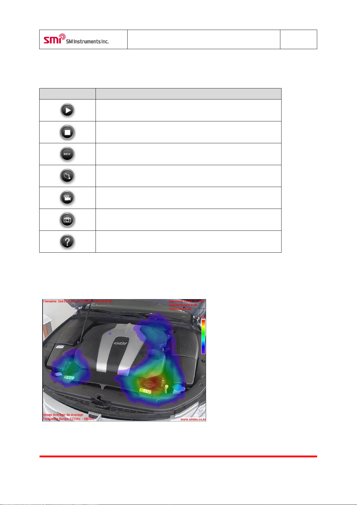
Button
Function
Play recorded data.
Stop (Record/Replay).
Record data.
Restore data file.
Convert data to movie file and save.
Save image as PNG (graphic) format.
Open the documents such as Application Guide, User’s Manual, and
Quick start Manual.
5.2 Control Buttons
Functions of each button are as follows.
5.3 Sound Camera Image
Display the camera, beam power overlaid image and measurement information.
Page 20
SeeSV-S205 User's Manual
Rev: 1.4.0
Doc. Type: User Manual
19
SM Instruments Co., Ltd.
Value
Meaning
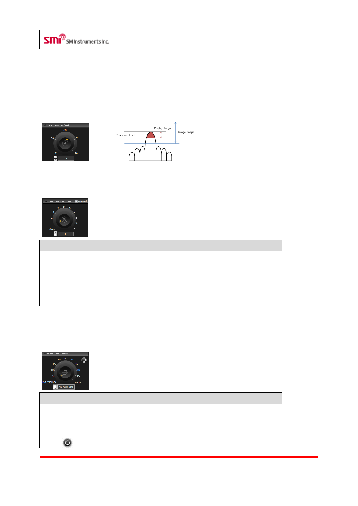
Manual Scale
Manually select Max/Min level. Max/Min level is located in Advanced
Setting.
0.01~10
Display beam power level between Max and (Max - adjusted value). If
select 3, displayed level will be [“Max”~ “Max-3”].
Auto Scale
Adjust displayed level of beam power automatically.
Adjust
Description
None
No averaging.
Exp.1~Exp.49
Exponential average of adjusted number of images.
Linear
Linear image average.
Refresh image average.
5.4 Image Threshold
Adjust the threshold level of the beam power which is displayed on the display window. Beam power below
the threshold level will not be shown. If the current beam power is less than the threshold level, it will not be
shown. When the threshold level is higher than minimum value of the image range, contour image will only
include the values between maximum values of the image range and the threshold level.
5.5 Image Range
Adjust displayed range of the beam power level. [“Max beam power” – “Image Range”] will be presented.
5.6 Image Average
Adjust averaging of the beam power image.
Page 21
SeeSV-S205 User's Manual
Rev: 1.4.0
Doc. Type: User Manual
20
SM Instruments Co., Ltd.
Mode
Description
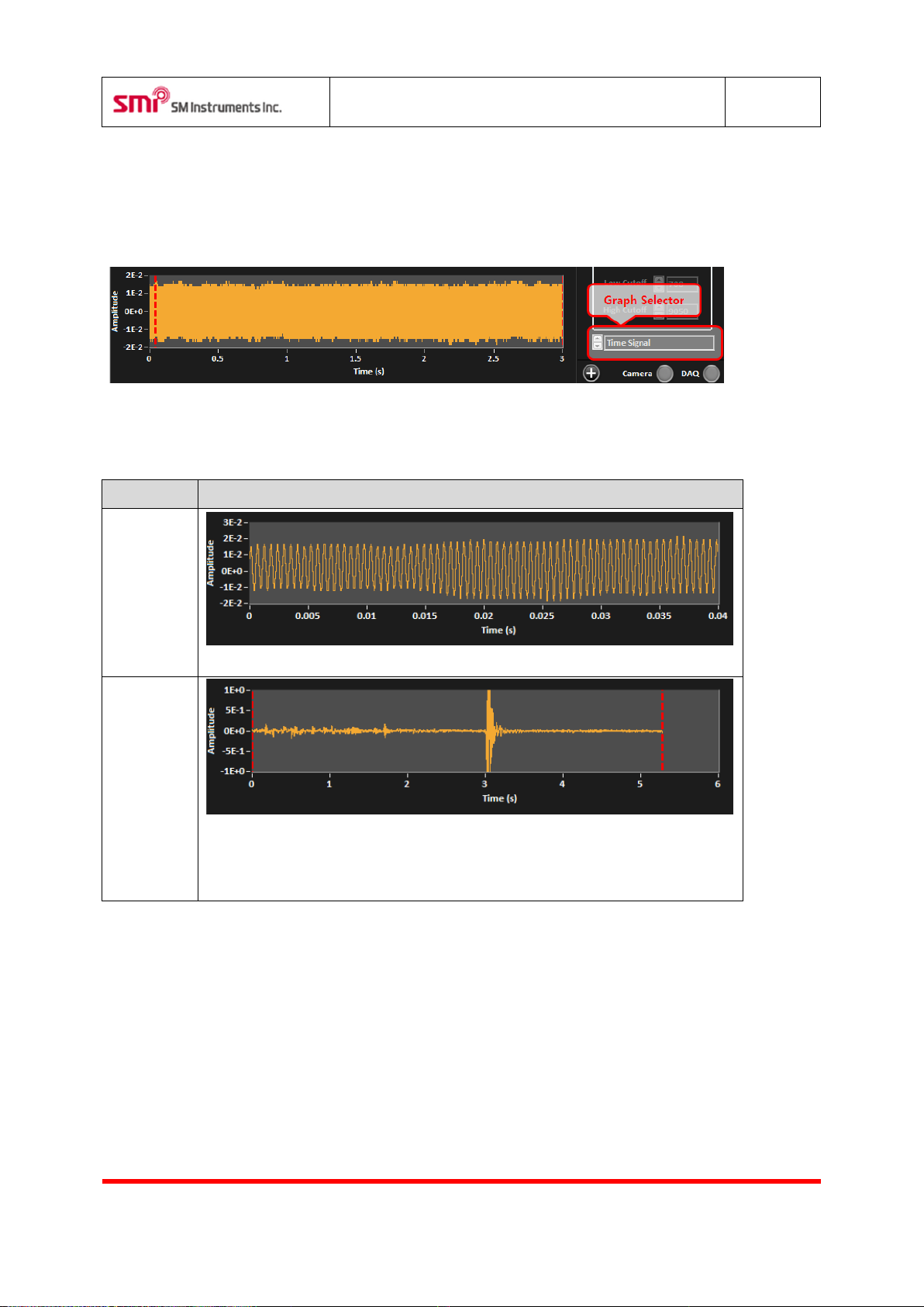
Record
Displays instantaneous signal of the microphone on real –time (0.04 sec).
Replay
Displays whole range of recorded data of the microphone. Use the mouse or
cursor key to adjust the section of replay section between two red-dotted cursors.
The image will be displayed according to the position of the first cursor.
5.7 Signal Graphs
Display time signal of the microphone, power spectrum, 1/3 octave and trend of beam power level. Use the
Graph Selector control outlined in red to select the type of graph.
5.7.1 Time Signal of Microphone
Displays time history signal of the microphone selected.
Page 22
SeeSV-S205 User's Manual
Rev: 1.4.0
Doc. Type: User Manual
21
SM Instruments Co., Ltd.
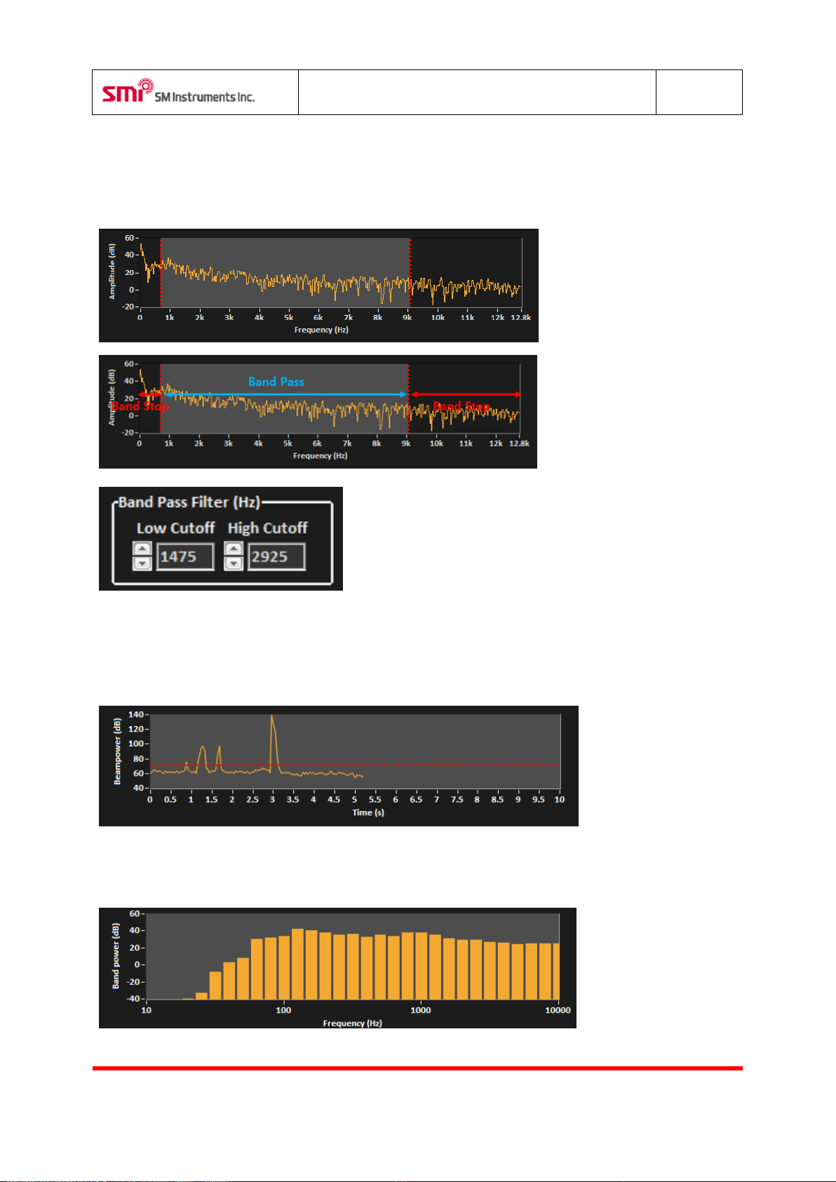
5.7.2 Power Spectrum of Microphone
Displays power spectrum of the microphone selected. Adjust band pass filter using the two cursors. Adjusted
range will be highlighted. Frequency range of the filter can be adjusted using the "Band Pass Filter" controls.
5.7.3 Level Trend of Beampower
Displays of the beam power level trend for 10 sec. The red-dotted line is the threshold, and orange-dotted
line is the trigger level when the record mode is "trigger".
5.7.4 1/3 Octave Level of Microphone
Displays of the 1/3 octave band level of the microphone signal.
Page 23
SeeSV-S205 User's Manual
Rev: 1.4.0
Doc. Type: User Manual
22
SM Instruments Co., Ltd.
Color
Description
Not connected.
Connected.
Status
Description
Threshold, Image Range & average, Band Pass Filter, Graphs, & Basic
Display Icons
Path, Record, Sound Camera, Display Configuration, and Firmware
Update setting
Image Calibration, Replay & Record Advanced setting, and DAQ status
setting
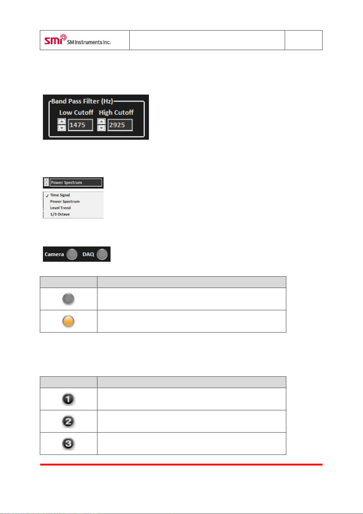
5.8 Band Pass Filter
Adjusts the band pass filter of the beampower.
5.9 Graph Selector
Selects graph to display.
5.10 Device Status Lamp
Displays the status of the connection of the sound camera.
5.11 Setup
Displays or hides items for settings.
Page 24
SeeSV-S205 User's Manual
Rev: 1.4.0
Doc. Type: User Manual
23
SM Instruments Co., Ltd.
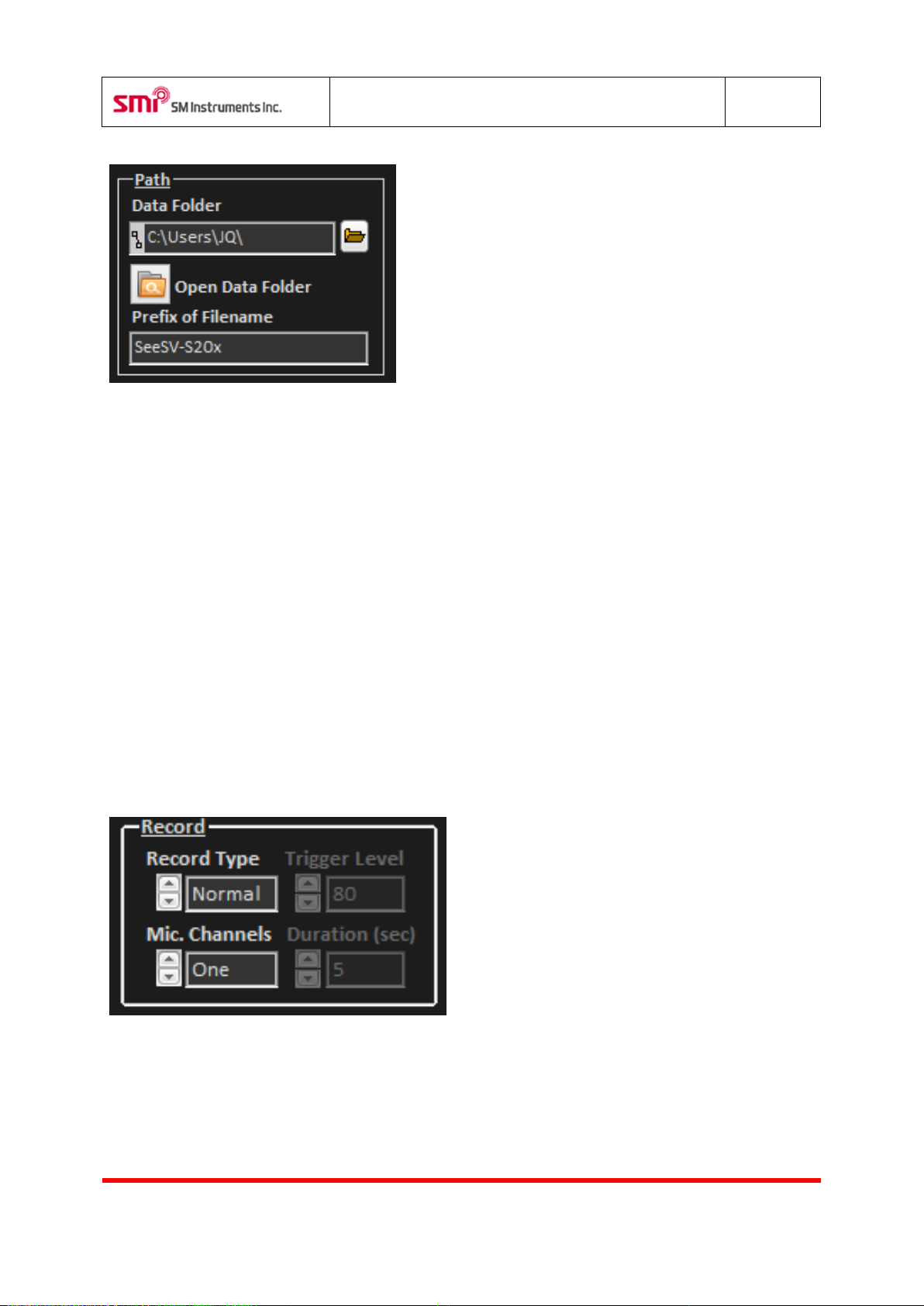
5.11.1 Data Folder
Defines path of the data file. This path will be the default setting for the following:
- Save data
- Open data file
- Save screenshot
- Convert/save movie
5.11.2 Open Data Folder
Opens the data folder.
5.11.3 Prefix of Filename
Sets prefix of filename to be saved. If the prefix is “SeeSV-S20x”, the filename will be as following.
“SeeSV-S20x_[yyyymmdd][HHMMSS].tdms”
5.11.4 Record Type
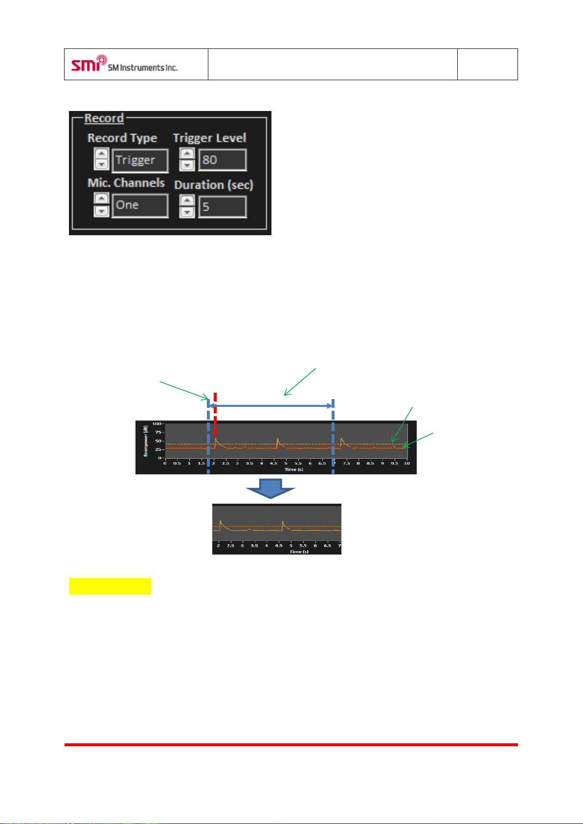
Sets record type.
- Normal: Continuously saves data when the "Record" and "Stop" buttons are pressed.
- Trigger: After the "Record" button is pressed, records data when it exceeds the trigger level of the
beam power
Page 25
SeeSV-S205 User's Manual
Rev: 1.4.0
Doc. Type: User Manual
24
SM Instruments Co., Ltd.
occurred.
Level
hold
5.11.5 Trigger Level
Sets trigger level.
5.11.6 Duration
Sets the recording time in seconds when the trigger is activated.
Duration
Pre-trigger
buffer
Trigger is
(Second,
Trigger
5.11.7 Mic. Channels
Sets number of Microphone channels
- One
- All
Thres
Page 26
SeeSV-S205 User's Manual
Rev: 1.4.0
Doc. Type: User Manual
25
SM Instruments Co., Ltd.
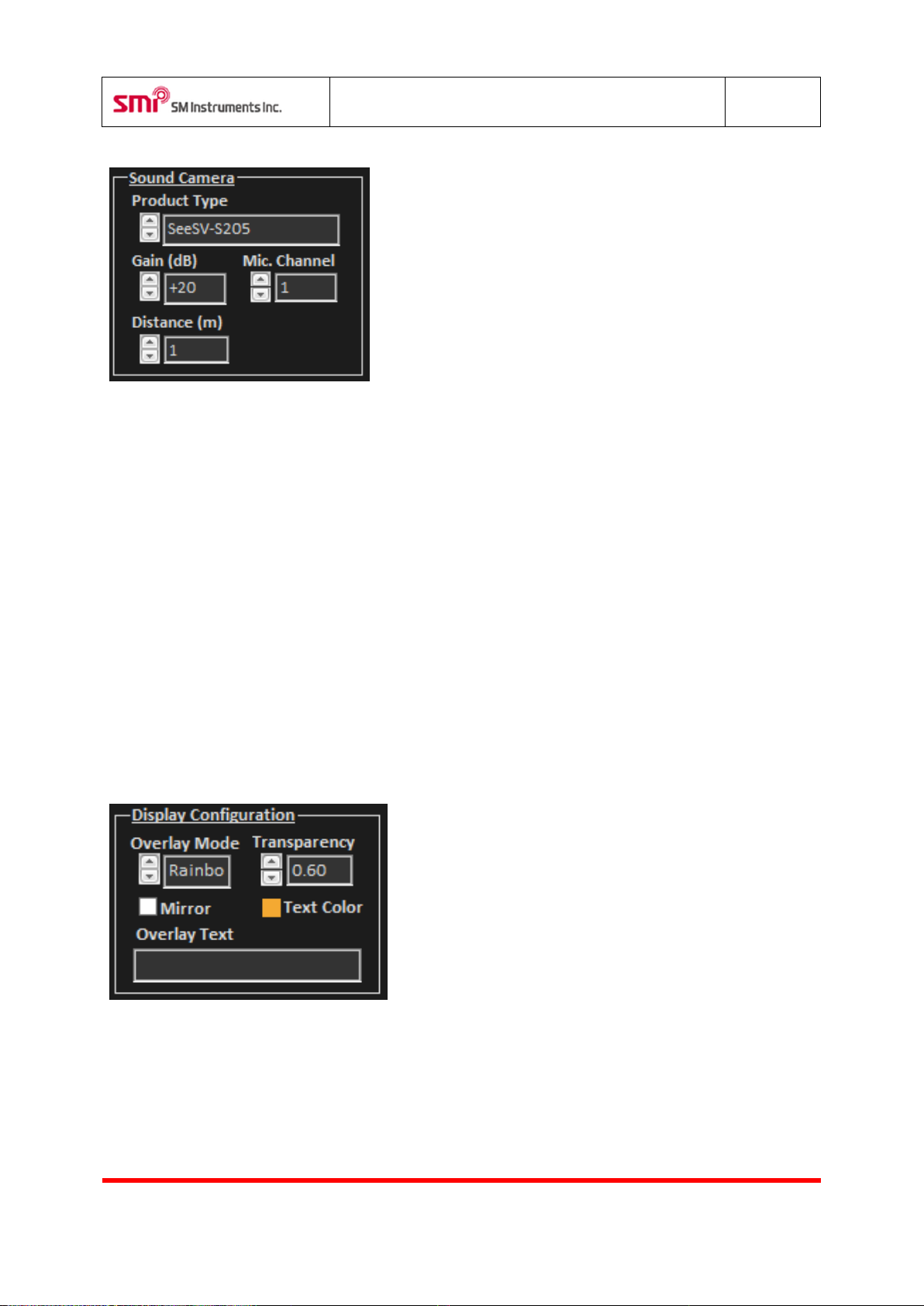
5.11.7 Product Type
Select model of sound camera being used.
- SeeSV-S205
- SeeSV-S200
-
5.11.8 Mic Gain
Set the gain of the microphone. The range of gain is -10dB/0dB/+10dB/+20dB/+30dB.
5.11.9 Mic Channel
Select the microphone to be measured and displayed.
5.11.10 Distance (m)
Sets distance between a sound camera and noise source.
5.11.11 Max/Min Level
When the Display Range is set to User Scale, adjust Max Level and Min Level to be displayed.
Page 27
SeeSV-S205 User's Manual
Rev: 1.4.0
Doc. Type: User Manual
26
SM Instruments Co., Ltd.
Mode
Description
Gray
Rainbow
Binary
Temperature
Gradient
Value
Description
0.1
0.9
Status
Description
ON
OFF
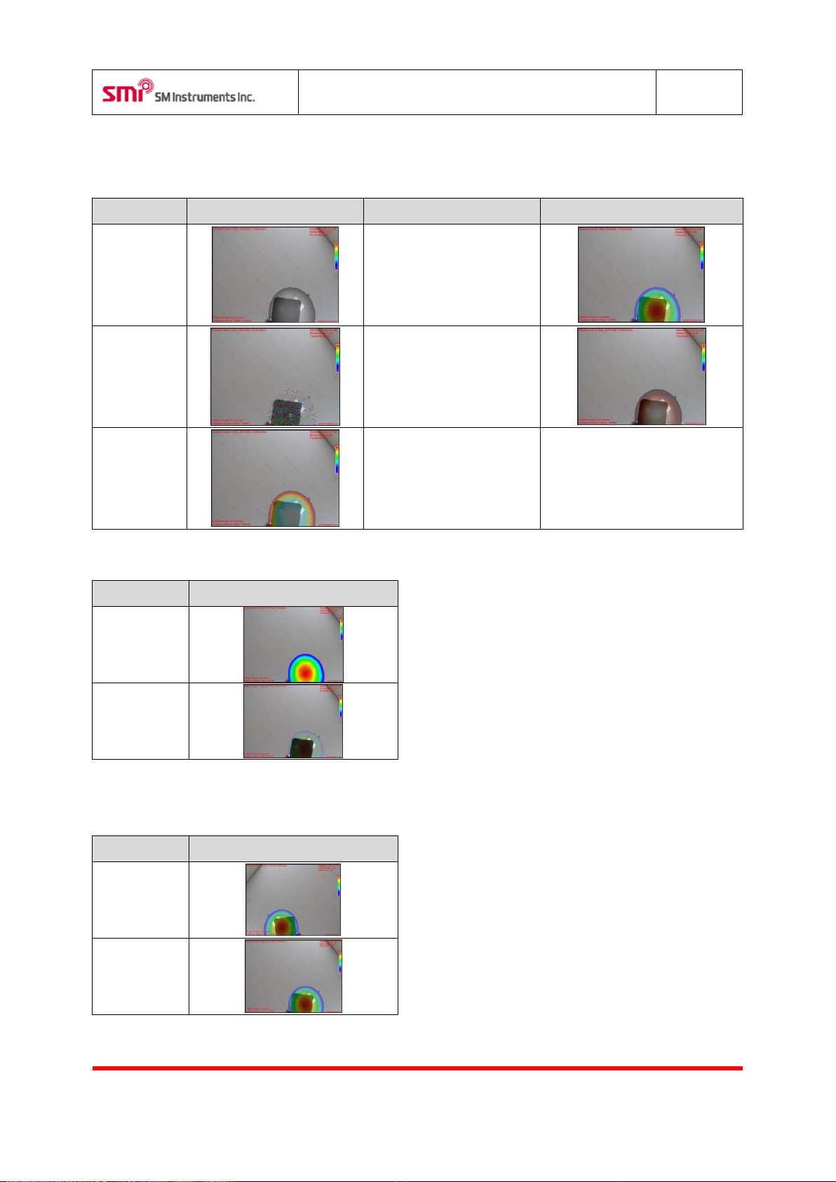
5.11.12 Overlay Mode
Select color set of beam power.
5.11.13 Transparency
Set transparency of displayed beam power. 0 (opaque) 1 (transparent)
5.11.14 Mirror Mode
Show mirror image.
Page 28
SeeSV-S205 User's Manual
Rev: 1.4.0
Doc. Type: User Manual
27
SM Instruments Co., Ltd.
Status
Description
Before
After
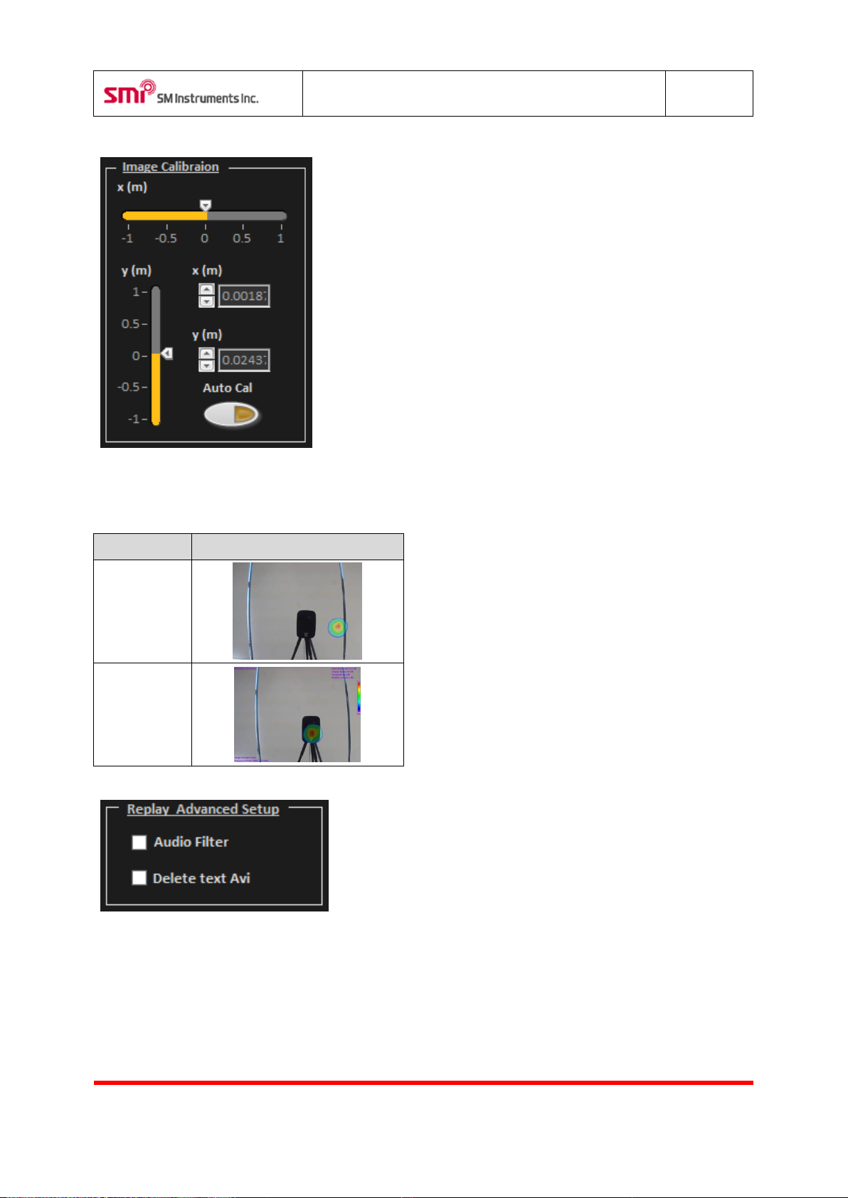
5.11.14 Image Calibration
Show automatic image calibration.
5.11. 15 Replay Advanced Setup
Selects replay advanced setup.
- Audio Filter: Amplifying the volume from noise source when a user coverts t은 file to avi file.
- Delete text Avi.: Removing text data on an avi file.
Page 29
SeeSV-S205 User's Manual
Rev: 1.4.0
Doc. Type: User Manual
28
SM Instruments Co., Ltd.
Shortcut
Function
Ctrl+1
Display time history signal of the microphone.
Ctrl+2
Display power spectrum of the microphone.
Ctrl+3
Display trend graph of beam power level.
Ctrl+4
Display 1/3 octave band graph of the microphone.
Left Cursor
Move first cursor to left at time signal graph of review mode
Right Cursor
Move first cursor to right at time signal graph of review mode
Up Cursor
Increase image threshold.
Down Cursor
Decrease image threshold.
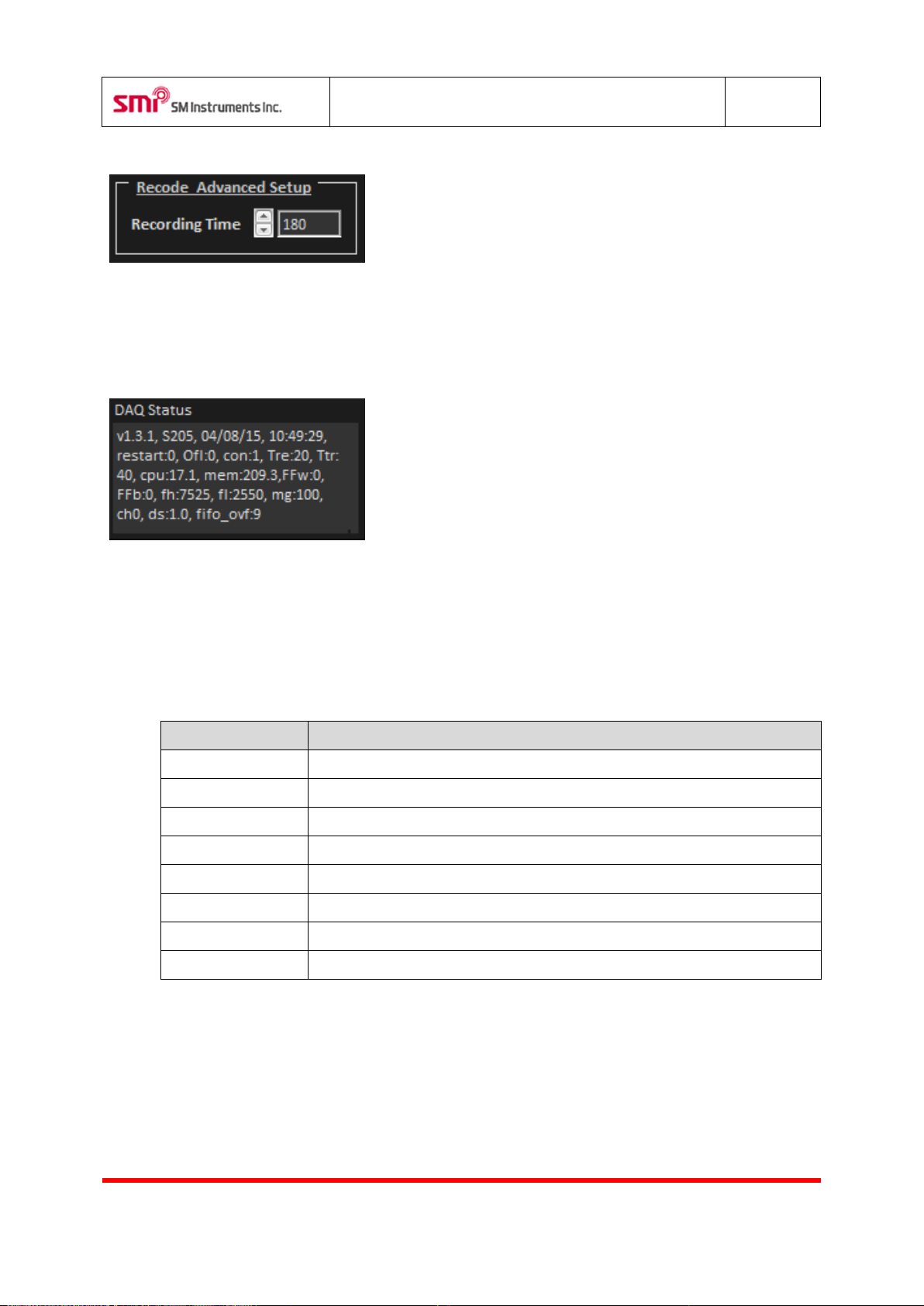
5.11.15 Recording Advanced Setup
Sets Recording Time up to 180 seconds.
5.11.16 DAQ Status
Shows a sound camera device information.
6 Software shortcut keys
Page 30
SeeSV-S205 User's Manual
Rev: 1.4.0
Doc. Type: User Manual
29
SM Instruments Co., Ltd.
Item
Description
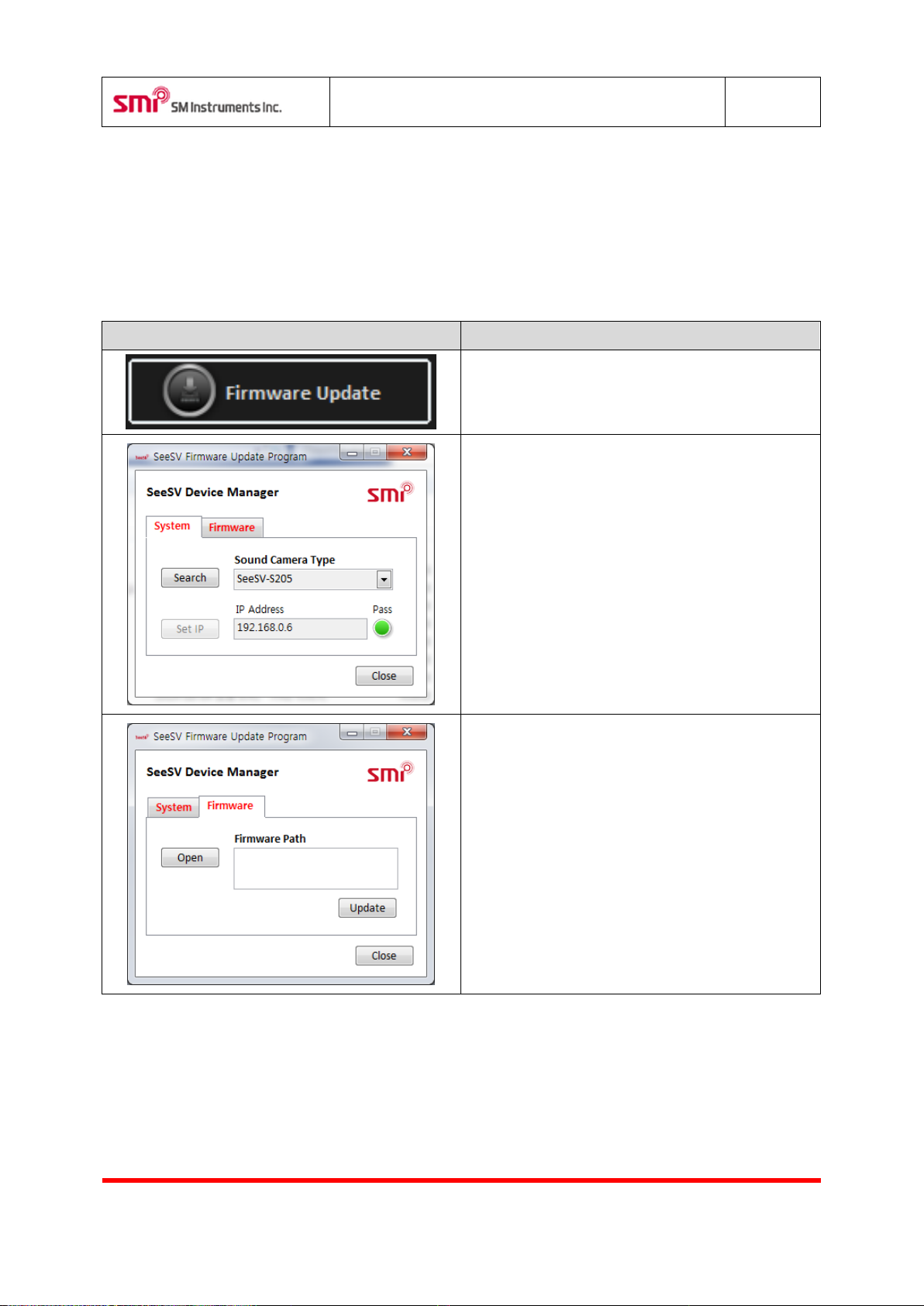
Run SeeSV software and then click the button.
Click the button “Firmware”.
Click the button “Open”.
7 Maintenance and Troubleshooting
7.1 Sound Camera Firmware Update
7.1.1 How to update Sound Camera Firmware
Page 31
SeeSV-S205 User's Manual
Rev: 1.4.0
Doc. Type: User Manual
30
SM Instruments Co., Ltd.
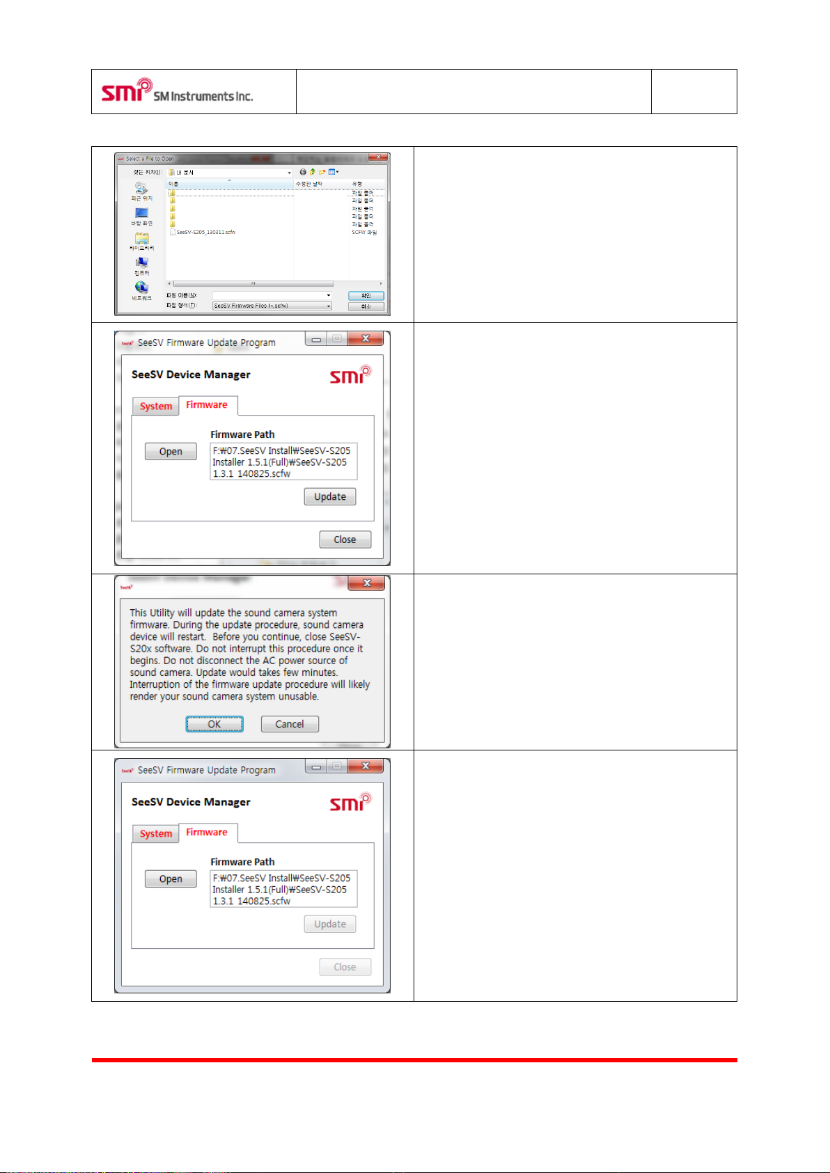
Select the firmware file which is distributed with the
installation file.
(*.scfw file)
Click “Update” to start.
Before proceeding and during the update.
- Confirm the connection of sound camera.
- Keep power on.
- Keep connection of sound camera connected.
Update can take several minutes. Wait for notification
popup before proceeding.
Page 32
SeeSV-S205 User's Manual
Rev: 1.4.0
Doc. Type: User Manual
31
SM Instruments Co., Ltd.
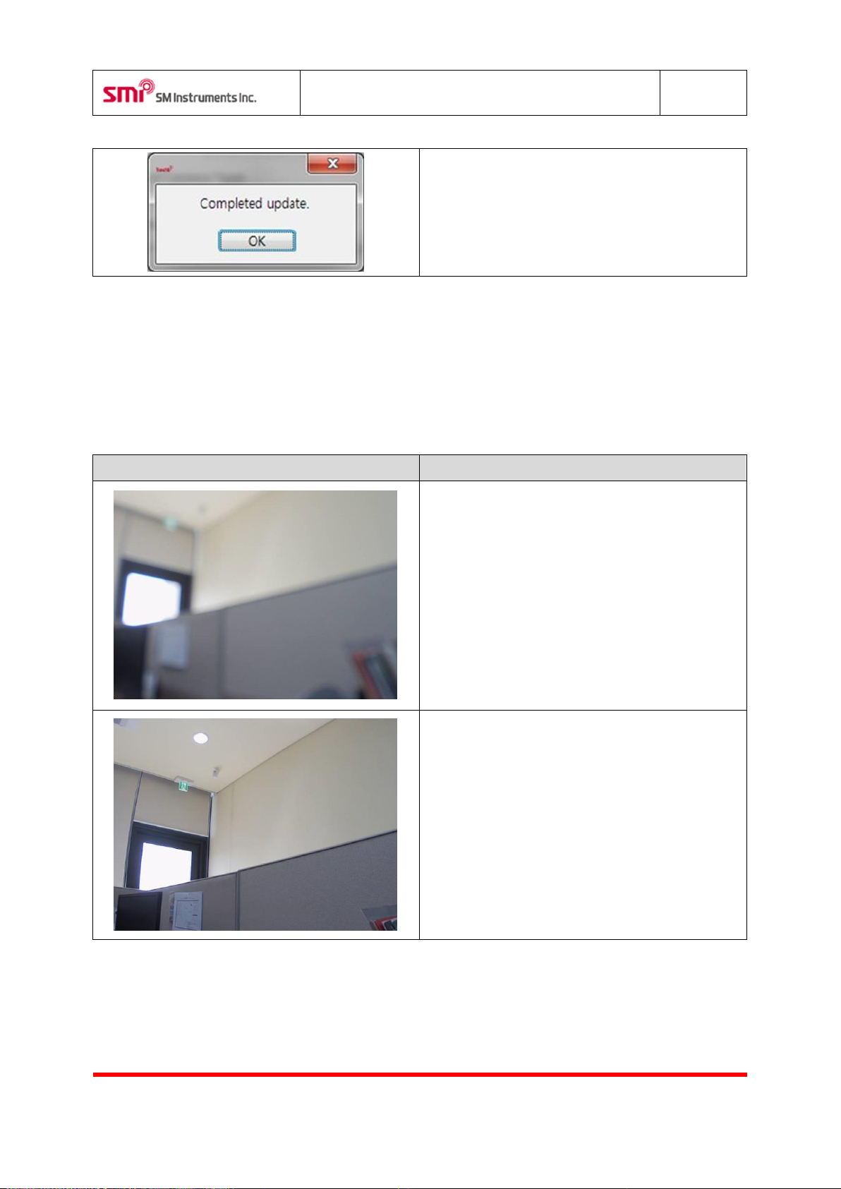
Update completed. Run sound camera software to
ensure update was successful.
Item
Description
Previous image to be improved: Abnormal focus
image.
After image improvement: Normal focus image.
7.2 Modify the focus of sound camera
7.2.1 How to modify the focus of sound camera
Page 33
SeeSV-S205 User's Manual
Rev: 1.4.0
Doc. Type: User Manual
32
SM Instruments Co., Ltd.
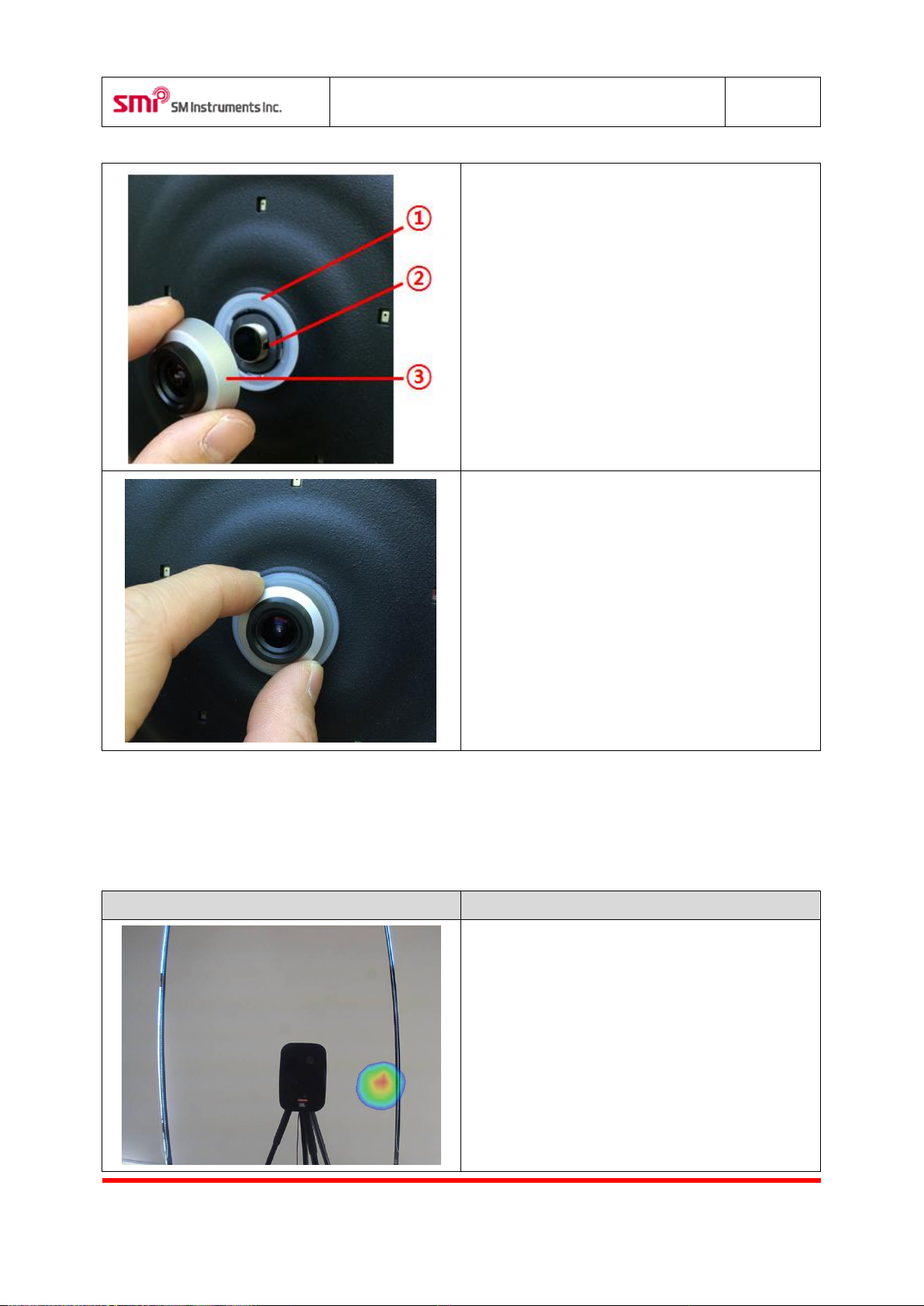
Camera lens hardware part.
1. CAM Status LED Indicator
2. Lens Fixed Screw
3. Lens
Camera focus control method: Turn to the left and
right lens fixed focus.
※ Cause: If you turn to the right to force the lens
may be damaged.
Item
Description
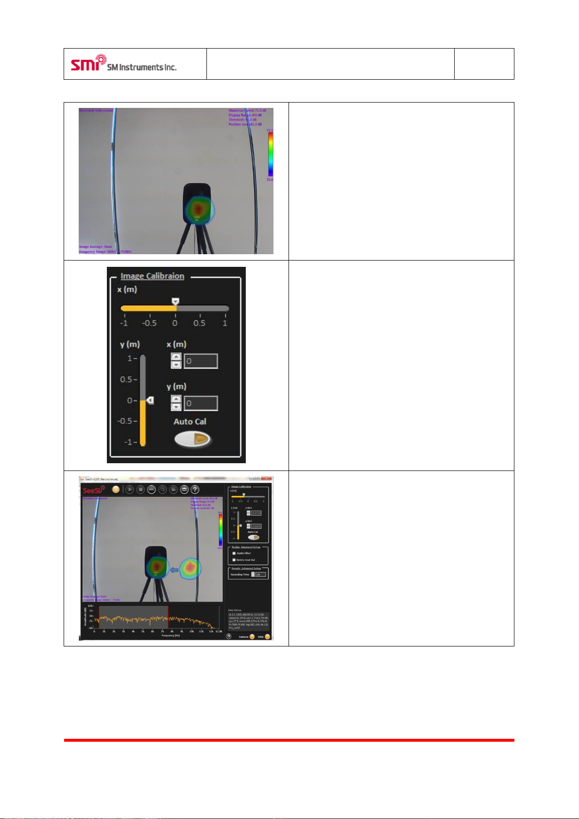
Previous image to be improved: Abnormal focus
image.
(Before using Image calibration)
.
7.3 Modify the position of overlay image
7.3.1 How to modify the position of overlay image
Page 34
SeeSV-S205 User's Manual
Rev: 1.4.0
Doc. Type: User Manual
33
SM Instruments Co., Ltd.
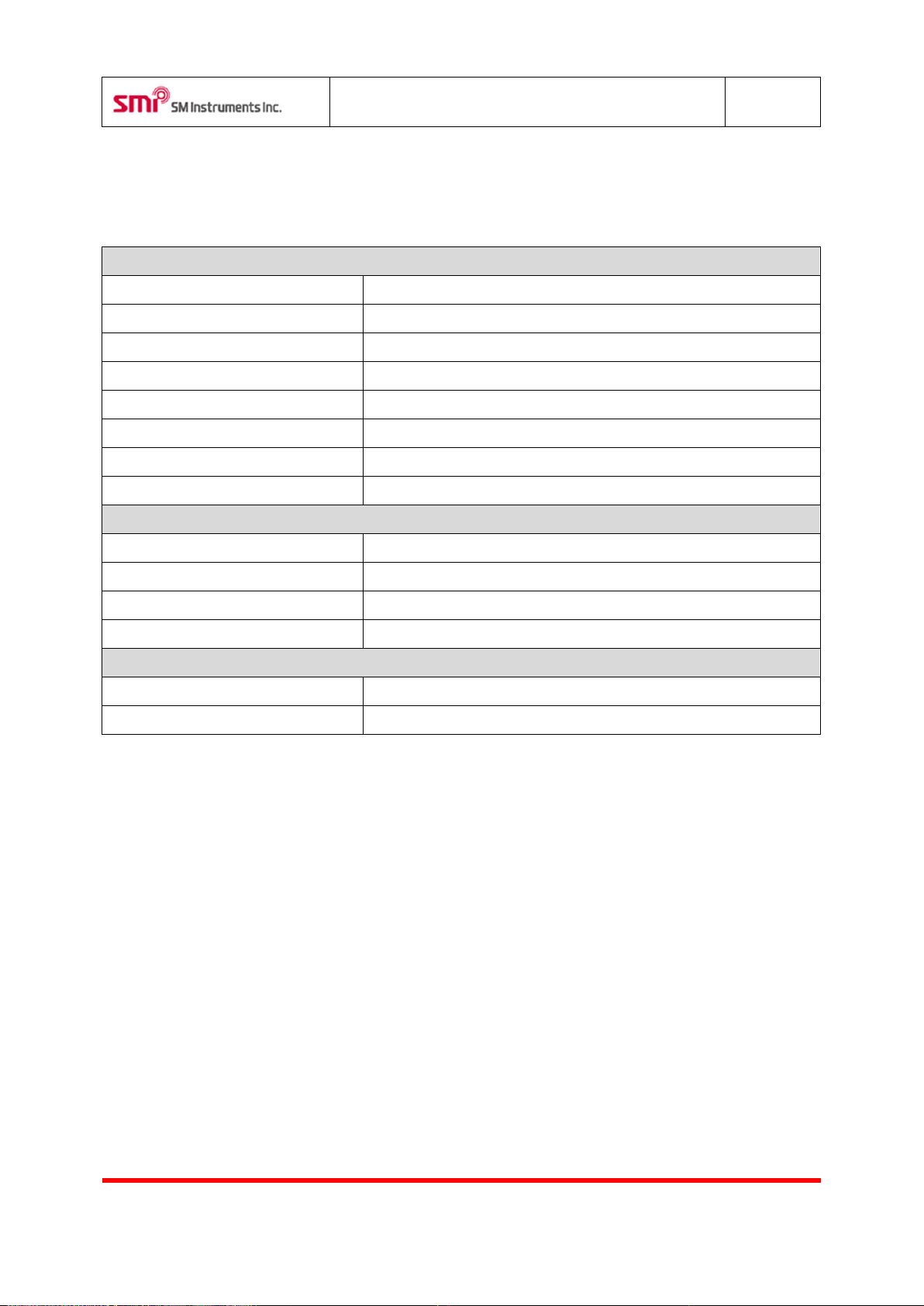
After image improvement: Normal focus image.
(After using Image Calibration)
Developer's menu is displayed by click the "ctrl + ]"
key. And Click “x(m) or y(m)” button manually. Or you
can control image calibration by “Auto Cal”.
Overlay image control method:
1. Click the Display control icon “Auto Cal”.
2. Click center to overlay image. Drag and
drop position to noise source.
Page 35
SeeSV-S205 User's Manual
Rev: 1.4.0
Doc. Type: User Manual
34
SM Instruments Co., Ltd.
Microphone Array
Microphone Type
Digital MEMS Microphone
Number of Microphones
30
Microphone Sensitivity
70 mV/Pa
Array Diameter
350 mm
Frequency Range (Full)
350 to 12000 Hz
Frequency Range (Recommended)
2000 to 10000 Hz
Measurement Distance
0.2 to 5.0 m (Recommended)
Weight
2.4kg
Data Acquisition and Processing
Sampling Rate
25.6k S/s/ch
Image Update Rate
25 FPS
Imaging Algorithm
Beamforming (delay and sum)
Image Ranging
Automatic/Manual
Environmental Condition
Operation Temperature
-20 to 50°C
Humidity
10 to 85 % RH
8 Specifications
Page 36
SeeSV-S205 User's Manual
Rev: 1.4.0
Doc. Type: User Manual
35
SM Instruments Co., Ltd.
9 <CAUTION>
This device complies with part 15 of the FCC Rules. Operation is subject to the following two conditions:
(1) This device may not cause harmful interference, and
(2) This device must accept any interference received, including interference that may cause undesired
operation.
Caution: Any changes or modifications to the equipment not expressly approved by the party
responsible for compliance could void user’s authority to operate the equipment.
This appliance and its antenna must not be co-located or operation in conjunction with any other
antenna or transmitter.
A minimum separation distance of 20 ㎝ must be maintained between the antenna and the person
for this appliance to satisfy the RF exposure requirements.
CAUTION RISK OF EXPLOSION IF BATTERY IS REPLACED BY AN INCORRECT TYPE.
DISPOSE OF USED BATTERIES ACCORDING TO THE INSTRUCTIONS.
• The product can be damaged by external shock.
• Please do not disassemble the product.
• Please check rated voltage when you charge the product. (for wireless camera model only)
• Please keep away from fire and liquid.
Insuring Indoor Use in 5.15-5.25 GHz Band (15.407 (ii))
FCC 15.407(ii) states: "For an indoor access point operating in the band 5.15-5.25 GHz, the maximum
conducted output power over the frequency band of operation shall not exceed 1 W provided the
maximum antenna gain does not exceed 6 dBi. In addition, the maximum power spectral density shall
not exceed 17 dBm in any 1 megahertz band. If transmitting antennas of directional gain greater than
6 dBi are used, both the maximum conducted output power and the maximum power spectral density
shall be reduced by the amount in dB that the directional gain of the antenna exceeds 6 dBi"
 Loading...