

Page 1

Portable Ultrasonic Camera
BATCAM 2.0
User Manual
Find Quality Products Online at: [email protected]
www.GlobalTestSupply.com
Page 2

BATCAM 2.0
1
Contents
General Outline ....................................................................................................................................................................................................... 2
Product Configuration ......................................................................................................................................................................................... 2
Hardware Feature and Configuration ........................................................................................................................................................... 3
Connect External Device and How to Use the Device......................................................................................................................... 3
I. Connection Port Description ..................................................................................................................................................... 4
II. How to Connect Power Adaptor ............................................................................................................................................. 4
III. Product Action Status Indicator(LED) .................................................................................................................................... 5
IV. Interface Port Connection .......................................................................................................................................................... 6
V. How to Use Power Button ......................................................................................................................................................... 7
VI. How to Use Record Button ........................................................................................................................................................ 8
Component Description ................................................................................................................................................................................... 10
I. Power Device ................................................................................................................................................................................. 10
II. User Manual ................................................................................................................................................................................... 10
III. Portable Hard Case ..................................................................................................................................................................... 10
IV. Hand Strap ...................................................................................................................................................................................... 11
Software ................................................................................................................................................................................................................... 12
I. Main Screen(User Interface) ................................................................................................................................................... 12
II. Icon(object) and Function Description .............................................................................................................................. 13
III. Beam Forming Setting .............................................................................................................................................................. 26
IV. Additional Setting ........................................................................................................................................................................ 28
V. Product Management and A/S ............................................................................................................................................. 29
Product Specification ......................................................................................................................................................................................... 30
Components and other specifications ...................................................................................................................................................... 30
Product Certification .......................................................................................................................................................................................... 31
I. Electromagnetic Compatibility .............................................................................................................................................. 31
II. FCC Compliance ........................................................................................................................................................................... 31
III. CE Compliance .............................................................................................................................................................................. 31
IV. KC Compliance .............................................................................................................................................................................. 31
V. Battery ............................................................................................................................................................................................... 31
Precautions ............................................................................................................................................................................................................. 33
Find Quality Products Online at: [email protected]
www.GlobalTestSupply.com
Page 3
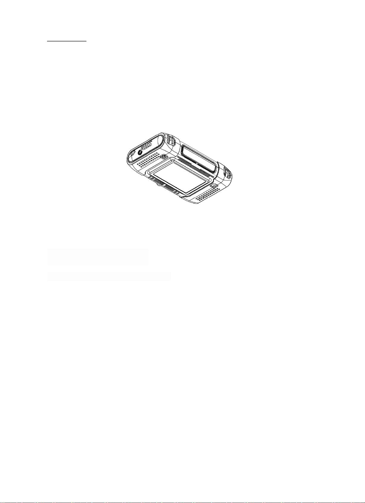
BATCAM 2.0
2
General Outline
BATCAM 2.0 is a portable ultrasonic camera that provides visual insight into an array of microphones and
abnormal locations such as gas, air leaks and electrical discharges with high-speed FPGA-based processors.
This document describes the components of BATCAM 2.0 and provides information on how the device works.
Product Configuration
The BATCAM 2.0 product consists of the following:
Find Quality Products Online at: [email protected]
www.GlobalTestSupply.com
Page 4

BATCAM 2.0
3
Hardware Feature and Configuration
The hardware features and configurations of BATCAM 2.0 are shown below.
Connect External Device and How to Use the Device
BATCAM 2.0 device body is equipped with an external device, such as a monitor, and a connector to connect
the power cable as shown below.
Find Quality Products Online at: [email protected]
www.GlobalTestSupply.com
Page 5
BATCAM 2.0
4
I. Connection Port Description
1) LEMO Connector: Connect the connector on the power adapter to the BATCAM 2.0 LEMO
connector to supply power and charge the internal battery.
2) Audio Jack: User can listen to the sound by connecting earphones to the audio jack of BATCAM
2.0.
3) HDMI Port: BATCAM 2.0 and the monitor can be connected to the HDMI connector to output the
videos being filmed or stored to the monitor.
4) USB Port: User can copy data stored in BATCAM 2.0 to a USB memory device or update internal
software.
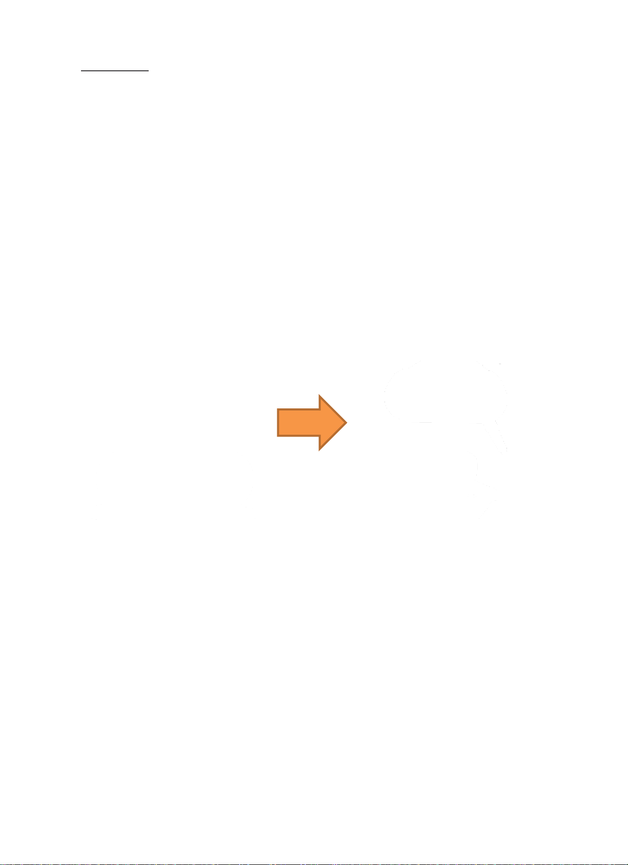
II. How to Connect Power Adaptor
Connect the LEMO connector of the BATCAM 2.0 power adapter in the direction shown.
When using the LEMO connector, connect and use the
connector by aligning the power connector groove inside the
left rubber packing with the red dot on the LEMO connector.
Find Quality Products Online at: [email protected]
www.GlobalTestSupply.com
Page 6

BATCAM 2.0
5
III. Product Action Status Indicator(LED)
1) Charging Status Indicator(Top Right)
When the power adapter connector is connected, charging is initiated and 'LED' is displayed on the right
side of the top of the product as shown below.
Not Charged
Charging
Charging Complete
2) Power Status Indicator(Top Left)
The Power Condition Indicator(LED) at the top left of the product can be used to check the power condition
of the product.
Power ON
Power OFF
Green Light On(Power ON) Green Light Off(Power OFF)
Red(Charging) Green(Charging Complete)
Find Quality Products Online at: [email protected]
www.GlobalTestSupply.com
Page 7

BATCAM 2.0
6
IV. Interface Port Connection
1) HDMI Output
User can connect BATCAM 2.0 and monitor with HDMI cable so that BATCAM 2.0 screen is output to monitor
as shown above.
2) USB Port
Image and video files stored in BATCAM 2.0 can be transferred to a memory device(FAT 32 format) via the
USB port. Here's how to copy data: The amount of time that is transferred may vary depending on the
number and capacity of the files stored. (There is no USB memory device available on the product.)
① Connect the USB memory device to the USB port located on the left.
② Connect the USB memory device and press the USB icon(object) on the right side of the BATCAM
2.0 main screen.
Find Quality Products Online at: [email protected]
www.GlobalTestSupply.com
Page 8
BATCAM 2.0
7
V. How to Use Power Button
With BATCAM 2.0 off, pressing the power button on the left side for 2 seconds will power on and the power
status indicator on the left side of the product will illuminate green. To turn off the power, press the power
button again for 2 seconds to turn off the power and the power status indicator lamp off.
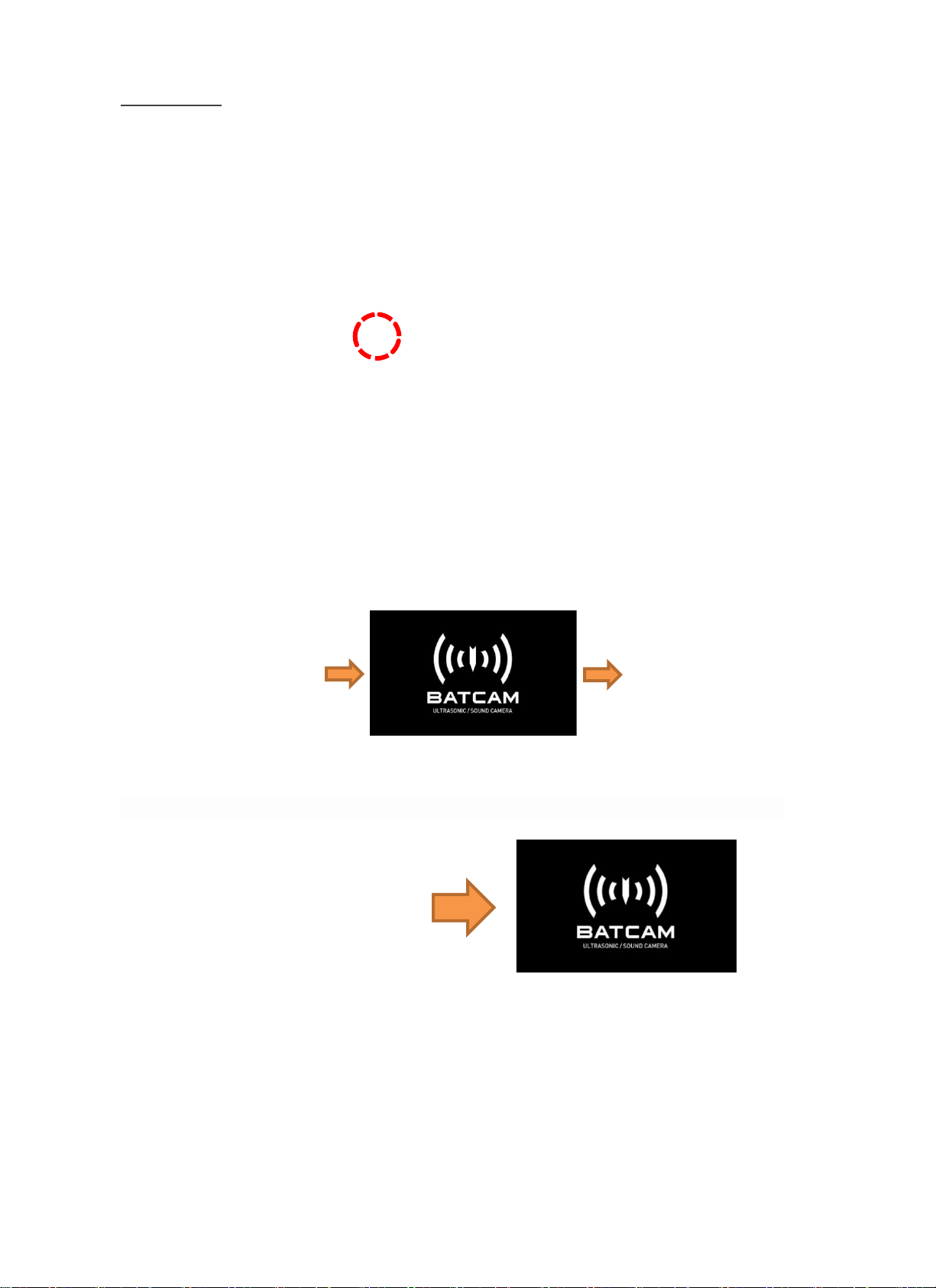
1) Power ON
When powered on, the company logo('SMI') and product logo('BATCAM') appear in order on the LCD screen,
and the software operates.
2) Power OFF
When you turn off the power, the product logo below appears on the LCD screen and ends its operation.
Find Quality Products Online at: [email protected]
www.GlobalTestSupply.com
Page 9
BATCAM 2.0
8
VI. How to Use Record Button
The record button allows you to save the screen you are measuring as an image(JPG) or a video(AVI). Here's
how to use it:
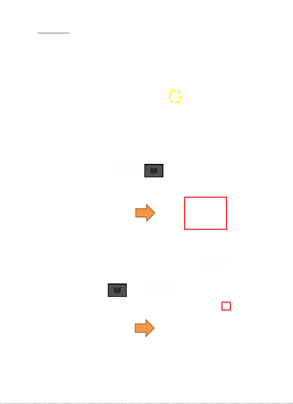
1) Save Image
A short press of the Record button saves the screen you are measuring as an image (JPG). The saved images
can be viewed by clicking the directory icon(object) on the right side of the main screen.
2) Save Video
Press and hold the Record button(2 seconds) to start filming the video(AVI) and an icon(object) appears at
the top of the screen to indicate that you are recording, as shown in the figure below on the right. Press
and hold the record button(for 2 seconds) to end the shoot and save the video automatically. User can
view saved videos by clicking the directory icon(object) on the right side of the screen.
Find Quality Products Online at: [email protected]
www.GlobalTestSupply.com
Page 10
BATCAM 2.0
9
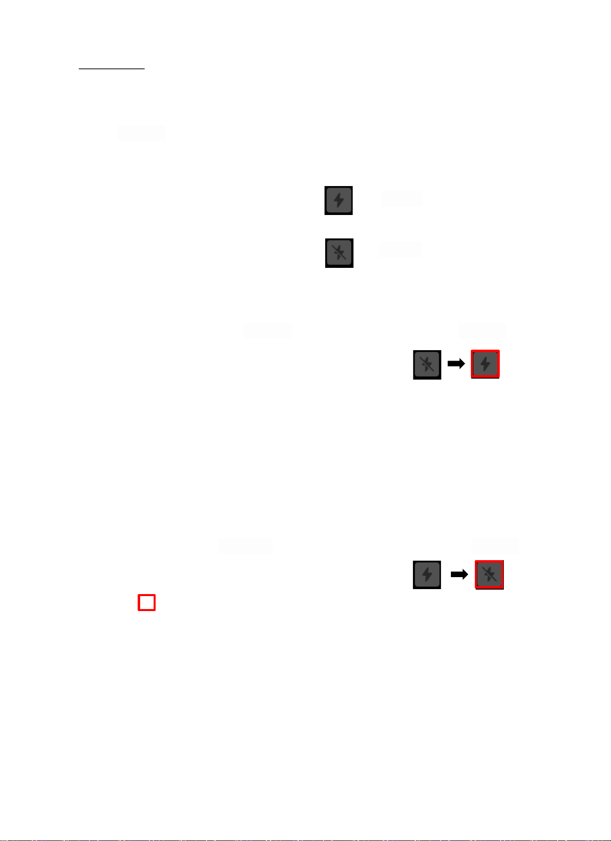
VII. How to Operate Light Operation
The light icon(object) the top of the screen allows you to activate two lights mounted on the front of the
product.
1) Light ON
When the light is off and you press the icon(object), the light turns on immediately and the icon(object) is
changed.
2) Light OFF
When the light is on, pressing the icon(object) immediately turns off the light and changes the icon(object).
Light ON
Light OFF
Find Quality Products Online at: [email protected]
www.GlobalTestSupply.com
Page 11

BATCAM 2.0
10
Component Description
I. Power Device
AC/DC Adaptor(12 V, 3.5 A) + Power Cable
Power supply and internal battery charging for BATCAM 2.0
and a dedicated LEMO connector for connection between
adapter and cable. Power units are recommended to use the
power units included in the product.
II. User Manual
BATCAM 2.0 User Manual
This is a manual for BATCAM 2.0 users and provides a variety of
use the product.
III. Portable Hard Case
BATCAM 2.0 Portable Hard Case
Waterproof case for storing or carrying BATCAM 2.0 product
and components. It is recommended that you use it for storage
and movement of product.
Find Quality Products Online at: [email protected]
www.GlobalTestSupply.com
Page 12

BATCAM 2.0
11
IV. Hand Strap
On the right side of BATCAM 2.0 there is a hand strap which allows user to hold the product when measuring
with hand as shown below. Care must be taken not to drop the product when using straps.
BATCAM 2.0 Hard Case Interior Appearance and Storage
Find Quality Products Online at: [email protected]
www.GlobalTestSupply.com
Page 13
BATCAM 2.0
12
Software
I. Main Screen(User Interface)
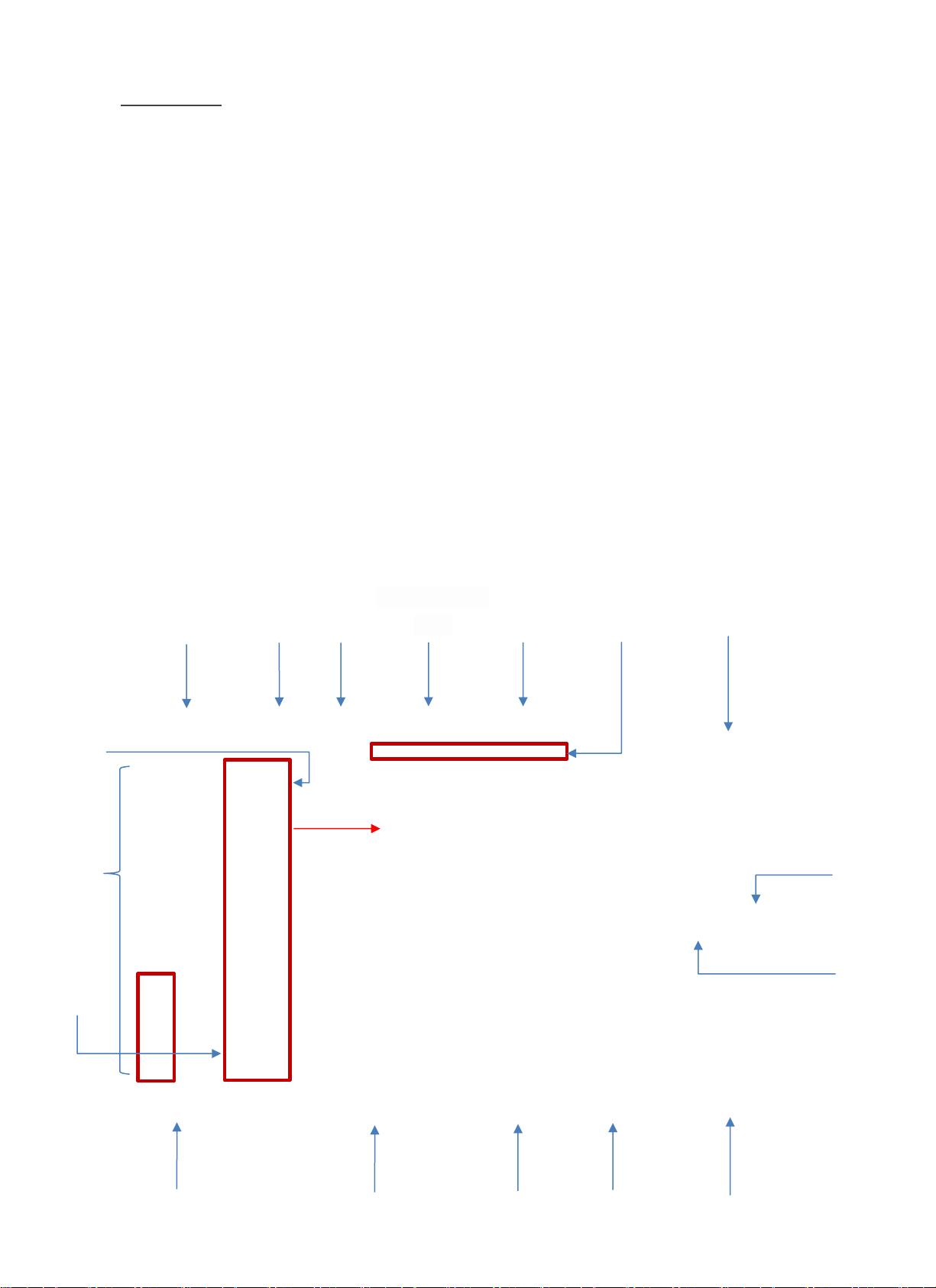
When the BATCAM 2.0 software runs, it appears as shown on the main screen below. Users can set and view
various measurements on the main screen without having to connect to a PC.
Settings consist of beamforming settings, measurement environments settings and other settings. First, the
beamforming setting is for beam power, which shows the value of the size of the noise being measured in a
rainbow colored chart. These settings include threshold(display reference value), image range, and image
average settings. The measurement environment settings set the appropriate values for the characteristics
and conditions of the noise to be measured, including measurement mode, distance between source and
BATCAM 2.0, and gain settings. Other settings include language/time zone, hide icon(object), measurement
file USB transfer, and gallery(check/delete measurement file) settings as settings for user convenience and
measurement efficiency. The user can also estimate the degree of leakage occurring by the leakage quantity
icon(object) at the top. Checking the internal memory and battery status is also availiable.
Measurement
Mode
Leakage
Quantity
Hide Icon(Object)
Max. Beam Power
Value
Light
Battery Status
Measurment File
USB Transfer
Gallery
Image Average
Gain
※ When 'Custom' mode is selected,
measurement frequency range can be set
by user
Min.
Measurement
Frequency
Max.
Measurement
Frequency
Image Range
Language
/Timezone
Distance
Internal Memory
Status
Threshold
Find Quality Products Online at: [email protected]
www.GlobalTestSupply.com
Page 14
BATCAM 2.0
13
II. Icon(Object) and Function Description
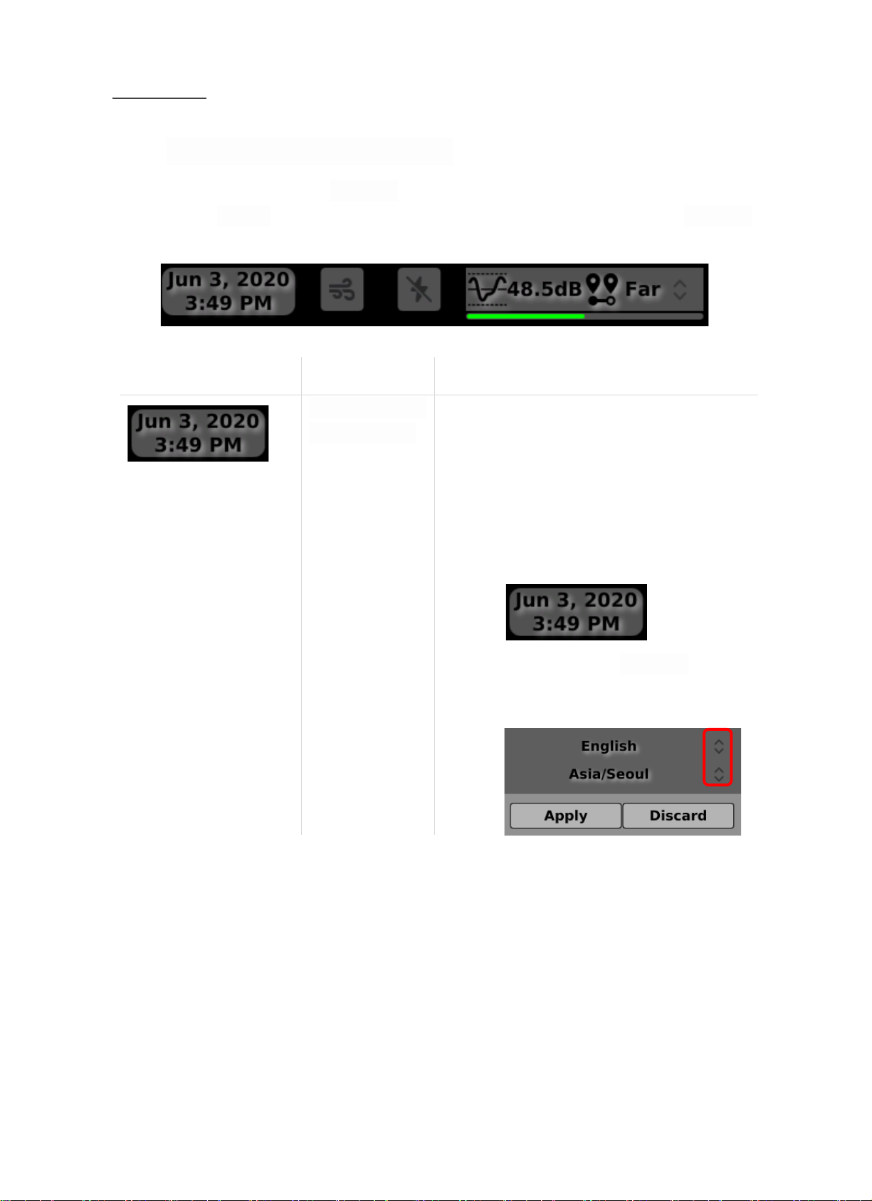
Provide a detailed description of the icon(object) and functions displayed on the main screen. At the top, a
total of four icons(objects) will be shown, and the functions, definitions, and descriptions of each icon(object)
are shown in the table below.
Icon(Object)
Function
Description
Language/Timezone
Check and Setting
This icon(object) indicates the current date/time. In
addition, you can change the language of use as well
as the time zone for each country by pressing and
holding the icon(object). The method of change is as
follows.
1.
Press and hold the icon(object)
2.
Find Quality Products Online at: [email protected]
www.GlobalTestSupply.com
Page 15
BATCAM 2.0
14
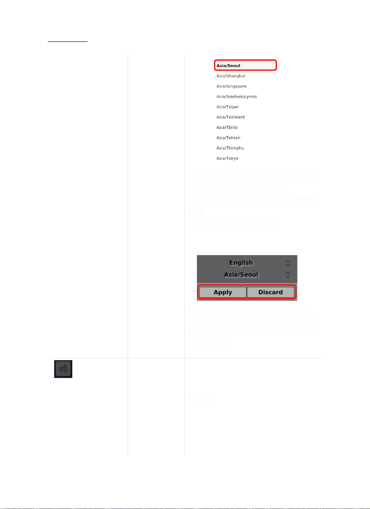
Touch the arrow in the red box to select the
language/time zone you want to change
*Language: Support for Korean, English, Chinese and
French
*Time zone: Support for all countries
3.
Press 'Apply' button to select language/time zone
Applies and when the ‘Discard’ button is pressed, the
language/time change will be invalidated(pop-up
window closed)
Leakage Estimation
Check Index
This icon(object) indicates the amount of Leakage
that is occurring. Depending on the amount of
leakage, it will be changed to a suitable number
icon(object), and the criteria for distinguishing
icons(objects) are as follows.
Less than 200 cc/m
Find Quality Products Online at: [email protected]
www.GlobalTestSupply.com
Page 16
BATCAM 2.0
15
Excess 200 Less than 400 cc/m
Excess 400 ~ Less than 600 cc/m
Excess 600 ~ Less than 800 cc/m
More than 800 cc/m
Light ON/OFF
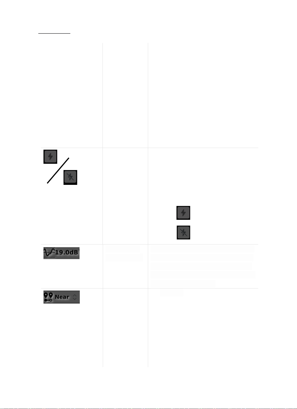
User can turn on or off the light mounted on the
front of the hardware with this icon(object).
When pressing the icon(object) while the light is on,
the light will be off.
When pressing the icon(object) while the light is off,
the light will be on.
Light ON
Light OFF
Maximum Beam
Power Value Check
This icon(object) shows the maximum beam power
value of the noise being measured. Beam Power is
the color scheme in the form of a rainbow on the
measurement screen, which indicates the amount of
sound pressure being measured.
Distance Setting
This icon(object), allows the user to set the distance
between the noise source or target being measured
and the ultrasonic camera.
For accurate measurements, it is recommended that
you set the distance before measuring. There is a
total of three options and the selection criteria are as
follows:
Near Distance(Near): If the measured target is
Find Quality Products Online at: [email protected]
www.GlobalTestSupply.com
Page 17
BATCAM 2.0
16
within 5 m
Far Distance(Far): If the measured target is more
than 5 m away
Automatic Distance Setting(Auto): When more
precise measurements are required using
distance sensor values(only possible if the
distance between the source and BATCAM 2.0 is
within 3 m)
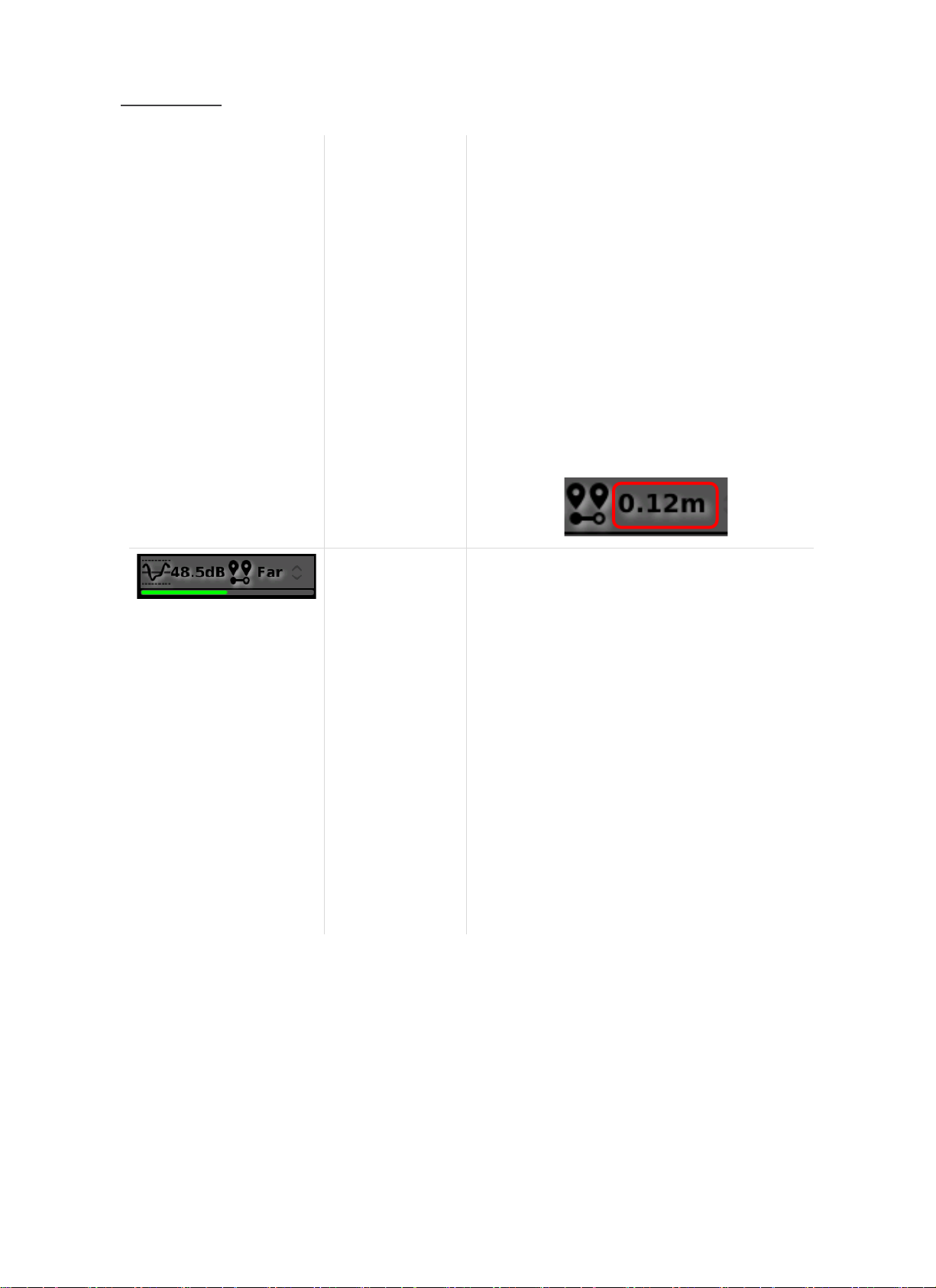
When the Auto option is selected, the distance
between the noise source and the ultrasonic camera
can be viewed in real time(within 3 m).
Ex)
Internal Memory
Status Check
The user can check the internal memory status of
BATCAM 2.0 under the 'maximum beam power value'
and 'distance' icon(object). It is divided into three
colors: green, orange and red, and the criteria for
classification are as follows:
For your information, the internal memory capacity
of BATCAM 2.0 is about 53 GB.
Green: Used less than 98 % internal memory
Orange: Used more than 98 % of internal memory
less than 99 %
Red: Used more than 99 % of internal memory less
than 100 % – Saving vido is not available
Find Quality Products Online at: [email protected]
www.GlobalTestSupply.com
Page 18
BATCAM 2.0
17
Next, icons(objects) on the right side of the main screen. There are four icons(objects) on the right side of
the screen, each icon's(object’s) function, definition, and description are shown in the table below.
Icon(Object)
Function
Description
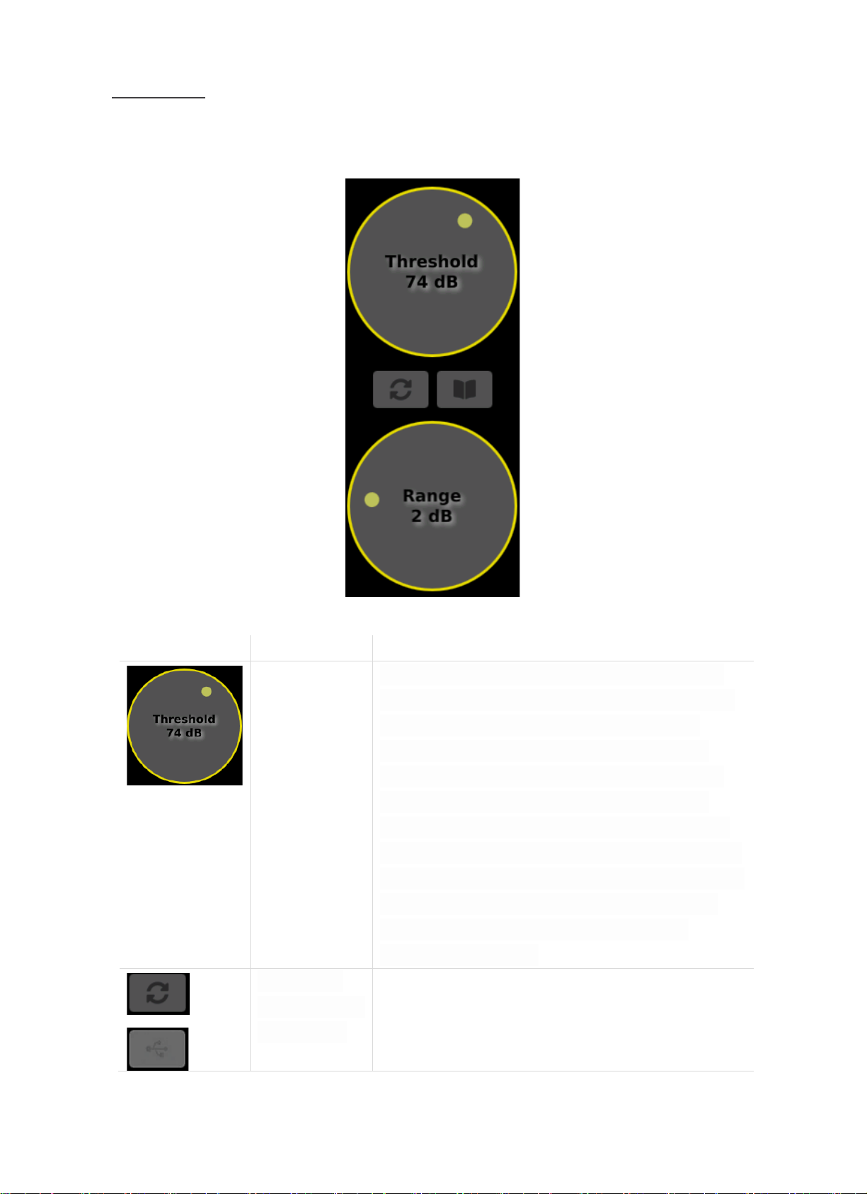
Threshold
(Display Reference
Value) Setting
The beampower shown on the screen depends on the set
reference value. This means that the noise you are trying to
measure must be greater than or equal to the display
reference value before the beam power appears on the
screen. Inversely, if the noise is less than the set reference
value, the screen does not display the beam power. For
accurate measurements, it is recommended that you check
the display reference value settings before the measurement,
depending on your measurement environment. The reference
value can be set from 0 dB to 120 dB, depending on the
characteristics of the noise being measured and the
measurement environment.
Measurement
File(Image/Video)
Transfer to USB
Mount the USB memory device in a USB port located on the
left side of BATCAM 2.0(if user is viewing the screen), and press
this icon(object) to copy the measured pictures and videos to
the USB memory device. If the USB memory device is not
Find Quality Products Online at: [email protected]
www.GlobalTestSupply.com
Page 19
BATCAM 2.0
18
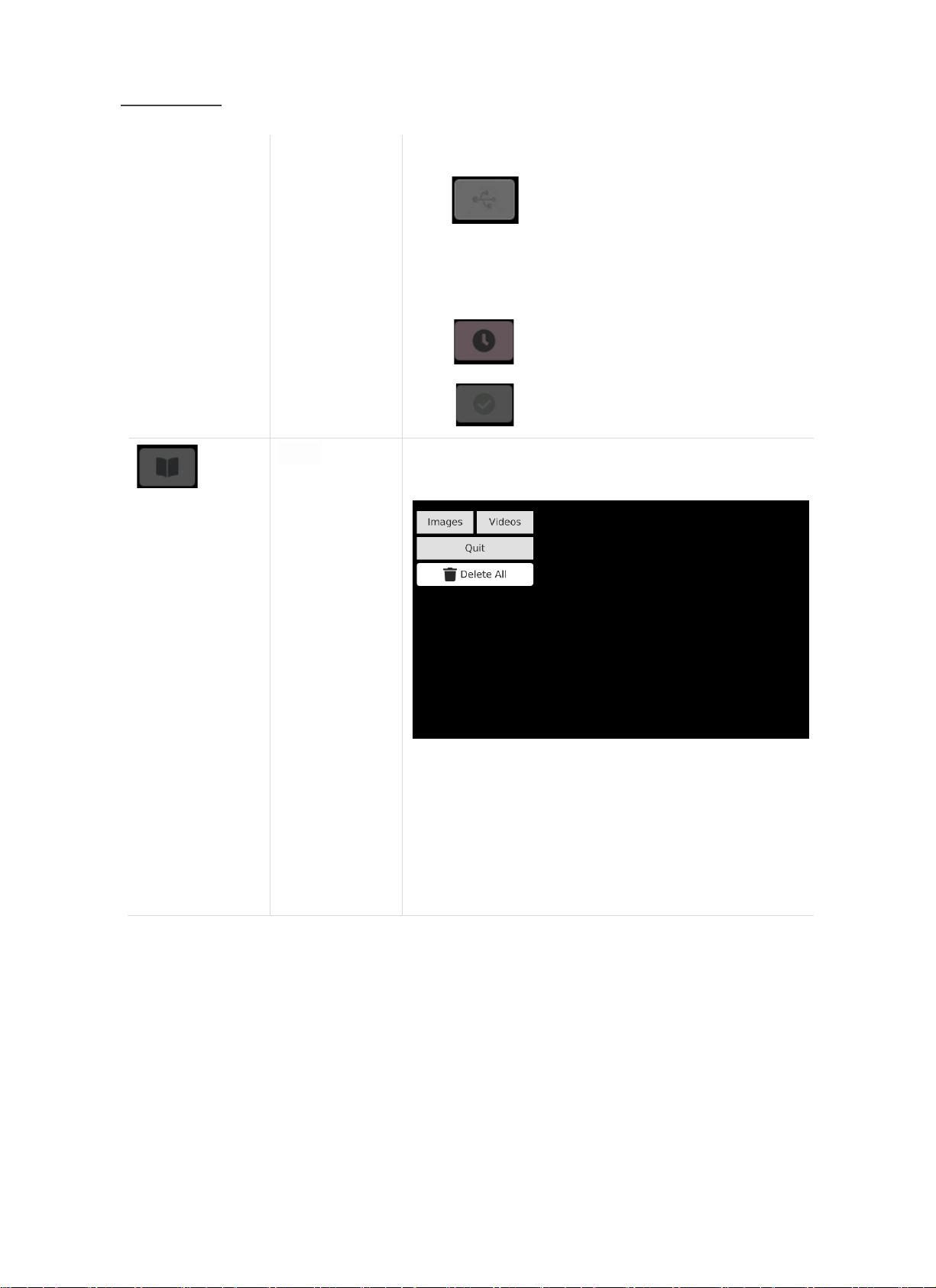
connected, it will be shown below.
When you connect the USB memory device and start
transferring files, the icons(objects) below appear sequentially.
BATCAM 2.0 -> USB File Transfer in Progress
BATCAM 2.0 -> USB File Transfer Completed
Gallery
(Check/Delete
measurement file)
Press this icon(object) to check or delete the measurement
file(image/video) of BATCAM 2.0.
Press 'Images' or 'Videos' to see or delete the measurment
images or videos.
Press 'Quit' to return to the main screen, and press 'Delete All'
to delete all files.
To delete only one file, select the file and press the 'Delete'
button on the bottom right.
USB Memory Device is not connected
Find Quality Products Online at: [email protected]
www.GlobalTestSupply.com
Page 20

BATCAM 2.0
19
User can copy the selected file to the USB memory device by
pressing the button on the top right.
Also, the measured image shows the information below.
(This will not be recorded in the measured video.)
Date/time at time of measurement
Maximum beam power value(dB) at time of measurement
Display Base(dB) at time of measurement
Image range value at time of measurement(dB)
Amplification value at time of measurement(dB)
Frequency band(kHz) set at time of measurement
Image mean setting at time of measurement
Estimated amount of leakage at time of measurement(LFE)
index value
Find Quality Products Online at: [email protected]
www.GlobalTestSupply.com
Page 21
BATCAM 2.0
20
Image Range
Setting
This function sets the range of the minimum(blue) and
maximum(red) values of the beam power displayed on the
screen. This means that the width of the beam power can be
adjusted. User can set a minimum of 0 dB(full range) to a
maximum of 10 dB, and the higher the value, the greater the
width of the beam power.
If the image range is set to 0 dB, beamforming is applied
throughout the screen(Full Range).
※ For a detailed description of the display threshold and image range, refer to the 'Beam Forming
Setting' section.
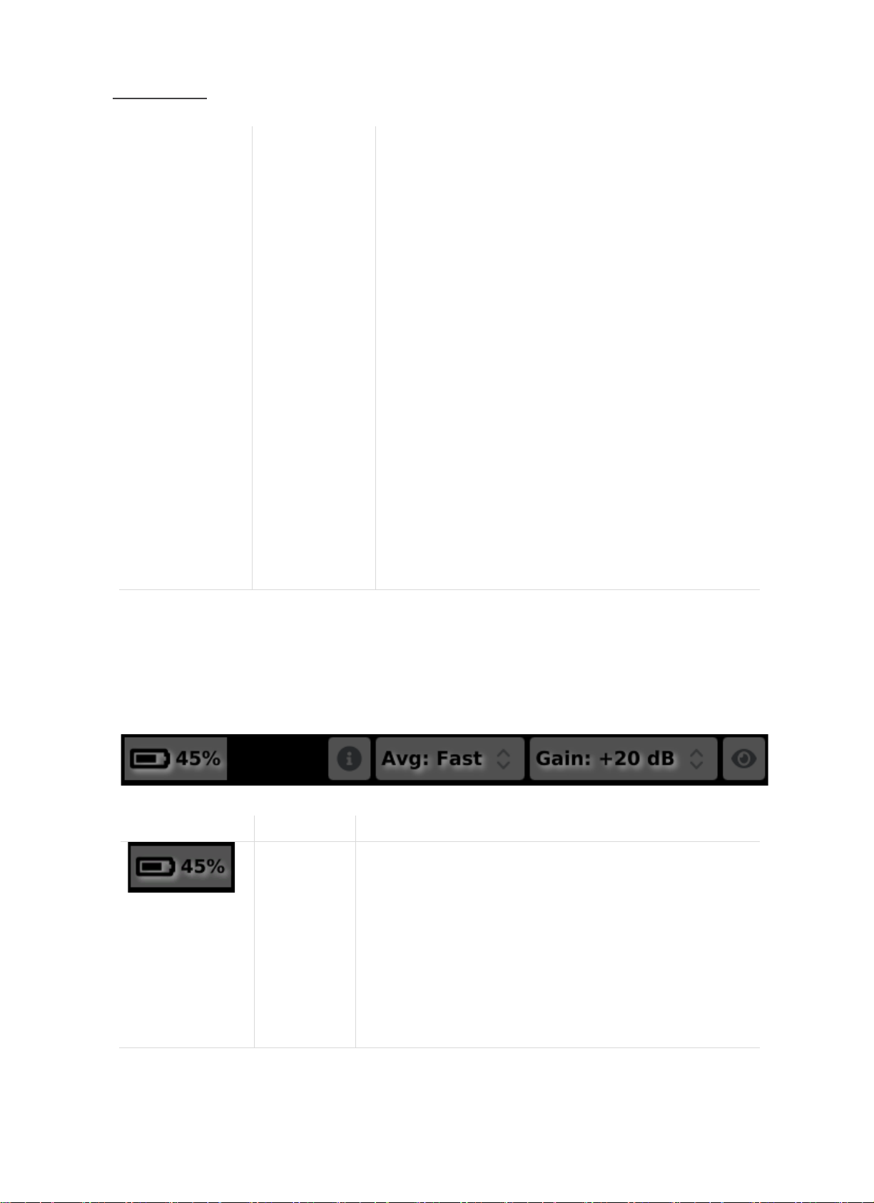
At the bottom of the main screen, there are five icons(objects) shown below. The function, definition and
description of each icon(object) are as below.
Icon(Object)
Function
Description
Battery Status
Check
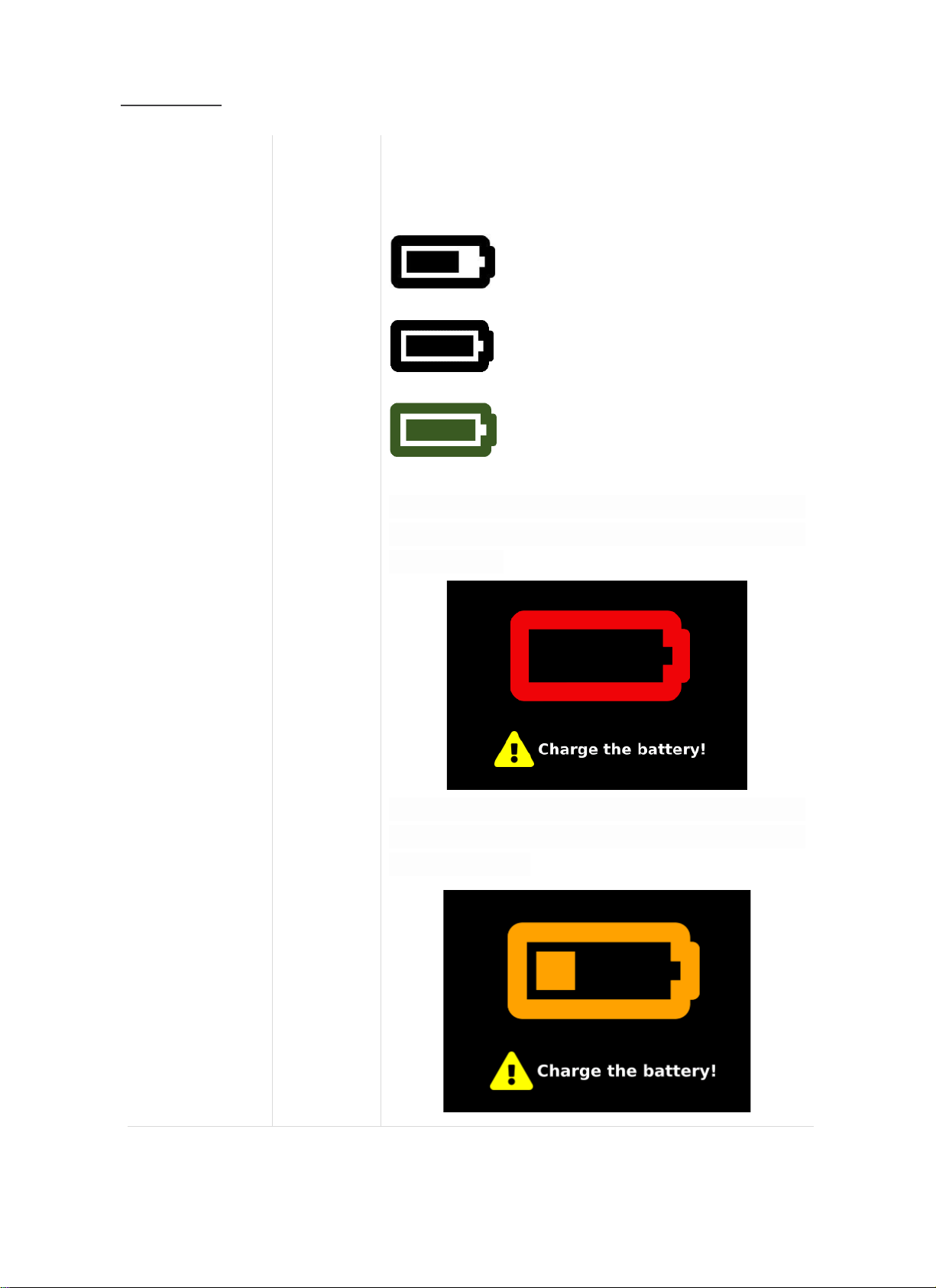
This icon(object) allows the user to check the current battery status.
The battery status is expressed in four images below, depending
on the range. When the battery is fully charged, the BATCAM 2.0
operates smoothly for about four hours.
Battery Capacity 2 ~ 9 %
Find Quality Products Online at: [email protected]
www.GlobalTestSupply.com
Page 22
BATCAM 2.0
21
Battery Capacity 10 ~ 29 %
Battery Capacity 30 ~ 72 %
Battery Capacity 73 ~ 97 %
Battery Capacity 98 ~ 100 % (Full Charged)
If the battery is below 1 %, a warning message below will appear.
If this warning message appears, connect the BATCAM 2.0 power
unit and charge it.
Once the power supply has stabilized, the screen below will be
switched to. If the battery is charged more than 15 % then BATCAM
2.0 can be used again.
Find Quality Products Online at: [email protected]
www.GlobalTestSupply.com
Page 23
BATCAM 2.0
22
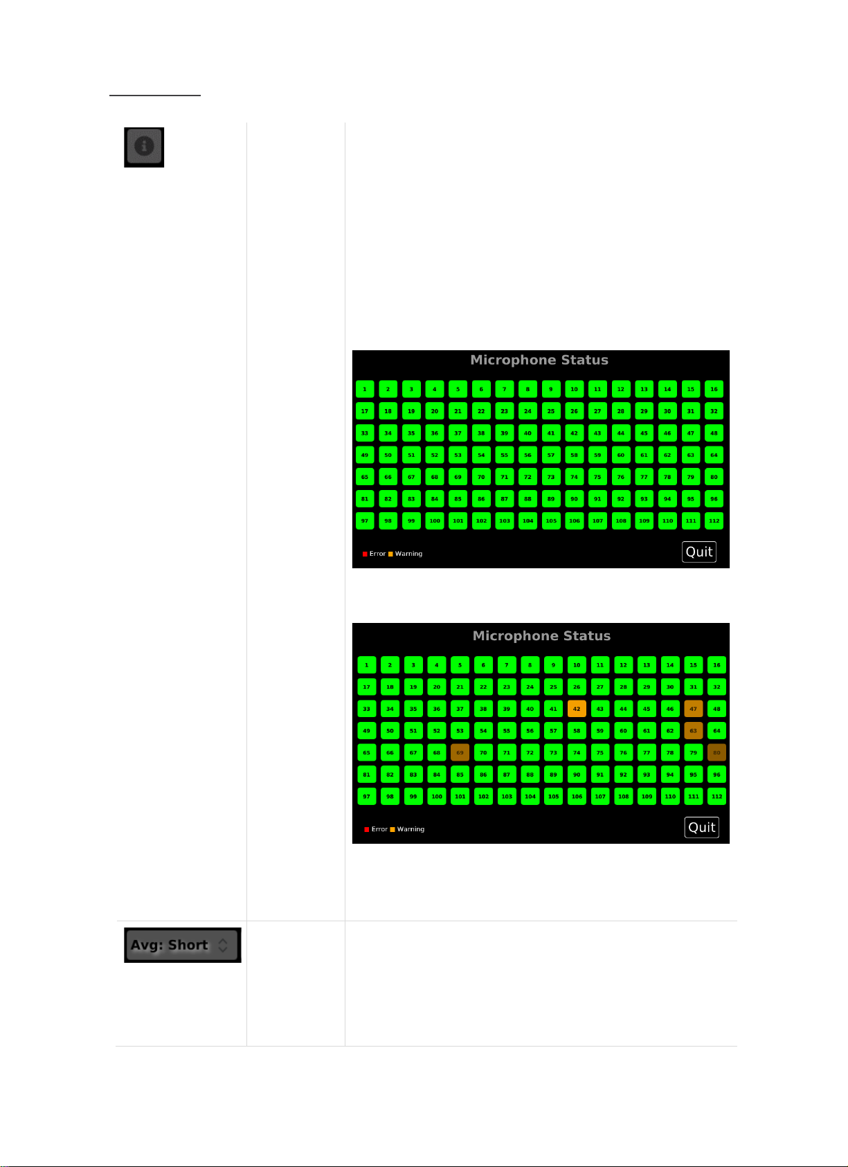
Microphone
Status Check
*Only Visible
In Audible
Mode
Press this icon(object) to check the operation of 112 microphones
mounted on the front of BATCAM 2.0 (only visible in audible mode).
The colors of each icon(object) by operating state are as follows:
Green: Normal
Orange: Dangerous
ex) When the microphone is blocked by alien substances
Red: Abnormal
Ex) All 112 microphones are normal
Ex) No 42,47,63,69,80 microphones are blocked
by alien substances
Image
Average
Setting
Image average is another way of setting up the beam power image
on the screen. Depending on the type or characteristics of the
noise, user can set the appropriate image average. There are two
options in total and the selection criteria are as follows:
Find Quality Products Online at: [email protected]
www.GlobalTestSupply.com
Page 24
BATCAM 2.0
23
Fast: average update of normal speed
Slow: Update slowly with slightly longer average values
Slow settings can be updated slowly for fast changing sound
signals to determine the location of the noise source. For a detailed
description of the image average, see 'Beamforming Setting'.
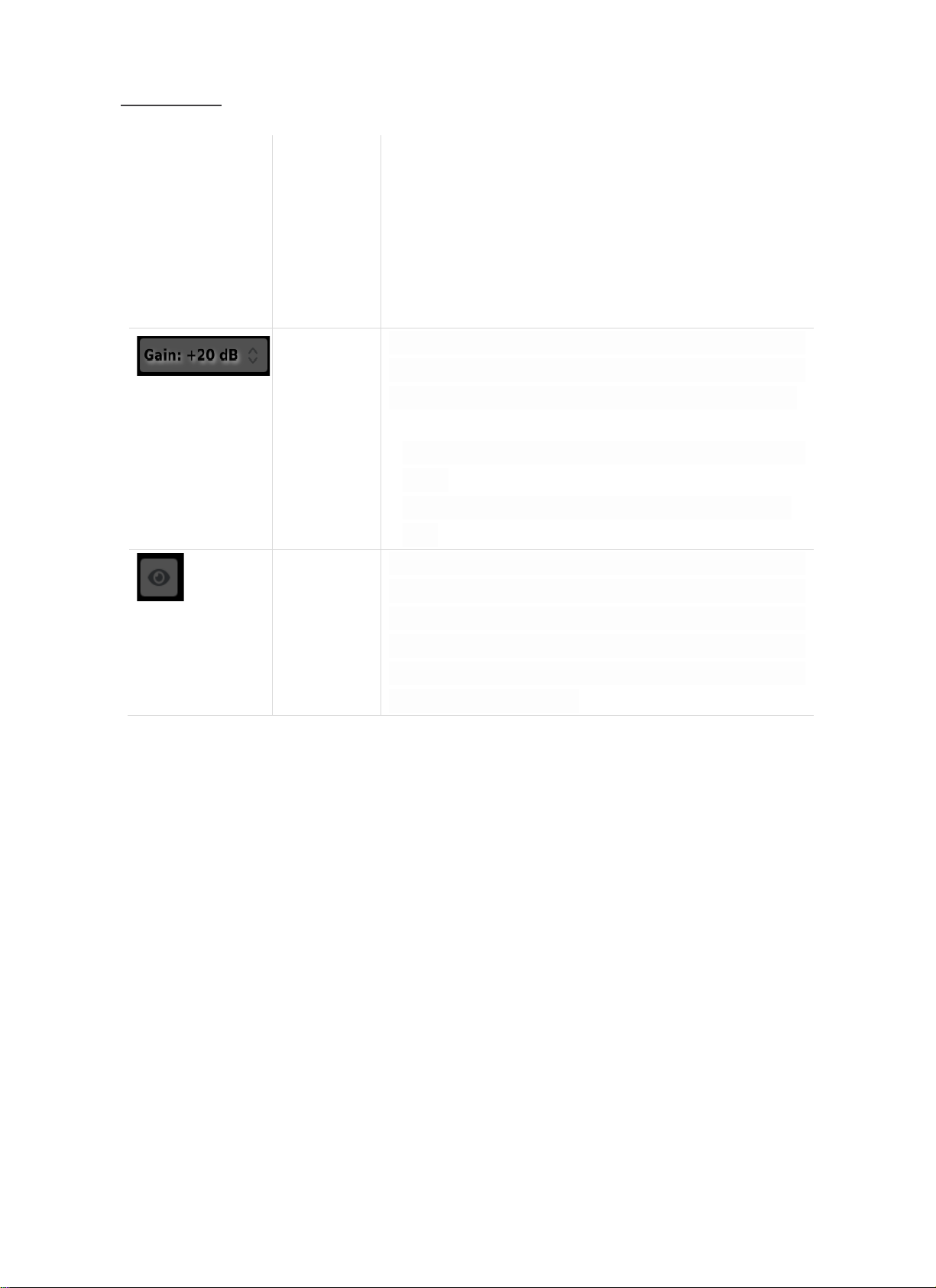
Gain Setting
Depending on the amount of noise, user can set the appropriate
gain value. User can select from 0, +10, +20, or +30 dB, and can
apply the appropriate value depending on the size of the noise.
A reasonable gain value for normal-sized noise measurements:
+20 dB
*The smaller the sound, the better it is to increase the gain
value.
Hide
Icon(Object)
This icon(object) provides a clearer picture of the screen being
measured by hiding the objects 'Threshold', 'Image Range',
'Measurment File USB Transfer'and 'Gallery' on the right side of the
screen. If user is using custom mode, the frequency setting slide
will be also hidden. Touch the icon (object) one more time to
release the hidden processing.
Find Quality Products Online at: [email protected]
www.GlobalTestSupply.com
Page 25
BATCAM 2.0
24
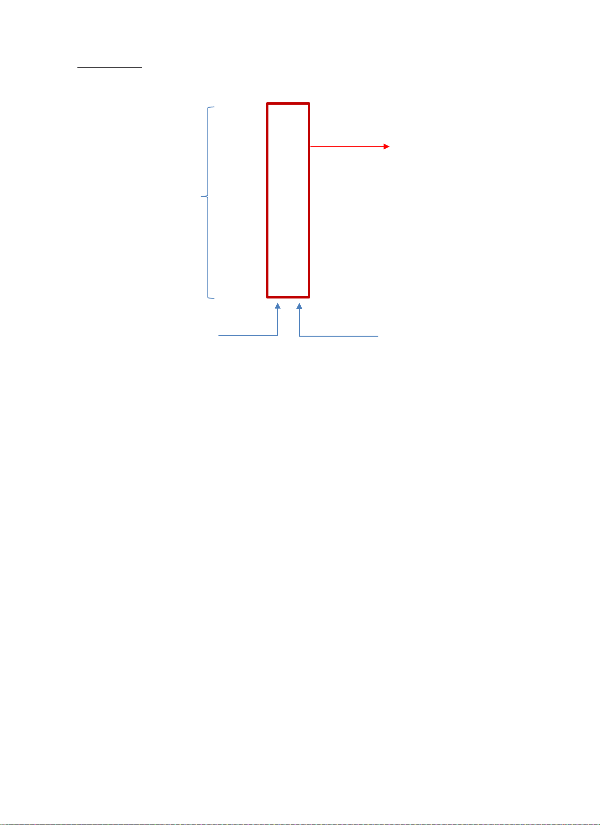
Finally, on the left side of the main screen, there is an area for simple selection of measurement mode or
for the user to set the measurement frequency area directly. It is configured in the 'ultrasonic', 'audible',
and 'custom' mode, each of which is described as follows:
The 'ultrasonic' mode automatically sets the band pass filter at 25 kHz to 40 kHz for the ultrasonic
frequency area and is suitable for measuring gas/air leaks and electrical discharge. When 'Audible' mode
is selected, the band pass filter is automatically set from 4 kHz to 20 kHz for the audible frequency area
and is suitable for measuring human audible noise and joints.
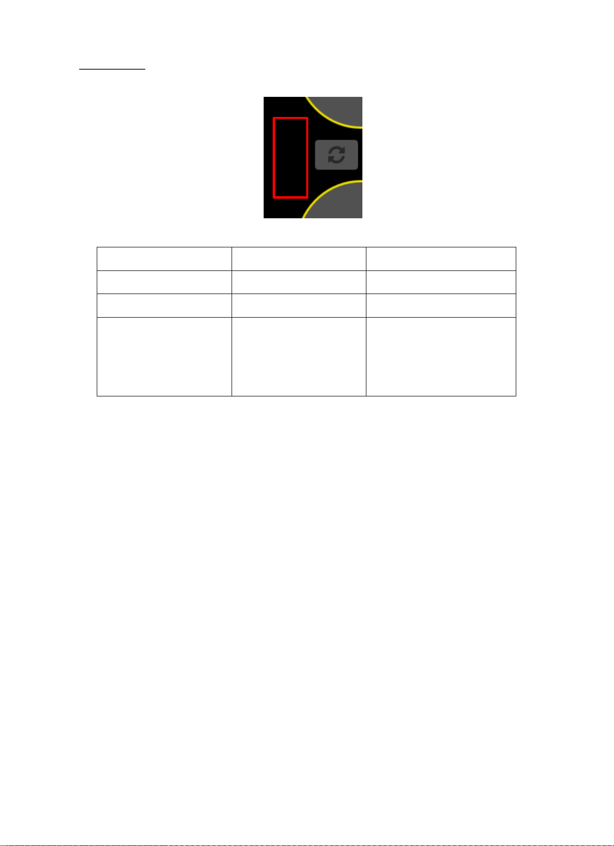
User can listen to the sound sources measured in either 'ultrasonic' or 'audible' mode, when user can
adjust the volume of the audio output. User can adjust the volume adjustment number by scrolling up
and down the empty area(the red display area below) on the left side of the 'Measurment File USB
Transfer' icon(object). The volume can be adjusted from 0 to 20. Volume control is not possible if 'Hide
Icon(Object)' has been activated.
Maximum
Measurement Frequency(kHz)
Measurement
Mode
Minimum
Measurement Frequency(kHz)
※ When select ‘Custom’ mode, measurement
frequency range can be set up by the user
Find Quality Products Online at: [email protected]
www.GlobalTestSupply.com
Page 26
BATCAM 2.0
25
‘
Measurement Mode
Frequency Range
Remark
Ultrasonic
25 kHz ~ 40 kHz
Auto Set
Audible
4 kHz ~ 20 kHz
Auto Set
Custom
Set up by user
When 'Custom' mode is selected,
measurement frequency range
can be set by user
Find Quality Products Online at: [email protected]
www.GlobalTestSupply.com
Page 27

BATCAM 2.0
26
III. Beam Forming Setting
The Beam forming setting sets the various values of beam power that show the characteristics of the
measured noise in rainbow-shaped color scheme, including the display reference, image range, and image
average setting. The beam power visually shows the amount of sound pressure produced in the direction
of measurement of the ultrasonic camera. The beam power displayed on the screen can show both the size
and distribution of the noise generated, but it usually depends on the display reference setting value. Also,
the beam power, calculated as 25 frames per second, will be visible on the screen at a resolution of 640 x
480.
1) Threshold(Display Reference Value)
The beam power that appears on the screen depends on the set display threshold. This means that the noise
you are trying to measure must be greater than or equal to the Threshold before the beam power appears
on the screen. Conversely, if the noise is less than the set display threshold, beam power will not be
displayed on the screen. For accurate measurements, it is recommended that you set the Threshold before
measurements, depending on your measurement environment. The display reference value can be set from a
minimum of 0 dB to a maximum of 120 dB, depending on the nature of the noise you want to measure and
the measurement environment.
The Threshold setting is set as the minimum value of the noise source you want to measure, and only above
the set value is displayed on the screen. Values below the setting are not displayed on the screen. The range
of images is expressed in color for the noise source being measured, as shown in the graph above, with the
minimum and maximum values being expressed in the image portion as values greater than the threshold
value. The color scheme shown on the screen represents the level of sound pressure from maximum(Red) to
minimum (blue).
2) Image Range
This function sets the range of the minimum(Blue) and maximum(Red) values displayed on the screen. This
means that you can adjust the width of the beam power displayed. A minimum of 0 to 10 dB can be set,
and the higher the value, the greater the width of the beam power.
Find Quality Products Online at: [email protected]
www.GlobalTestSupply.com
Page 28

BATCAM 2.0
27
The range of images varies with the maximum value, such
as the sound pressure changing in the left graph, with the
minimum value changing with the maximum value.
If you raise threshold, it affects the beam power displayed
on the screen regardless of the setting value of the image
range. For example, if the minimum setting value for the
image range is less than the display reference value, as
shown in the graph on the left, then the display reference
value is set to the minimum value and displayed on the
screen.
3) Image Average
This function sets the way the beam power image is displayed on the screen (beam power image average).
Depending on the type or characteristics of the noise, the user can set the appropriate average.
If there is no image average, the current noise is immediately displayed on
the screen. If you look at the graph on the left, the current noise is
indicated by a black line, and an orange dotted line shows the threshold.
The screen shows the part displayed by the rainbow colored chart, and
updates are made immediately for each frame that is processed. In these
settings, it is difficult to visually identify short-lived sounds.
Exponential Average: Fast / Quick Response
This feature allows you to see changes in sound by applying different
average parameters depending on your selection options. Typically, you
can set it to Fast Response to measure it, and user can change it to slow
response so that it can be updated slowly.
Find Quality Products Online at: [email protected]
www.GlobalTestSupply.com
Page 29

BATCAM 2.0
28
IV. Additional Setting
1) Software update
The software information in BATCAM 2.0 currently in use is displayed in the upper right corner of the main
screen.
To update to the latest software in BATCAM 2.0, you can proceed in sequence below. The update will take
up to 5 minutes to complete, and be careful that an error may occur if BATCAM 2.0 is turned off while the
update is in progress. Update files can be obtained at a later notice(E-mail or Website).
*BATCAM 2.0 Software Update Procedure
① Connecting USB Memory Devices to a PC or laptop
② Creates a folder named 'BATCAMV2_UPDATE' inside the USB memory device. All must be
capitalized in English and does not matter if there is a folder with a different name inside the USB
③ Download latest software files to your PC or laptop. The file extension is .mender
④ Copies downloaded files into the 'BATCAMV2_UPDATE' folder created in 2.
The downloaded update file name must be in the following structure
└-- BATCAMV2_UPDATE
└-- SMI-BATCAMV2-v0.0.0-signed-2020xxxxxxxxxx.mender
(v0.0.0 : Firmware version, xxxxxxxxxx : Date+Time Format)
Update in progress for BATCAM 2.0
⑤ Safely remove USB memory device from PC or laptop
⑥ Connect USB memory device to BATCAM 2.0 hardware USB port
⑦ When USB memory device is connected, updates are automatically made and progress can be
checked on the screen. Up to 5 minutes for update to complete
⑧ Update completed and all procedures completed when BATCAM 2.0 is rebooted
Find Quality Products Online at: [email protected]
www.GlobalTestSupply.com
Page 30

BATCAM 2.0
29
V. Product Management and A/S
1) Product management
There are 112 microphone sensors in front of BATCAM 2.0. If the microphone is dirty or clogged with
debris, etc., it can be cleaned at a distance of approximately 30cm under low air pressure from the
compressed air injector. Do not spray too much pressure with air pressure. Also, keep the product in its
case when not in use.
2) A/S
① Free A/S: Free A/S for one year from the date the customer receives the product, provided that the
following is a paid A/S.
② Paid A/S:
✓ In case the warranty period for free of charge has expired
✓ Defects caused by customer negligence or careless handling
✓ Defects caused by natural disasters, accidents, disasters, etc.
✓ Defects caused by external factors other than defects in quality or performance of the main body
of the product.
Find Quality Products Online at: [email protected]
www.GlobalTestSupply.com
Page 31

BATCAM 2.0
30
Product Specification
Item
Specification
Microphone Array
Microphone Type
Number of Microphones
Digital MEMS
112 EA
Measurement Frequency Range
2 k ~ 48 kHz
Microphone Sensitivity
-41 dBFS
Signal to Noise Ratio (SNR)
66 dB(A)
Camera View Angle
Horizontal 66 degree, Vertical 54 degree
Measuring Distance
0.3 m ~ 50 m(Vary depending on the
measurement environment)
Display Type
5” Color LCD
Data Acquisition and Processing
Sampling Rate
96 k S/s
Image Frame Rate
25 FPS
Image Resolution
640 x 480
Internal Memory
53 GB(About 25 MB for 5 minutes, 7 days for
continuous video storage)
Measurement Circumstances
Operating Temperature
Operating Humidity
-20 ~ 50 °C
10 ~ 85 %
Internal Batterypack
Battery Type
Battery Capacity
Battery Operating Time
Lithium ion battery pack
49.5 Wh
4 hours
Components and other specifications
Item
Specification
External Batterypack
Battery Type
Battery Quantity
(TBD)
USB
Memory Type / Support Format
2.0 / FAT 32
Find Quality Products Online at: [email protected]
www.GlobalTestSupply.com
Page 32

BATCAM 2.0
31
Product Certification
I. Electromagnetic Compatibility
This product meets the requirements of the following EMC standards for measurement, control and sensitive
electronic equipment used in laboratories. EN 55032:2015/AC:2016
✓ EN 55035:2017
✓ EN 61000-3-2:2014
✓ EN 61000-3-3:2013
II. FCC Compliance
This product meets the essential requirements of the applicable U.S. Directive as follows:
✓ FCC Part 15 Subpart B, Class A
III. CE Compliance
This product meets the essential requirements of the applicable European Directive as follows:
✓ 2004/108/EC; Electromagnetic Compatibility Directive(EMC)
IV. KC Compliance
This product proves that it has been registered in accordance with paragraph 2-3 of Article 58 of the Radio
Wave Act.(The Clause 3, Article 58-2 of Radio Waves Art.)
V. Battery
This product uses lithium ion batteries.
Do not use the product in environments where it can be wet, wet, or corroded. Do not store or place the
product in or near the source of heat in a high temperature, strong direct sunlight, microwave or pressurized
container. Also, do not expose to temperatures above 122 °F / 50 °C. Failure to follow these instructions may
result in acid leak, heat, explosion or ignition, causing injury and damage. Do not drill, open or disassemble
the battery. If the battery is in contact with the leaked fluid, rinse it with water sufficiently and seek a
Find Quality Products Online at: [email protected]
www.GlobalTestSupply.com
Page 33

BATCAM 2.0
32
consultation with a steam doctor. Charging does not occur at low temperatures(32 °F / 0 °C or below) or
high temperatures(113 °F / 45 °C or above).
※CAUTION: If the battery is not replaced with the correct type, there is a risk of explosion.
Do not attempt to remove or remove a battery that the user cannot replace. If there is a problem with the
battery,
The batteries contained in this product must be disposed of in accordance with local laws and regulations.
✓ IEC 62133:2012
✓ EN.62133:2013
✓ UN 38.3(ST/SG/AC.10/11/Rev.6/Amend.1
Find Quality Products Online at: [email protected]
www.GlobalTestSupply.com
Page 34

BATCAM 2.0
33
Precautions
※ Precautions before use ※
Be sure to follow the instructions for operation of the device.
Install the product in a stable and horizontal position.
If the product is on and stored in a case, there is a risk of product damage and fire.
Do not allow vibration or shock to be transmitted directly to the product.
Do not drop or cause any impact.
Be careful not to step on the power cable or trip the object during charging. An open circuit in
the cable may cause a product to fail.
Do not store in hot and humid places, places with a lot of direct sunlight, or places with a lot of
dust.
Do not store chemicals in the storage area or in the place where
Do not use this device outside of the range of temperature used.(appropriate temperature range:
-20 C to 50°C)
Do not use it in places where there are strong magnets, power meters, etc.
If you are connecting or disconnecting each cable or cord from the main body, do not grab the
part of the cable, but hold the part of the plug and connect or disconnect it.
Do not allow foreign substances to enter the product between the surface of the microphone or
the heat shield.
Do not disassemble or modify without approval from the manufacturer.
In the event of a failure or damage to the main body or accessories, specify the details of the
failure or damage and contact the dealer or our service representative.
Dispose of this product in accordance with the national or local government ordinance.
Find Quality Products Online at: [email protected]
www.GlobalTestSupply.com
 Loading...