

FRANÇAIS
NEDERLANDS
DEUTSCH
NORSK
SLOVENSKI
SVENSKA
SUOMI
DANSK
ITALIANO
ENGLISH
ESPAÑOL
INSTALLATION / USAGE / ENTRETIEN - FR
INSTALLATIE / GEBRUIK / ONDERHOUD - NL
INSTALLATION / GEBRAUCH / WARTUNG - DE
ASENNUS / KÄYTTÖ / HUOLTO - FI
INSTALLATION / ANVÄNDNING / UNDERHÅLL - SE
INSTALLASJON / BRUK / VEDLIKEHOLD - NO
INSTALACIJA / UPOR ABA / VZDR ŽEVANJE - SI
INSTALLATION / USE / MAINTENANCE - GB
INSTALLA ZIONE / USO / MANUTENZIONE - IT
INSTALLATION / BRUG / VEDLIGEHOLDELSE - DK
INSTALACIÓN / USO / MANUTENCIÓN - ES
INSTALAÇÃO / UTILIZAÇÃO / MANUTENÇÃO - PT
PORTUGUÊS
7003 - 7023 - 7103 - 7123 - 8103 VD - 8103 VDM - 8123 VD - 8123 VDM
8203 - 8203 M - 8223 - 8223 M - MO8302 - MO8303 - MO8322 - MO8323
MO8342 - MO8362 - MO8801D - MO8801S - MO8821D - MO8821S
MO9122 - MO9202D - MO9202S - MO9222D - MO9222S - PI7203 - PI7223 - PI7703
PI7723 - PI8002 - PI8003 - PI8022 - PI8023 - PI8042 - PI8043 - PI8062 - PI8063
PI8403 - PI8423 - PI8443 - PI8463 - PI8502 - PI8503 - PI8522 - PI8523 - PI8542
PI8543 - PI8562 - PI8563 - PI8621A - PI8621R - PI8621S - PI8802D - PI8802S
PI8822D - PI8822S - PI8842D - PI8842S - PI8862D - PI8862S - PI9003 - PI9023
12
ENGLISH
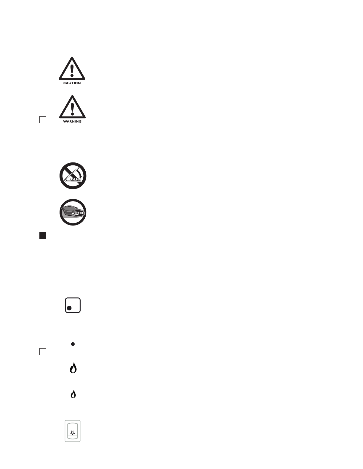
SYMBOLS
WARNINGS AND SAFETY SYMBOLS
The safety symbols utilised identify possible hazards to users.
Always respect all safety warnings identified with these symbols:
INDEX
INSTALLATION 13
SAFETY WARNINGS 13
CABINET APERTURE 13
CONNECTING TO GAS SUPPLY 14
WIRING- CONNECTING TO ELECTRICITY SUPPLY 15
FIXTURE 15
USE 16
WARNINGS 16
CONTROLS 16
BURNERS: 17
HOB: 18
SELECTING BURNER 18
ELECTRONIC IGNITION HOB (DEPENDING ON MODEL) 18
MANUAL IGNITION HOB 18
HOB FLAME REGULATION 18
VISUAL FLAME CONTROL 19
GAS CYLINDERS / BOTTLES 1
9
MAINTENANCE 20
CLEANING 20
INJECTORS 20
SMEV ACCESSORIES 20
TEST PRESSURE POINT10
FIGURES AND TECHNICAL DRAWINGS 122-135
WARNING
Hazard of injury or death.
CAUTION
To prevent possible injury
and / or damage
INSTALL ATIONUS E
MAINTENA NC E
13
ENGLISH
SAFETY WARNINGS
THIS APPLIANCE MUST BE INSTALLED IN ACCORDANCE WITH THE
REGULATIONS IN FORCE AND ONLY USED IN AN ADEQUATELY VENTILATED
AREA. ALWAYS READ THE INSTRUCTIONS PROVIDED THOROUGHLY BEFORE
INSTALLING AND USING THIS APPLIANCE.
THIS APPLIANCE MUST BE INSTALLED BY SPECIALISED GAS SERVICE ENGINEERS.
THIS APPLIANCE IS DESIGNED AND MANUFACTURED FOR COOKING FOOD
ONLY. ANY OTHER USE IS CONSIDERED IMPROPER AND INCORRECT CREATING
HAZARDOUS CONDITIONS. THE MANUFACTURER DECLINES ALL RESPONSIBILITY
FOR DAMAGE TO THINGS OR INJURIES TO PERSONS CAUSED BY INCORRECT
INSTALLATION AND / OR INCORRECT AND IMPROPER USE.
BEFORE INSTALLING CHECK THAT THE LOCAL GAS AVAILABLE (GAS TYPE AND
PRESSURE) AND THE APPLIANCE REGULATORS ARE COMPATIBLE WITH THE
APPLIANCE ITSELF.
GAS REGULATING SPECIFICATIONS FOR THIS APPLIANCE ARE PROVIDED ON THE
LABEL AFFIXED TO THE APPLIANCE (OR ON THE SERIAL PLATE).
THIS APPLIANCE IS NOT CONNECTED TO A FUME EXTRACTION FLUE FOR
EXTRACTING PRODUCTS OF COMBUSTION THEREFORE IT MUST BE INSTALLED
AND CONNECTED (FITTED) CONFORMING TO INSTALLATION REGULATIONS
IN FORCE FOR APPLIANCES OF THIS TYPE. IT IS OF UTMOST IMPORTANCE TO
RESPECT LEGISLATION REGARDING VENTILATION.
THE APPLIANCE MUST FITTED AT AN APPROPRIATE AND SAFE DISTANCE FROM
FLAMMABLE MATERIALS.
CABINET APERTURE
This hob has a class 3 grading: BUILT-IN APPLIANCE FOR KITCHENS OR WORKTOPS
MINIMUM ALLOWABLE DISTANCES FROM WALLS (FIG. 1 - PG. 122):
A / B FROM THE OUTER EDGE OF THE BURNER HEAD NEAREST ONE OF THE SIDE WALLS AND / OR
REAR WALL:
135 mm
C THE DISTANCE BETWEEN THE TOP OF THE BURNER AND THE BOTTOM OF THE UNITS AND /
OR SHELVES FITTED ABOVE THE HOB:
500 mm
D THE DISTANCE BETWEEN THE BOTTOM OF THE BURNER AND THE UNDERSIDE:
30 mm
SIZE OF CABINET APERTURE
Cut-out a hole in the cabinet as illustrated in FIG. 2 - PG. 123 depending on model to install.
The cabinet must be appropriately constructed and aligned horizontally with the worktop and with the unit.
The cabinet aperture must be perfectly squared and aligned.
If there are apertures for cabinet ventilation, prevent flammable materials from entering these.
Models PI8621A, PI8621S and PI8621R are modular.
It is possible to connect from 1 to 5 appliances in series.
ALWAYS RESPECT THE DISTANCE BETWEEN ONE CABINET APERTURE AND ANOTHER (FIG. 2 – PG. 130).

INSTALL ATION
US E
MAINTENA NC E
14
ENGLISH
CATEGORY AND COUNTRY OF DESTINATION
I3B/P(30)
AT BE DK FI DE GB NL NO SE CH SI
I3+ (28-30/37)
BE FR IE IT ES CH GB PT SI
GAS PRESSURE
30 mbar Butane (G30)
30 mbar Propane (G31)
28-30 mbar Butane (G30)
37 mbar Propane (G31)
This appliance is designed for running off the following types of gas at the corresponding operating pressures. The gas
category (or categories) of the appliance is given on the specifications label affixed to the appliance.
CONNECTING TO GAS SUPPLY
CHECK THESE SPECIFICATIONS BEFORE CONNECTING THE APPLIANCE TO THE
GAS CYLINDER /BOTTLE. THE PRESSURE REGULATORS CONNECTED BETWEEN
THE GAS CYLINDER AND APPLIANCE MUST CONFORM WITH THE CATEGORIES
GIVEN IN THE TABLE BELOW.
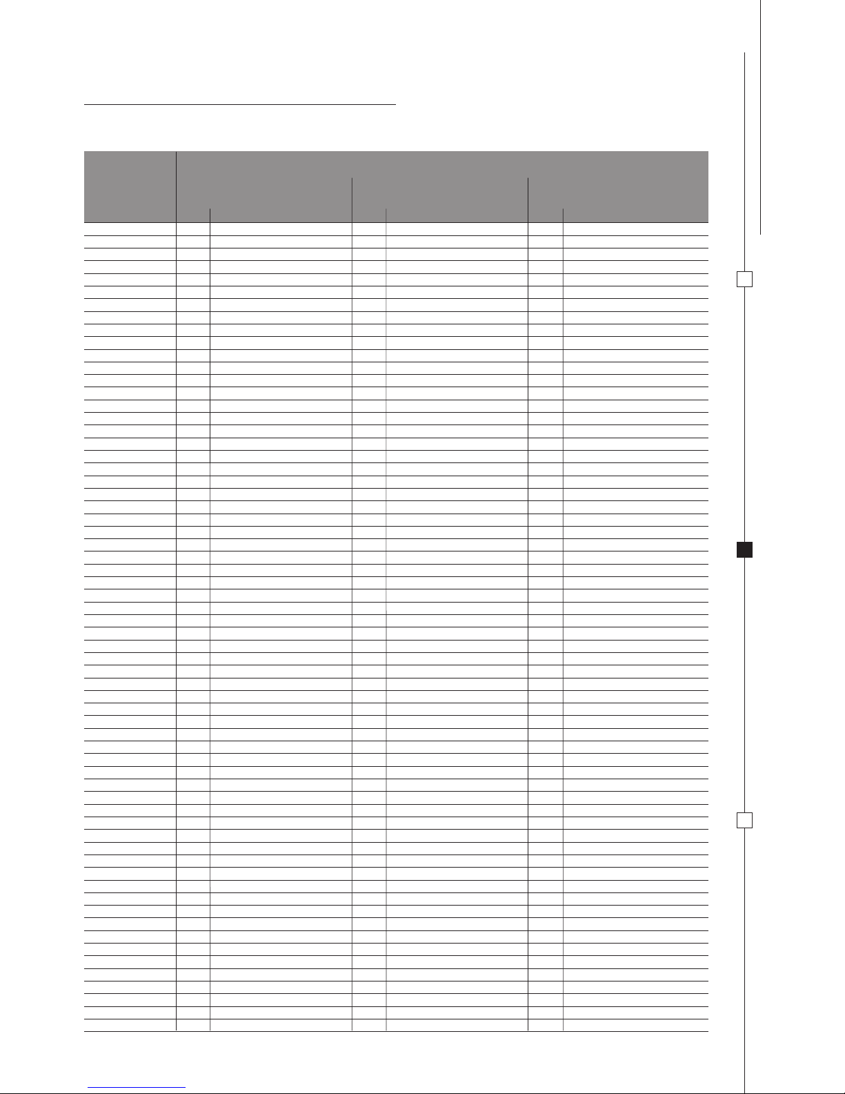
MODEL TOTAL NOMINAL THERMAL
CAPACITY
AIR VOLUME REQUIRED FOR
COMBUSTION
MO8801D - MO8801S - MO8821D
MO8821S - PI8621A
PI8621S
PI8621R
MO8302 - MO8322 - MO8342
MO8362 - MO9202D - MO9202S
MO9222D - MO9222S
PI8002 - PI8022 - PI8042 - PI8062
PI8502 - PI8522 - PI8542 - PI8562
PI8802D - PI8802S - PI8822D - PI8822S
PI8842D - PI8842S - PI8862D - PI8862S
MO9122
7003 - 7023 - 7103 - 7123
8103 VD - 8103 VDM
8123 VD - 8123 VDM
8203 - 8203 M - 8223 - 8223 M
MO8303 - MO8323 - PI9003 - PI9023
PI7203 - PI7223 - PI7703 - PI7723
PI8003 - PI8023 - PI8043 - PI8063
PI8403 - PI8423 - PI8443 - PI8463
PI8503 - PI8523 - PI8543 - PI8563
kW - gr/h m3/h
1,0 - 73
1,8 - 131
2,2 - 160
2,8 - 204
3,2 - 233
3,6 - 262
3,8 - 277
4,6 - 335
2,0
3,6
4,4
5,6
6,4
7,2
7,6
9,2
INSTALL ATIONUS E
MAINTENA NC E
15
ENGLISH
FIXTURE
THIS APPLIANCE MUST BE FITTED AND SECURED TO THE CABINET UTILISING THE FIXTURE SCREWS AS
ILLUSTRATED IN FIG. 3 - PG.131.
The gas supply pipe connected to the appliance must be a rigid metal pipe with sealed fittings. It is possible to fit
a flexible hose, however, in this case the following conditions must be respected:
a) The hose can be accessed easily for inspection;
b) The hose must be protected against coming into contact with parts which heat up (for example parts
underneath the burners);
c) The hose must be protected against being damaged (twisting, pulling, trapping,….);
d) The hose must be protected against being trapped by moving parts (e.g. drawers);
e) The hose must not have a length over 1.5 m;
f) The hose must be replaced before its expiry date;
For models PI8621A, PI8621S, PI8621R seal the appliance gas pipe utilising the sealed tube with pre-mounted
gas fitting provided. Once the appliance has been connected to the gas supply check for gas leaks utilising a noncorrosive fluid. Do not use a water and soap solution. NEVER USE A FLAME TO TEST FOR GAS LEAKS
Models PI8621A, PI8621S and PI8621R are modular. It is possible to connect from 1 to 5 appliances in series.
Disconnect and remove the sealed tube mounted to the gas pipe on the installed appliance and connect it to the
gas pipe on the appliance to install. Connect the appliances together by connecting the gas pipes in series utilising
the fitting.
CONNECTING TO ELECTRICITY SUPPLY
THIS APPLIANCE MUST BE CONNECTED TO A 12 VDC POWER PACK ONLY. THE
CIRCUIT MUST BE FITTED WITH A SAFETY FUSE NOT HIGHER THAN 3 AMP.
WHEN WIRING RESPECT CORRECT POLARITY!
IT IS OF UTMOST IMPORTANCE NEVER TO CONNECT THIS APPLIANCE TO MAINS
VOLTAGE (230 V) WHICH IRREVERSIBLY DAMAGES APPLIANCE COMPONENTS AND
CREATES A HAZARD TO THE USER.
To connect the appliance use a 1.5 mm2 double red and black wire and wire to the terminal junction box located at the
rear of the appliance. The red terminal is the positive pole and the black terminal is the negative pole.
This chapter refers only to models with the wording 12 VDC on the appliance specifications label affixed to the
appliance.
WHEN INSTALLING AND CONNECTING THE APPLIANCE TO THE GAS SUPPLY,
ENSURE THAT THE GAS SUPPLY HOSE IS NOT TWISTED, STRETCHED OR
SUBJECTED TO ANY FORM OF STRAIN WHICH COULD CREATE A HAZARD.
INSTALL ATION
US E
MAINTENA NC E
16
ENGLISH
WARNINGS
THIS APPLIANCE MUST ONLY BE USED BY RESPONSIBLE ADULTS. DURING USE
AND IMMEDIATELY AFTER USE THE BURNER AND OTHER ACCESSIBLE PARTS MAY
BE HOT; DO NOT TOUCH THESE PARTS AND ALWAYS KEEP CHILDREN AT A SAFE
DISTANCE. AFTER USING THE APPLIANCE ENSURE THE KNOB/KNOBS ARE OFF.
AFTER USE ALWAYS SHUT OFF THE GAS SUPPLY AT THE MAIN GAS TAP.
THE USE OF GAS APPLIANCES GENERATES HEAT AND MOISTURE IN THE
IMMEDIATE AREA. ALWAYS ENSURE A GOOD VENTILATION IN THE COOKING
AREA: KEEP ALL AIR VENTS OPEN FOR NATURAL VENTILATION OR INSTALL AN
EXTRACTOR FAN (COOKERHOOD).
DUE TO INTENSIVE USE OF THE APPLIANCE IT MAY BE NECESSARY TO INCREASE
VENTILATION SUCH AS OPENING A WINDOW OR INCREASING COOKERHOOD
(EXTRACTOR FAN) SPEED.
FOR MODELS MO8800 THE DRAINER MUST BE REMOVED WHEN UTILISING THE
HOB BURNER/S.
CAUTION: THIS WARNING IS AFFIXED IN VISIBLE LOCATION ON THE HOB
GLASS LID. GLASS HOB LIDS MAY SHATTER WHEN HEATED. ALWAYS RAISE
THE LID BEFORE IGNITING A BURNER/S (HOB, OVEN AND GRILL) AND TURN OFF
ALL BURNERS (HOB, OVEN AND GRILL) AND LET THEM COOL DOWN BEFORE
LOWERING THE HOB GLASS LID.
CAUTION: THIS WARNING REFERS TO MODELS WITH INCORPORATED SINK
UNIT AND HOB AND WITH GLASS LID DIVIDED BETWEEN SINK AND HOB.
THIS WARNING IS AFFIXED IN A VISIBLE POSITION ON THE SINK UNIT GLASS
LID. WHEN USING THE HOB WITH THE GLASS LID ON THE SINK UNIT CLOSED,
ALWAYS KEEP PANS ON HOB AT A DISTANCE OF 10 MM MINIMUM FROM SINK
UNIT GLASS LID.
The following symbols indicate the burner corresponding to the control knob.
NOTE: different models may have different knobs and different symbols.
THIS SYMBOL IS PLACED NEXT TO THE HOB BURNER KNOBS.
FULL DOT REFERS TO THE CORRESPONDING HOB BURNER.
GAS OFF
HIGH FLAME
LOW FLAME
The following symbols indicate the burner regulation corresponding to the knob position.
NOTE: different models may have different knobs and different symbols.
OTHER SYMBOLS
PUSHBUTTON ELECTRONIC IGNITION
CONTROLS
INSTALL ATIONUS E
MAINTENA NC E
17
ENGLISH
BURNERS
Technical specifications for burners referring to appliance model:
7003 2 1 73 1 1,8 131
7023 2 1 73 1 1,8 131
7103 2 1 73 1 1,8 131
7123 2 1 73 1 1,8 131
8103 VD 2 1 73 1 1,8 131
8103 VDM 2 1 73 1 1,8 131
8123 VD 2 1 73 1 1,8 131
8123 VDM 2 1 73 1 1,8 131
8203 2 1 73 1 1,8 131
8203 M 2 1 73 1 1,8 131
8223 2 1 73 1 1,8 131
8223 M 2 1 73 1 1,8 131
MO8302 1 1 73 1 1,8 131
MO8303 2 1 73 1 1,8 131
MO8322 1 1 73 1 1,8 131
MO8323 2 1 73 1 1,8 131
MO8342 1 1 73 1 1,8 131
MO8362 1 1 73 1 1,8 131
MO8801D 1 1 73
MO8801S 1 1 73
MO8821D 1 1 73
MO8821S 1 1 73
MO9122 2 1,8 131
MO9202D 1 1 73 1 1,8 131
MO9202S 1 1 73 1 1,8 131
MO9222D 1 1 73 1 1,8 131
MO9222S 1 1 73 1 1,8 131
PI7203 1 1 73 2 1,8 131
PI7223 1 1 73 2 1,8 131
PI7703 1 1 73 2 1,8 131
PI7723 1 1 73 2 1,8 131
PI8002 1 1 73 1 1,8 131
PI8003 1 1 73 2 1,8 131
PI8022 1 1 73 1 1,8 131
PI8023 1 1 73 2 1,8 131
PI8042 1 1 73 1 1,8 131
PI8043 1 1 73 2 1,8 131
PI8062 1 1 73 1 1,8 131
PI8063 1 1 73 2 1,8 131
PI8403 1 1 73 2 1,8 131
PI8423 1 1 73 2 1,8 131
PI8443 1 1 73 2 1,8 131
PI8463 1 1 73 2 1,8 131
PI8502 1 1 73 1 1,8 131
PI8503 1 1 73 2 1,8 131
PI8522 1 1 73 1 1,8 131
PI8523 1 1 73 2 1,8 131
PI8542 1 1 73 1 1,8 131
PI8543 1 1 73 2 1,8 131
PI8562 1 1 73 1 1,8 131
PI8563 1 1 73 2 1,8 131
PI8621A 1 1 73
PI8621R 1 2,2 160
PI8621S 1 1,8 131
PI8802D 1 1 73 1 2,2 160
PI8802S 1 1 73 1 2,2 160
PI8822D 1 1 73 1 2,2 160
PI8822S 1 1 73 1 2,2 160
PI8842D 1 1 73 1 2,2 160
PI8842S 1 1 73 1 2,2 160
PI8862D 1 1 73 1 2,2 160
PI8862S 1 1 73 1 2,2 160
PI9003 2 1 73 1 1,8 131
PI9023 2 1 73 1 1,8 131
THERMAL CAPACITY BURNERS MODEL
SEMI-RAPID
Ø 62 mm
AUXILIARY
Ø 47 mm
RAPID
Ø 77 mm
nr. Kw gr/h nr. Kw gr/h nr. Kw gr/h
INSTALL ATION
US E
MAINTENA NC E
AUXILIARY
Ø 47 mm
from 6 to 16 cm
SEMI-RAPID
Ø 62 mm
from 16 to 22 cm
RAPID
Ø 77 mm
from 16 to 22 cm
BURNER PAN DIAMETER
18
ENGLISH
To ignite burner, gently push-in and turn the control knob to position HIGH FLAME and maintaining the knob pushed
at the same time press the electronic ignition pushbutton. Once the burner is alight maintain the knob in this position
for a few seconds to the ensure the flame remains alight.
-MANUAL IGNITION HOB
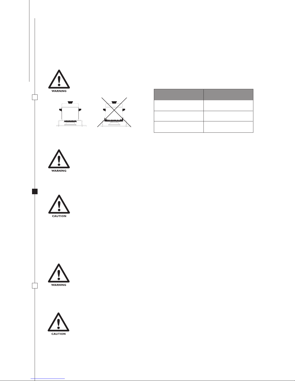
THE FLAME MUST NEVER EXTEND BEYOND THE EDGE OF THE PAN. CENTRE THE
PAN OVER THE BURNER ENSURING STABILITY ON THE PAN SUPPORT.
- SELECTING BURNER
- ELECTRONIC IGNITION HOB (DEPENDING ON MODEL)
HOB
Manual ignition when the appliance is not fitted with the electronic ignition feature or in the event of failure in the
electronic ignition.
MAKE SURE THERE ARE NO PANS OR OTHER ANY OBJECTS ON THE BURNERS
WHEN IGNITING.
IF THE BRUNER DOES NOT IGNITE IMMEDIATELY REPEAT IGNITION AFTER
HAVING FOLLOWED EACH STEP BELOW:
• TURN THE KNOB TO “SMALL FLAME”
• PROCEED WITH MANUAL IGNITION
• CHECK THERE IS SUFFICIENT GAS IN THE GAS BOTTLE.
IF THE APPLIANCE STILL DOES NOT IGNITE SHUT OFF THE GAS SUPPLY AT THE
MAIN GAS TAP AND CONTACT YOUR LOCAL DEALER.
MAKE SURE THERE ARE NO PANS OR OTHER ANY OBJECTS ON THE BURNERS
WHEN IGNITING.
To ignite burner, gently push-in and turn the control knob to position HIGH FLAME and maintaining the knob pushed at
the same time light the burner with a match or gas lighter. Once the burner is alight maintain the knob in this position
for a few seconds to ensure the flame remains alight.
IF THE BURNER DOES NOT IGNITE IMMEDIATELY CHECK THERE IS SUFFICIENT
GAS IN THE GAS BOTTLE.
IF THE APPLIANCE STILL DOES NOT IGNITE SHUT OFF THE GAS SUPPLY AT THE
MAIN GAS TAP AND CONTACT YOUR LOCAL DEALER.
- HOB FLAME REGULATION
To regulate flame turn the knob to the desired cooking flame.

INSTALL ATIONUS E
MAINTENA NC E
19
ENGLISH
GAS CYLINDERS/BOTTLES
The appliance runs off standard gas bottles which can be found in the country of use. The type of gas to use is clearly
marked on the packaging and on the specifications label affixed to the rear of the appliance. However always respect the
following instructions: gas bottles must always be located and positioned in the compartment provided for this purpose.
They must always be vertical and fitted with a valve and pressure regulator. Do not obstruct or impede access to the
gas bottle to permit quick and easy access when replacing.
WARNING! When replacing the gas bottle always take the following precautions:
a) close all gas knobs (Pos. OFF);
b) make sure there are no flames or fires in proximity of the gas bottle;
c) close the gas valve on the bottle to be replaced;
d) unscrew the pressure regulator on the empty bottle and remove the bottle from the purpose compartment. This
procedure is inverted for fitting a new bottle. Check for gas leaks utilising a non-corrosive fluid. Do not use a water
and soap solution.
NEVER USE A FLAME TO CHECK FOR GAS LEAKS;
e) ignite the burners to check they function correctly. If there are problems call in an authorised gas service engineer.
AFTER APPLIANCE USE ALWAYS TURN OFF THE GAS TAP ON THE BOTTLE
GAS LEAKS
We recommend the use of an electronic and homologated gas detector for checking ambient air.
If there is a smell of gas;
a) immediately open the windows and evacuate the vehicle or caravan.
b) do not turn on or off light switches or other electronic appliances, do not light matches or lighters or anything that
could cause the gas to ignite;
c) put out any flames
d) shut off the valve on the gas bottle or cylinder. Do not re-open this valve unless the gas leak has been identified and
eliminated.
e) contact a specialised gas service engineer.
NEVER OPERATE THE APPLIANCE WITH GAS AND OR AT GAS PRESSURES
DIFFERENT TO THOSE INDICATED BY SMEV AS THIS COULD CAUSE IRREGULAR
AND INCORRECT OPERATION. SMEV DECLINES ALL RESPONSIBILITY FOR
DAMAGE OR INJURY CAUSED BY AN INCORRECT OR IMPROPER USE OF THE
APPLIANCE.
VISUAL FLAME CONTROL
Depending on the type of gas used the flame should be:
Propane (G31): blue flame without yellow tips.
Butane (G30): flame with yellow tips when ignited which becomes more intense in colour as the burner heats.

INSTALL ATION
US E
MAINTENA NC E
BURNER
Ø INJECTOR (mm)
SEMI-RAPID
Ø 62 mm
STAMPED N.
AUXILIARY
Ø 47 mm
0,50 50
RAPID
Ø 77 mm
0,75 75
When removing and mounting the injectors the injector holder must be must be held in place with the aid of a tool
(FIG. 5 - PG. 134).
0,67 67
20
ENGLISH
SMEV ACCESSORIES
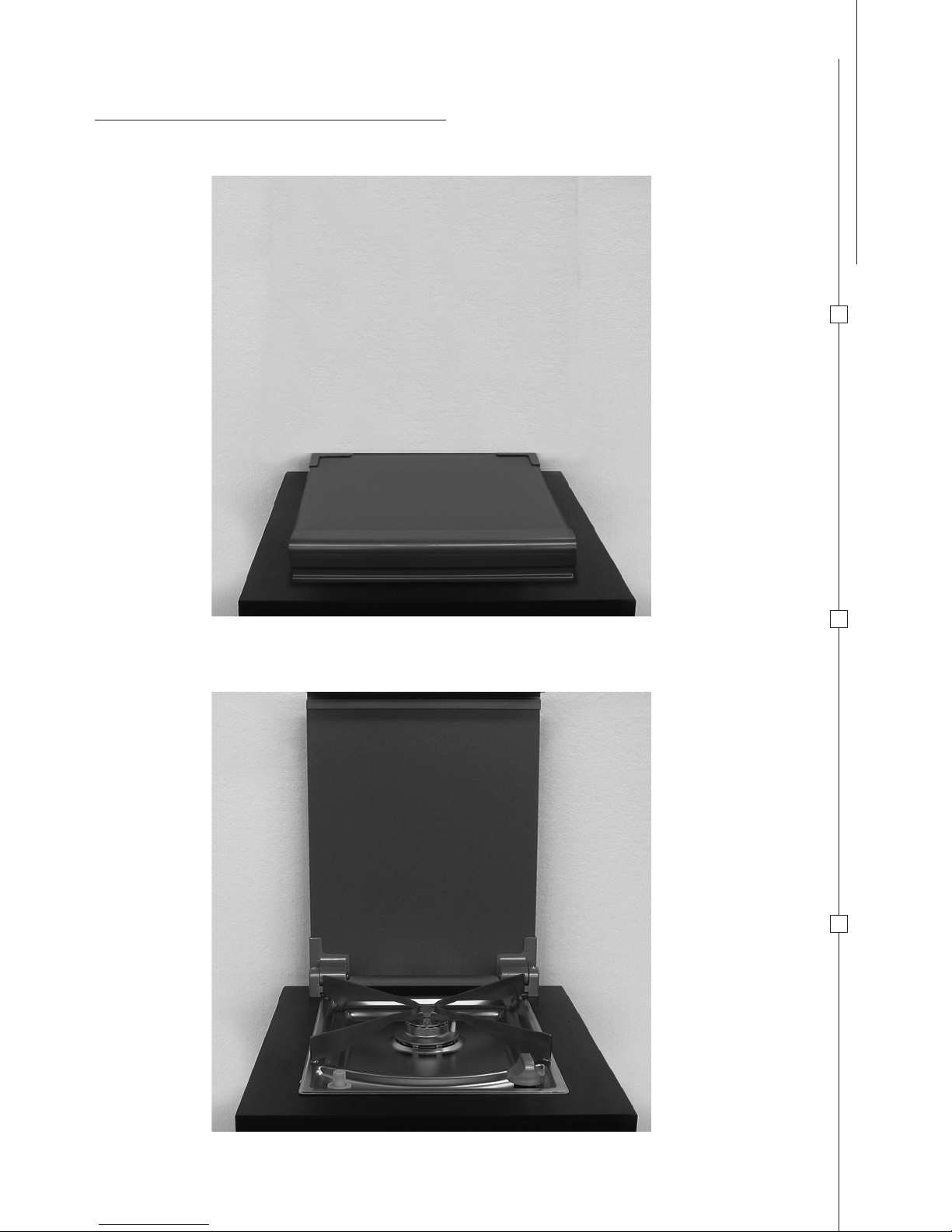
GLASS LID (FIG. 6 - PG. 135) only for models PI8621A, PI8621S, PI8621R.
This optional accessory has two functions: when closed it can be used as an additional work surface and when open,
during cooking, it protects the wall behind the appliance from food splashes.
To request a GLASS LID, please contact your local dealer
TEST PRESSURE POINT (IF FITTED)
THE TEST PRESSURE POINT (PRESSURE CHECK VALVE) IS FITTED UNDER THE HOB. (FIG. 4 - PG. 133).
Removing and mounting this test pressure point (pressure check valve) must be performed by a qualified gas service
engineer. Gas pressure is related to the type of gas used to supply the appliance. Refer to chapter GAS in this manual.
BEFORE CLEANING THE APPLIANCE ALWAYS TURN IT OFF AND DISCONNECT
FROM POWER SUPPLY AND WAIT UNTIL IT HAS COOLED DOWN.
SURFACES THAT ARE STILL HOT CAN BE DAMAGED IF THEY COME INTO
CONTACT WITH COLD WATER OR A DAMP CLOTH.
NEVER USE ABRASIVE, CORROSIVE OR CHLORINE BASED CLEANING PRODUCTS.
NEVER USE STEEL OR PLASTIC SCOURING PADS. NEVER LEAVE DEPOSITS OF
ACID OR ALKALINE SUBSTANCES (VINEGAR, SALT, LEMON JUICE ETC.) ON THE
APPLIANCE. STAINLESS STEEL OR ENAMELLED SURFACES MUST BE CLEANED
ONLY WITH WATER AND SOAP OR A NEUTRAL DETERGENT, THOROUGHLY RINSE
AND DRY. USE CLEAN SPONGES OR CLOTHS TO CLEAN.
INJECTORS
CLEANING OR REPLACING GAS INJECTORS MUST ONLY BE PERFORMED BY
AUTHORISED AND QUALIFIED GAS SERVICE ENGINEERS. THE MANUFACTURER
DECLINES ALL RESPONSIBILITY IN REGARD.
CLEANING

121
SLOV E NSKI
OPOMBE

122
1 F I G .
A
C
D
B
B
A
B
C
D
135
135
500
30
mm

123
2 F I G .
X
Y
275 mm
10 mm
421.7 mm
54.9 mm
448 mm
478 mm
X
Y
478 mm
448 mm
253 mm
421.7 mm
R30 mm
R
30
mm
151.7 mm
178 mm
13
5°
135°
R
30
R3
0
129.8 mm
9
0°
29.8 mm
178 mm
225 mm
R2
53
mm
45 mm
285.7 mm
R167
m
m
33.9 mm
R3
0
178 mm
R3
0
R
30
178 mm
151.7 mm
R203
mm
5 mm
10
10
54.9 mm
208 mm
208 mm
A
A
SEZ. A-A
SEZ. B-B
193,01 mm
213,01
mm
205,97 mm
232,89
mm
Y
X
304,65 mm
212,14 mm
mm 393mm 393
57,91 mm
A
A
R2
2
8
0,
4
8
mm
176,73 mm
B
90°
R
20
8,5 mm
SEZ. A-A
170,35 mm57,69 mm
193,01 mm
R1035
,
5
mm
135°
R
20
90°
60°
R20
B
445,89
mm
170 mm
R57 mm
18,
4
mm
12 mm
R57 mm
155 mm
8,5 mm
10 mm
31,6 mm31,6 mm
18,4
mm
MOD. X mm Y mm
7103
7123
786 445,89
MOD. X mm Y mm
8103 VD
8103 VDM
8123 VD
8123 VDM
956 416

124
222,36 mm
R
173
mm
Y
R
10
R
10
R173
R173
45
°
X
R
10
m
m
339,67 mm
22,5°
2
2,
5
°
314 mm
R1
0
mm
R10 mm
R173 mm
90
°
19 mm
R40
m
m
R
10
R
17
3 mm
217 mm
R10
232,5 mm
191 mm
R1
0
300,25 mm
R10
mm
R1
0
m
m
11 mm
11 mm
11 mm
X
Y
R 173
m
m
A
A
SEZ. A-A
X
Y
R88
R1
95
R182
99,0
5
R7
7
R20
8
R8
8
213
125,05
113,95
201,95
125,36
100
62
212,4
5,28
158,3
133,2
241,26
79,08
R69
3
89,07
106,05
X
Y
A
A
8,5
SEZ. A-A
MOD. X mm Y mm
MO8302
MO8322
MO8303
MO8323
MO8342
MO8362
666 426
MOD. X mm Y mm
PI8802D
PI8822D
PI8842D
PI8862D
MO8801D
MO8821D
511,02 408

125
R69
3
133,2
R182
R19
5
113,95
SEZ. A-A
R8
8
213
8,5
A
A
125,05
5,28
79,08
R77
241,26
158,3
99,0
5
125,36
R20
8
62
212,4
Y
X
100
201,95
R8
8
89,07
106,05
X
Y
MOD. Y mmX mm
511,02 408
PI8802S
PI8822S
PI8842S
PI8862S
MO8801S
MO8821S
X
Y
2
Y
1
18 mm
7,5 mm
SEZ. A-A
B
6 mm
5 mm
R 2,
5
A
B
A
135°
135°
14 mm12,2 mm
13,8 mm
40 mm
X
804 mm
316,7 mm
Y2
Y1
R 3045,3
mm
R
3039,3 mm
12,3 mm
X mm
MO9122
816 316,6 322,7
MOD. Y1 mm Y2 mm

126
MOD. X mm Y mm
MO9202D
MO9222D
883 307
MOD. X mm Y mm
MO9202S
MO9222S
883 307
49 mm49 mm
70 mm
79,3 mm 494,5 mm
150,7 mm 439 mm158,9 mm
211,2 mm
141 mm70 mm
X
Y
1
25
°
R4
5
mm
R100 mm
96 mm
100 mm
45 mm
45 mm
12
5
°
166 mm
2 mm
1
45
°
15 mm
36,4 mm
748,6 mm
793 mm
65,8 mm65,8 mm
67,2 mm67,2 mm
R10
0
94 mm
100 mm
96 mm
94 mm
40 mm
1
45
°
36,4 mm
45 mm
45 mm
R45 mm
166 mm
A
A
7 mm
SEZ. A-A
49 mm 49 mm
70 mm
79,3 mm494,5 mm
150,7 mm mm 9,851mm 934
211,2 mm
141 mm70 mm
X
Y
12
5°
R4
5
m
m
R100 mm
96 mm
100 mm
45 mm
45 mm
12
5
°
166 mm
2 mm
1
45
°
15 mm
36,4 mm
748,6 mm
793 mm
65,8 mm 65,8 mm
mm 2,76mm 2,76
R
10
0
m
m
94 mm
100 mm
96 mm
94 mm
40 mm
14
5
°
36,4 mm
45 mm
45 mm
R
45
mm
166 mm
A
A
7 mm
SEZ. A-A

127
278 mm
139,40 mm
60
°
159,27 mm
25,10 mm
225 mm
173 mm
A
9 mm
SEZ. A-A
R15
m
m
R10 mm
R10 mm
R
10 mm
R2
1
5
m
m
R2
2
2,5
mm
R2
2
9
m
m
R2
2
4 mm
R2
29
m
m
A
X
MOD. X mm Y mm
7003
7023
456,2 466,1
228,1 mm
228,1 mm
238 mm
294,57 mm
13,51 mm
170,07 mm
193,1 mm
13
5°
433,17 mm
278,79 mm
27
8
,79 mm
294,57 mm
X
Y
228,1 mm
193,1 mm
193,1 mm
R35 mm
228,1 mm
228,1 mm
238 mm
294,57 mm
13.51 mm
170.07 mm
193.1 mm
135°~
433,7 mm
278,79 mm
278,79 mm
294,57 mm
456,2 mm
466.1 mm
228,1 mm
193,1 mm
193,1 mm
R3
5
mm
A
A
2 mm
SEZ. A-A
MOD. X mm
PI7203
PI7223
PI7703
PI7723
458

128
248 mm
248 mm
233 mm
179 mm179 mm
233 mm
R7
0
mm
R7
0
mm
135°
135°
Y
X
R3
0
mm
R3
0
mm
R3
0
mm
R3
0
mm
248 mm
248 mm
233 mm
179 mm179 mm
233 mm
301 mm
301
mm
273 mm 273 mm
R70 mm
R70 mm
R7
0
mm
R7
0
mm
135
°
1
35
°
135°
135°
214 mm 214 mm
Y
Y
X
X
R30
m
m
R3
0
mm
R3
0
mm
R3
0
mm
R3
0
mm
R3
0
mm
R30
mm
R3
0
mm
PI8002
PI8022
PI8042
PI8062
PI8502
PI8522
PI8542
PI8562
X mm
466
MOD.
358
Y mm
PI8003
PI8023
PI8043
PI8063
PI8503
PI8523
PI8543
PI8563
X mm
546
MOD.
428
Y mm

129
PI8403
PI8423
PI8443
PI8463
X mm
572
MOD.
332
Y mm
8203
8203 M
8223
8223 M
X mm
506
MOD.
416
Y mm
220 mm
205 mm 76 mm
76 mm
54 mm
92 mm
70 mm
70 mm
8,5
mm
202 mm199 mm
R
55
m
m
R71
mm
R3
1
1 mm
R53
1
m
m
25 mm
130 mm
199 mm
55 mm
216 mm
Y
135°
90°
A
X
X
Y
A
SEZ. A-A
R30
m
m
178 mm
178 mm
Y
151,6 mm
151,6 mm
45 mm
13
5
°
135°
R253
m
m
R30 mm
446 mm
X
R30
mm
393,3 mm
R3
0
mm
SEZ. B-B
B
B

130
X
X
Y
Y
224 mm
46 mm
4 mm
4 mm
R5
mm
54 mm
SEZ.A-A
AA
224 mm
3 mm
3 mm
3 mm
R54 mm
259,47 mm
R136,6 mm
143,5 mm
140 mm
77,54 mm
22,86
°
143,24 mm
119,12 mm
R54 mm
160,14 mm
235 mm
X
Y
109,3 mm
104,13 mm
79 mm
235 mm
278,79 mm
R677 mm
278,79 mm
238 mm
R54 mm
235 mm
294,57 mm
25,98 mm
177,48 mm
R10 mm
R140 mm
R
20
mm
101,6 mm
R
101,6 mm
R140 mm
140 mm
R10
m
m
R20 mm
110,09 mm
A
SEZ. A-A
A
135°
135°
228,1 mm
X
Y
5 mm
PI9003
PI9023
MOD. Y mmX mm
470 473
PI8621A
PI8621S
PI8621R
MOD. Y mmX mm
216 296

131
FIG. 3
MOD:
PI8621A
PI8621R
PI8621S
MOD:
7003
7023
7103
7123
MO8302
MO8303
MO8322
MO8323
MO8342
MO8362
MO8801D
MO8801S
MO8821D
MO8821S
MO9202D
MO9202S
MO9222D
MO9222S
PI7203
PI7223
PI7703
PI7723
PI8403
PI8423
PI8443
PI8463
PI8802D
PI8802S
PI8822D
PI8822S
PI8842D
PI8842S
PI8862D
PI8862S
PI9003
PI9023

132
Y
X
≥ 21 mm
≤ 25 mm
≥ 16 mm
≤ 21 mm
X
MOD:
PI8002
PI8003
PI8022
PI8023
PI8042
PI8043
PI8062
PI8063
PI8502
PI8503
PI8522
PI8523
PI8542
PI8543
PI8562
PI8563
Y
X
X
≥21 mm
≤25 mm
≥16 mm
≤21 mm
MOD:
8103 VD
8103 VDM
8123 VD
8123 VDM
8203
8203 M
8223
8223 M

133
MOD:
MO9122
FIG. 4

134
FIG. 5
135
FIG. 6
 Loading...