

WHOTO
CONTACT
For service of your appliance, firstly
conun
your selling agent.
Australia
DometieAustralia,
Queensland
I
I John Duncan
Court
Varsity
Lakes
QLD
~227
phone;
+61
(0)755076000
fax:
+61
(0)755076001
e-mail:
sales@dometic-waeco.tom.au
web: www.dometic-waeco.com.au
Dometic
Australia.
Queensland
2
21129
South Pine Road
Brendale QLD 4500
phone:
+61
(0)7 3205 7599
fax:
+61
(0)73881
1405
e-mail:
sales@dometic-waeco.com.au
web; www.dometic-waeco.com.au
New
Zealand
Dometic
New
Zealand
Limited,Auckland
Unit
IS,
180
Montgomerie
Road
Airport Oaks,Auckland
1701
phone: +64 (0)9 256 0018
fax:
+64(0)92560017
e-mail: sales2@dometic.co.nz
web: www.dometic.co.nz
L
Dometic
Australia.
Victoria
Bldg
3B.
Claycon Business Park
1508
Centre
Rd,
Clayton
VIC
3168
phone:
+61
(0}39239
1000
fax:
+61
(0)39239
1099
e-mail: sales@dometic-waeco.com.au
web: www.dometic-waeco.com.au
Dometic
Australia,
Western
Australia
12
Prosperity
AV{!,
WangaraWA6065
phone:
+61
(0)89209 3033
fax:
+61
(0)892093577
e-mail: sales@dometic-waeco.com.au
web: www.dometlc·waeco.com.au
Dometie
New
Zealand
Limited,Welllngton
26 Cashew Street
Grenada North,Wellington
6+40
phone; +64 (0)4 232 3898
fax:
+64 (0)4 232 3878
e-mail: customerservices@dometlc.co.nz
web: www.dometic.co.nz
I
S,\\I~'~
by
Dometic
GROUP
Gas Safety
Certified
Built-in
Hotplate,
Ovens,
Stoves,
Minigrills,
Hotplate-Sink
Combos
for
Recreational
Vehicles
and
Marine.
Models:
CU311 - CU311 M • CU333 - CU333M - CU335 •
CU335M·
CU401 -
CU40IPE·
CU402·
CU402PE
-
CU403 • CU403PE • F031 I -
M08103-
M08123
•
P18002
- PI8022 -
P18003•PI8023
•VN555
Installation,
use
and
service
manual
CONTENTS
S!\\I~"
by
Dometic
GROUP
N!"I~"
by
Dometic
GROUP
I.
GENERAL INFORMATION
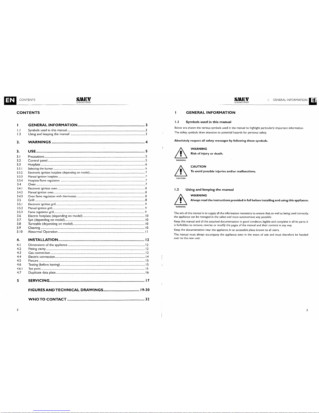
CONTENTS
GENERAL
INFORMATION
1
1.1
1.2
GENERAL
INFORMATION
3
Symbols
usedinthis
manual
3
Using
and
keeping
the
manual
3
1.1
Symbols
usedinthis
manual
Below are shown
the
various symbols usedinthe
manualtohighlight particularly important information.
The
safety symbols draw attentiontopotential hazards for personal safety.
2.
WARNINGS
i 4
Absolutely
respect
all
safety
messages
by following
these
symbols.
CAUTION
WARNING
WARNING
CAUTION
WARNING
Riskofinjuryordeath.
To avoid
possible
injuries
and/or
malfunctions.
The
aimofthis manualisto
supply
all
the
information necessarytoensure that, as well as being used correctly,
the
appliance can be managedinthe
safest and
most
autonomous
way possible.
Keep this manual and
all
the
attached documentationingood
condition, legible and completeinall
its parts; it
is
forbiddentoremove, rewriteormodify
the
pages of
the
manual and
their
contentinany
way.
Keep
the
documentation near
the
appliance,inan accessible place knowntoall
users.
The
manual must always accompany
the
appliance eveninthe
eventofsale and must
therefore
be handed
over
to
the
new user.
1.2
Using
and
keeping
the
manual
6
WARNING
,
Always
read
the
instructions
provided
in full
before
installing
and
using
this
appliance.
. .
INSTALLATION
12
Dimensionsofthe
appliance
12
Fitting cavity , 12
Gas
connection
12
Electric
connection
14
Fixture
15
Testing
(before
leaving)
15
Test point
15
Duplicate
data
plate
16
USE 5
Precautions
5
Control
panel
5
Hotplate
6
Selecting
the
burner
6
Electronic ignition hotplate (depending on model) 7
Manual ignition hotplate 7
Hotplate flame regulation 7
Oven
7
Electronic ignition oven 8
Manual
ignition oven 8
Oven flame regulation with
thermostat
8
Grill 8
Electronic ignition grill 9
Manual
ignition grill 9
Flame regulation grill 9
Electric
hotplate
(dependingonmodel)
:
10
Spit
(dependingonmodel)
10
Turntable
(dependingonmodel)
10
Cleaning
10
Abnormal
Operation
, I I
4.
4.\
4.2
4.3
4.4
4.5
4.6
4.6.1
4.7
3.
3.1
3.2
3.3
3.3.1
3.3.2
3.3.3
3.3.4
3.4
3.4.1
3.4.2
3.4.3
3.5
3.5.1
3.5.2
3.5.3
3.6
3.7
3.8
3.9
3.10
5
SERViCiNG
17
FIGURESANDTECHNICAL
DRAWINGS
19-30
WHOTO
CONTACT
32
2
3
2.
WARNINGS
S,\\I~"
by
Dometic
GROUP
2.
WARNINGS
3.
USE
Do
not
useorstore
flammable materialsinthe
appliance
storage
drawerornear
this appliance.
3.1
Precautions
Do
not
spray aerosolsinthe
vicinityofthis appliance while itisin
operation.
Do
not
modify this appliance.
Where
this applianceisinstalledinmarine craftorin
caravans, it shall
NOT
be used as a space heater.
This appliance shall be installed onlybyauthorised
persons andinaccordance with
the
manufacturer's
installation instructions,local gas fitting regulations, municipal building codes, electrical wiring regulations,AS
5601-2004 -
Gas
Installations
and any
other
statutory
regulations.
This appliance must be used onlyina well ventilated environment.Donot
obstruct
the
flowofcombustion
and ventilation
air.
This applianceisdesigned and manufactured for cooking food only.Any
other
useisconsidered improper and
incorrect creating hazardous conditions.The manufacturer declines
all
responsibility for damagetothings
or
injuriestopersons caused by
incorrect
installation and /orincorrect
and
improper
use.
If
the
applianceisto
be left unused for any lengthoftime, itisrecommended
that
the
gas supply be turned off
at
the
cylinderormain supply valve feeding
the
appliance.
CAUTION
WARNING
WARNING
WARNING
CAUTION
CAUTION
This
appliance
must
onlybeusedbyresponsible
adults.
During
use
and
immediately
after
use
the
burner
and
other
accessible
parts
maybehot;donot
touch
these
parts
and
always
keep
childrenata
safe
distance.
After
using
the
appliance
ensure
the
knob/knobs
are
off.
After
use
always
shut
off
the
gas
supplyatthe
main
gas
tap.
WARNING
This
appliance
must
notbeusedbypersons
(including
children)
who
suffer
from
psychical
and
motor
related
disordersorwho
are
not
familiar
withorwho
have.'lo
experience
with
the
appliance
unless
under
supervisionorare
being
instructed
on
howtouse
the
appliancebythe
person
responsible
for
their
safety.
Children
must
alwaysbesupervisedtoprevent
them
from
playing
with
the
appliance.
WARNING
The
useofgas
appliances
generates
heat
and
moistureinthe
immediate
area.
Always
ensureagood
ventilationinthe
cooking
area:
keep
all
air
vents
open
for
natural
ventilationorinstallanextractor
fan
(cookerhood).
WARNING
An
intense
and
prolonged
use
ofthe
appliance
may
require
additional
ventilation,
for
example
openingawindow,orincreasing
the
powerofany
mechanical
extraction
system.
CAUTION
Before
cooking
with
the
oven
and
grill
for
the
first
time
turnonthe
ovenorgrill
at
high
flame
and
leave
the
ovenonforatleast30minutes
and
the
grill
for
15·20
minutes.
Before
opening
the
glass
coverofthe
hotplate,
remove
any
liquids
that
may
have
spilled.
WARNING
This
warning
is affixed in a visible
locationonthe
hotplate
glass
lid.
Glass
hotplate
lids
may
shatter
when
heated.
Always
raise
the
lid
before
ignitingaburner/s
(hotplate,
oven
and
grill)
and
turn
off
all
burners
(hotplate,
oven
and
grill)
and
let
them
cool
down
before
lowering
the
hotplate
glass
lid.
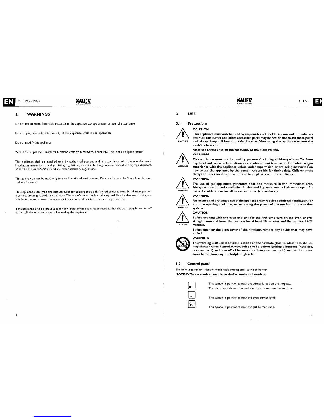
3.2
Control
panel
The
following symbols identify which knob
correspondstowhich burner.
NOTE:
Different
models
could
have
similar
knobs
and
symbols.
This symbolispositioned
near
the
burner
knobs on
the
hotplate.
The
black
dot
indicates
the
positionofthe
burneronthe
hotplate.
This symbolispositioned near
the
oven
burner
knob.
This symbolispositioned
near
the
grill
burner
knob.
4
5
ma
3.
USE
S,\\I~"
by
Dometic
GROUP
_________
~_:~_!_~_i~_?R_!_:
3._U_S_E_____.JU
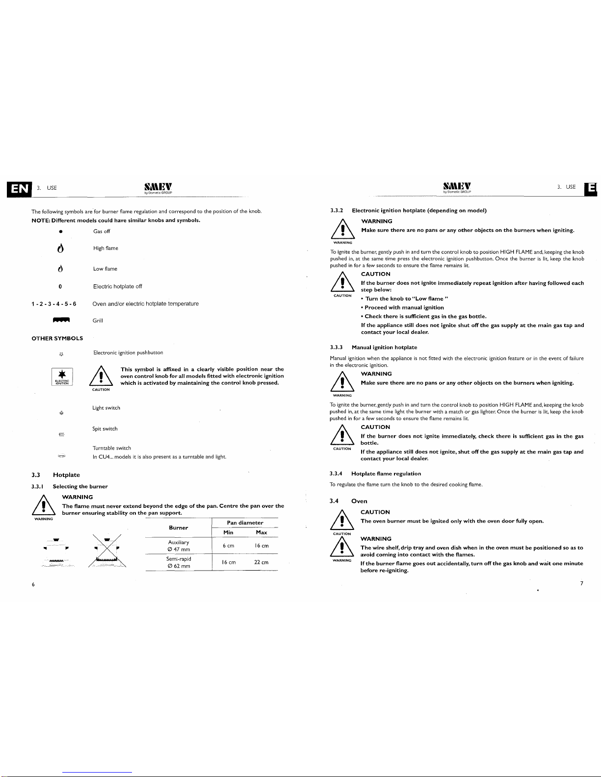
The following symbols are-for burner flame regulation and correspondtothe
position of the knob.
NOTE:
Different
models
could
have
similar
knobs
and
symbols.
•
Gas off
3.3.2
Electronic
ignition
hotplate
(dependingonmodel)
WARNING
Make
sure
there
arenopansorany
other
objectsonthe
burners
when
igniting.
WARNING
To
ignite the burner. gently pushinand turn
the
control knobtoposition
HIGH
FLAME
and. keeping the knob
pushed
in.
at the same time press
the
electronic ignition pushbutton.
Once
the
burnerislit.
keep the knob
pushed
in
for a
few
secondstoensure the flame remains
lit.
o
1-2-3-4-5-6
OTHER
SYMBOLS
High
flame
low
flame
Electric hotplate off
Oven and/or electric hotplate temperature
Grill
CAUTION
CAUTION
If
the
burner
does
not
ignite
immediately
repeat
ignition
after
having
followed
each
step
below:
•
Turn
the
knobto"Low
flame"
•
Proceed
with
manual
ignition
•
Check
thereissufficient
gasinthe
gas
bottle.
If
the
appliance
still
does
not
ignite
shut
off
the
gas
supplyatthe
main
gas
tap
and
contact
your
local
dealer.
CAUTION
Electronic ignition pushbutton
Make
sure
there
arenopansorany
other
objectsonthe
burners
when
igniting.
WARNING
3.3.3
Manual
ignition
hotplate
Manual
ignition when the applianceisnot
fitted with
the
electronic ignition featureorin
the event of failure
in
the
electronic ignition.
This
symbol
is affixed in a
clearly
visible
position
near
the
oven
control
knob
for
all
models
fitted
with
electronic
ignition
whichisactivatedbymaintaining
the
control
knob
pressed.
WARNING
Light
switch
To
ignite
the
burner. gently pushinand turn the control knobtoposition HIGH
FLAME
and. keeping the knob
pushed
in.atthe same time light the burner with a matchorgas lighter.
Once
the burnerislit.
keep
the
knob
pushed
in
for a
few
secondstoensure the flame remains
lit.
E
Spit switch
Turntable switch
In
CU4
...
modelsitis
also presentasa turntable and
light.
CAUTION
CAUTION
If
the
burner
does
not
ignite
immediately,
check
thereissufficient
gasinthe
gas
bottle.
If
the
appliance
still
does
not
ignite,
shut
off
the
gas
supplyatthe
main
gas
tap
and
contact
your
local
dealer.
3.3
Hotplate
3.3.4
Hotplate
flame
regulation
3.3.1
Selecting
the
burner
To
regulate
the
flame turn the knobtothe
desired cooking flame.
WARNING
..
WARNING
The
wire
shelf,
drip
tray
and
oven
dish
wheninthe
oven
mustbepositionedsoas
to
avoid
coming
into
contact
with
the
flames.
If
the
burner
flame
goes
out
accidentally,
turn
off
the
gas
knob
and
wait
one
minute
before
re-igniting.
CAUTION
The
oven
burner
mustbeignited
only
with
the
oven
door
fully
open.
WARNING
3.4
Oven
&
CAUTION
&
Pan
diameter
Burner
Min
Max
Auxiiiary
6cm
16
cm
047
mm
Semi-rapid
16
cm 22
cm
062
mm
JIl'
WARNING
The
flame
must
never
extend
beyond
the
edgeofthe
pan.
Centre
the
pan
over
the
burner
ensuring
stabilityonthe
pan
support.
----------,.-----------
_
..
-
6
7
IaDL-
3
_.
~U_S_E~~~~~~~~~~~~~_D~~_~\_'ti_~?_R~_~~_·
~~~~~~~~_
_
~_y:_~~_~_i~_!_!_~
~~~~~
__
3_._U_SE_g
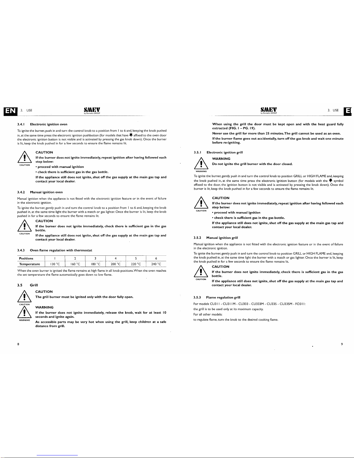
3.4.1
Electronic
ignition
oven
To
ignite the burner, pushinand turn
the
control knobtoa position from Ito6 and, keeping the knob pushed
in,
at the same time press
the
electronic ignition pushbutton (for models
that
have
*affixed
to
the
oven
door
the electronic ignition buttonisnot
visible andisactivatedbypressing
the
gas
knob down).
Once
the burner
is
lit,
keep the knob pushedinfor a
few
secondstoensure
the
flame remains
lit.
When
using
the
grill
the
door
mustbekept
open
and
with
the
heat
guard
fully
extracted
(FIG.
I -
PG.
19).
Never
use
the
grill
for
more
than25minutes.
The
grill
cannotbeusedasan
oven.
If
the
burner
flame
goes
out
accidentally,
turn
off
the
gas
knob
and
wait
one
minute
before
re.igniting.
3.4.2
Manual
ignition
oven
Manual
ignition when
the
applianceisnot fitted with the electronic ignition featureorin
the
event of failure
in
the
electronic ignition.
To
ignite
the
burner, gently pushinand turn
the
control knobtoa position from I
to
6 and, keeping the knob
pushed
in,atthe
same time light
the
burner with a matchorgas
lighter.
Once
the
burnerislit,
keep
the
knob
pushed
in
for a
few
secondstoensure the flame remains
lit.
WARNING
WARNING
Do
not
ignite
the
grill
burner
with
the
door
closed.
CAUTION
If
the
burner
does
not
ignite
immediately,
repeat
ignition
after
having
followed
each
step
below:
•
proceed
with
manual
ignition
•
check
thereissufficient
gasinthe
gas
bottle.
If
the
appliance
still
does
not
ignite,
shut
off
the
gas
supplyatthe
main
gas
tap
and
contact
your
local
dealer.
Manual
ignition
grill
CAUTION
3.5.1
Electronic
ignition
grill
To
ignite the burner, gently pushinand turn
the
control knobtoposition
GRILLorHIGH
FLAME
and, keeping
the
knob pushed
in,atthe
same time press
the
electronic ignition button (for models with
the
*symbol
affixed
to
the door,
the
ignition buttonisnot
visible andisactivatedbypressing
the
knob down).
Once
the
burnerislit,
keep
the
knob pushedinfor a
few
secondstoensure the flame remains
lit.
3.5.2
CAUTION
If
the
burner
does
not
ignite
immediately,
repeat
ignition
after
having
followed
each
step
below:
•
proceed
with
manual
ignition
•
check
thereissufficient
gasinthe
gas
bottle.
If
the
appliance
still
does
not
ignite,
shut
off
the
gas
supplyatthe
main
gas
tap
and
contact
your
local
dealer.
CAUTION
If
the
burner
does
not
ignite
immediately,
check
thereissufficient
gasinthe
gas
bottle.
If
the
appliance
still
does
not
ignite,
shut
off
the
gas
supplyatthe
main
gas
tap
and
contact
your
local
dealer.
CAUTION
CAUTION
When
the
oven burnerisignited the flame remains at
high
flameinall
knob positions.When the oven reaches
the
set
temperature the flame automatically goes downtolow flame.
Temperature
CAUTION
If
the
burner
does
not
ignite
immediately,
check
thereissufficient
gasinthe
gas
bottle.
If
the
appliance
still
does
not
ignite,
shut
off
the
gas
supplyatthe
main
gas
tap
and
contact
your
local
dealer.
CAUTION
Manual
ignition when
the
applianceisnot
fitted with
the
electronic ignition featureorin
the event of failure
in
the
electronic ignition.
To
ignite the burner, gently pushinand turn
the
control knobtoposition
GRILLorHIGH
FLAME
and, keeping
the knob pushed
in,atthe same time light
the
burner with a matchorgas
lighter.
Once
the
burnerislit,
keep
the knob pushed
in
for a
few
secondstoensure the flame remains
lit.
3.5.3
Flame
regulation
grill
For models
CU31
I - CU311 M - CU333 - CU333M - CU33S - CU33SM - F0311:
the
grillisto
be used onlyatits maximum capacity.
For
all
other
models:
to
regulate flame, turn
the
knobtothe
desired cooking flame.
6
240°C
WARNING
If
the
burner
does
not
ignite
immediately,
release
the
knob,
wait
foratleast
10
seconds
and
ignite
again.
As
accessible
parts
maybevery
hot
when
using
the
grill,
keep
childrenata
safe
distance
from
grill.
CAUTION
The
grill
burner
mustbeignited
only
with
the
door
fully
open.
Grill
Oven
flame
regulation
with
thermostat
Positions
WARNING
3.4.3
3.5
it
CAUTION
it
8 9

lm,--_3_.
_u_sE
~_~_~~_~_ti~_!_!_~
.
__________
~_:~_~\_et;_~G_~R_!'_p
3_._U_S_E-----.J~
Never
use
steam
cleanerstoclean
the
appliance.
CAUTION
Hot
surfaces
maybedamagedoncontact
with
cold
waterorwithawet
cloth.Donot
use
abrasive,
corrosiveorchlorine-based
products,
pot
scourersorsteel
wool.
Do
not
leave
acidoralkaline
substances
(vinegar,
salt,lemon
juice,
etc.)onthe
surfaces
of
the
appliance.
Stainless
steel
surfaces
and
enamelled
parts
mustbewashed
with
water
and
neutral
soapordetergent,
rinsed
and
dried.
Use
clean
sponges
and
cloths.
WARNING
Never
use
abrasive
andIor
coarse
cleaning
materialsormetal
brushestoclean
the
glass
oven
doorasthese
materials
scratch
the
glass
surface
with
the
risk
of
shattering
the
glass.
WARNING
CAUTION
WARNING
Electric
hotplate
(dependingonmodel)
CAUTION
CAUTION
Beforeturningonthe
electric
hotplate
(orifthe
hotplate
has
remained
unused
for
a
long
time)itis
necessarytoeliminate
any
moisturebyturningonthe
hotplate
and
leavingiton
for30minutes
with
the
corresponding
knobinposition
I.
Use
pans
with
flat
bottoms
and
with
diametersnoless
than
the
diameterofthe
hotplate.
Dry
the
bottomofthe
pan
before
placingiton
topofthe
hotplate.
When
using
the
hotplatedonot
leave
the
appliance
unattended
and
make
sure
children
are
nowhere
near
the
appliance.
The electric hotplateiscontrolledbya 7-position knob: position offis0 (zero) whereas positions Ito6 are
for regulating
the
hotplate. Positions Ito6
correspondtoan
increaseintemperatureofthe
hotplate.
There
is
a red LED positioned nexttothe
knob which lightsupwhen
the
hotplateison.
3.6
3.7
Spit
(dependingonmodel)
WARNING
Ignite
the
oven as describedinthe
chapter
3.4 Oven.Turn
the
gas knobtothe
required position. Insert
the
drip tray with
the
spit already installedasillustratedinFIG.2 -
PG.
19.
Press
the
spit buttontoturnonthe
spit motor.
CAUTION
CAUTION
Do
not
leave
heavy
spillovertobake
on,asthis
will
make
cleaning
more
difficult.
3.8
Turntable
(dependingonmodel)
Ignite
the
oven
burner
as indicatedinchapter, 3.4 Oven. Insert
the
turntable as indicatedinFIG.
3 - PG.
19
Press
the
switchtooperate
the
turntable motor.
CAUTION
CAUTION
The
trivet
(pan
support)
canberemovedbycarefully
pulling
the
extended
pins
evenly
outofthe
plastic
locatersinthe
hotplate.
When
replacing
the
trivet,
ensure
that
the
plastic
guides
are
not
damaged.
3.9
Cleaning
No
regular maintenanceisrequired
except
cleaning.
3.10
Abnormal
Operation
WARNING
WARNING
Some
cooking
operations
generateaconsiderable
amountofgrease.This,
combined
with
spillage,
can
becameahazardifallowedtoaccumulateonthe
appliance
through
lackofcleaning.
Gas valves, which are difficulttoturn
are consideredtobe abnormal operation and
may
require servicing.
In
case
the
appliance
failstooperate
correctly,
contact
the
authorised service providerinyour
area.
CAUTION
CAUTION
Keep
the
appliance
clean
andingood
working
condition.To
clean
below
the
hotplate
burners,
remove
the
burner
cap
screws
usingasuitable
screwdriver.
Once
the
screws
are
removed,
the
burner
cap
and
burner
head
canberemovedtoprovide
access
below
the
burner.
Once
cleaned,
ensure
the
burner
head
and
burner
cap
are
refitted.Itis
recommendedtohaveitserviced
annuallybyauthorized
personnel.
WARNING
Before
cleaning
the
appliance
always
turnitoff
and
disconnect
from
power
supply
and
wait
untilithas
cooled
down.
WARNING
10
II

4. INSTALLATION
S.\\I~"
by Dometic
GROUP
S."I~"
by
Dometic
GROUP
4. INSTALLATION
~
TOTAL
NOMINAL
GAS
CONSUMPTION
MJ/h
2,5kg/h
OUTPUT
OFTHE
REGULATOR
Grill
Oven
NQ
MJ/h
NQ
MJ/h
2,75 kPa
AUXILIARY
047mm
NQ
MJ/h
PRESSURE
NOMINAL
GAS
CONSUMPTION
SEMI-RAPID
062mm
NQ
MJ/h
WARNING
The
applianceisnot
suitable
for
connection
withahose
assembly.
WARNING
A
manual
shut-off
valve
shallbeprovidedonthe
inlet
connectionofthe
appliance.
The
valve
shallbeaccessible
for
operation
and
firmly
fixed.
GAS
Model
UNIVERSAL
LPG
WARNING
WARNING
CU311 2
5.9
2
3.8 I
5.2
I 3.8 24.6
CU311M 2
5.9
2
3.8 I
5.2
1 3.8 24.6
CU333 I 5.9 1
3.8
I 5.2 I 3.8 14.9
CU333M I
5.9 1 3.8 I 5.2 I 3.8 14.9
CU335 2 5.9 I
3.8 I 5.2 I 3.8 20.8
CU335M 2 5.9 I
3.8
I 5.2
I
3.8 20.8
CU401
3 5.9 I 3.8 I 5.2 1 3.8 30.5
CU40lPE
2
5.9
I
3.8 I 5.2 I 3.8 24.6
CU402
3 5.9
I
3.8 I
5.2 26.7
CU402PE 2 5.9 I
3.8
I 5.2 20.8
CU403
3 5.9 I 3.8 21.5
CU403PE 2 5.9 I
3.8 15.6
F0311
I 5.2 I 3.8 5.2
M08103
I 5.9 2
3.8
13.5
M08123
I 5.9 2
3.8 13.5
PI8002 I 5.9 1
3.8
9.7
PI8022 I 5.9 I 3.8 9.7
PI8003 2 5.9 I
3.8
15.6
PI8023 2 5.9 I 3.8 15.6
VN555 I 5.2 5.2
Below
are
the
gas characteristics for which
the
applianceisset
(given also on
the
appliance data plate). A
pressure
reducer
suitable for
the
typeofgas used mustbeconnected
between
the
gas cylinder and
the
appliance:
Between
the
top
partofthe
burners
and cabinets and 1orshelves fitted above
the
hotplate.
From
the
sidesofthe
appliance and vertical walls.
From
the
top
sidetothe
cabinets and 1orshelves fitted above
the
appliance.
From
the
external edgeofthe
burner
head
nearesttoa side and 1orback wall.
INSTALLATION
WARNING
WARNING
The
appliance
must
fittedatan
appropriate
and
safe
distance
from
flammable
materials.
This
applianceisnot
connectedtoa flue
terminal
which
discharges
the
product
of
combustiontothe
outside.
Any
enclosed
spaceinwhich
the
applianceisinstalled
must
thereforebeprovided
with
permanent
ventilationinaccordance
with
relevant
federal
and
state
regulationsinforce,
and
the
requirementsofgas
installations
with
particular
attention
being
paidtothe
matterofroom
ventilation.
WARNING
This
appliance
shallbeinstalled
onlybyauthorised
persons
andinaccordance
with
the
manufacturer's
installation
instructions,
local
gas
fitting
regulations,
municipal
building
codes,
electrical
wiring
regulations,AS
5601·2004
- Gas Installations
and
any
other
statutory
regulations.
WARNING
Dimensionsofthe
appliance
170mm
100mm
WARNING
600 mm
200 mm
WARNING
WARNING
Dimensionsoffitting
cavity
Cut
out
a holeinthe
cabinet as illustratedinFIG.
5 - PG.21size
will
dependonappliance model.
The
cabinet must be appropriately
constructed
and aligned horizontally with
the
worktop
and with
the
unit.
The
cabinet
aperture
must be perfectly squared and aligned.Ifthere
are
apertures
for cabinet ventilation,
prevent flammable materials from entering
these.
4.3
Gas
connection
4.2
Fitting
cavity
Minimum allowable distances from walls (FIG.4 - PG. 20)
For
theCU...,FO...
and
VN555
models,
the
cavity
that
the
applianceisbuilt
into
mustbecompletely
sealed
off.Itis
important
that
the
inside
panelsofthe
cavity
are
WARNING
completely
sealed
anddonot
communicate
with
adjoining
cavitiesorthe
outside.
The
openingsinthe
cavity
that
allow
accesstothe
gas
and
electric
connections
shouldbesealed
with
rubberorfoam.
The
gas connection
(114
BSPT
female)islocatedatthe
rear for models CU
...
, FO
...
and for model VN555,
whereasitisonthe
bottom
for models
Pl...and MO
...
The
electric connectionislocatedatthe
rear
for models CU
...
, FO
...
and for model VN555,
whereasitis
on
the
bottom
for models
PI...
and MO
...
(consult
chapter
4.4 Electric connectiontosee
whether
the
appliance
needs this connection).
The
overall dimensions
are
illustratedinFIG.5 PG.21with
the
cavity diagrams.
The
overall dimensions include
the
trivet (pan support), control knobs, handles and gas connection.
4.
4.1
12
13

4.
INSTALLATION
Si\\n\'
by
Dometic
GROUP
Ni\\U\'
by
Dometic
GROUP
4.
INSTALLATION
U
BURNER
INJECTOR
ORIFICE
(mm)
STAMPED
N!l
AUXILIARY(047mm)
0.57
57
SEMI-RAPID(062mm)
0.72 72
OVEN
0.57
57
GRILL
0.67 67
The connection of the
gas
pipetothe appliance (1/4
BSPT
female) must be made with a
rigid
metal pipe.The
pipe
work
and fittings
shall
be free from defects and ofanapproved type.
Once
installed.
the
installation must be checked for leaksbymeans ofanapproved testing method.
Do
not
use a solution of soap and water.
WARNING
Never
useanaked
flametocheck
for
gas
leaks.
The
supply
cord
mustbepositionedinsuchaway
thatitnever
reachesatemperature
of
75°C
above
ambientinany
point.
The
plug
mustbeeasytoaccess
after
installation.
Always
disconnect
electrical
power
before
workingonor
servicing
the)
appliance.
For connectingtothe mains power supply use a socket.
If
the supply cord (H05RR-F 3x0,75mm
2
)
is
damaged. it must be replacedbythe manufacturerorits service
agentora similarly qualified personinordertoavoid a hazard.
4.5
Fixture
CAUTION
This
applianceistobefixed
and
securedtothe
cabinetasdescribed
in FIG. 6 -
PG.
25.
CAUTION
WARNING
4.6
Testing
(before
leaving)
4.4
Electric
connection
Low
voltage
I2 V "-='"
This chapter concerns only models marked12V "-='" on
the
appliance data plate.
CAUTION
Ignite
all
burners both individually and concurrentlytoensure
correct
operation of
gas
valves. burners and
ignition.Turn gas taps
to
low flame position and observe stability of the flame for each burner individually and
concurrently. Ensure
correct
operation of the flame failure protection.
Depending on
the
type of
gas
used.
the
appearance of
the
flameisas
follows:
Propane:
flame with blue centre and well-defined contour.
Butane:
flame with light yellow tips when igniting
the
burner. gradually intensifyingasthe
burner heats.
In
case
the
appliance
failstooperate
correctly
after
all
checks
have
been
carried
out,
shut
off
the
gas
supplyatthe
main
gas
tap
and
refertothe
authorized
service
CAUTION
providerinyour
area.
When satisfied with
the
appliance. please instruct the user on
the
correct
method of operation.
WARNING
Absolutelydonot
connect
the
appliancetothe
mains
voltage
(230
V-),
this
would
destroy
the
components
and
causeahazard
for
the
user.
CAUTION
This
appliance
mustbeconnectedtoa
12V
"-='"
source.The
circuit
mustbeprotected
by a
fuseofno
more
than3Ampere.
Ensure
that
the
polarityofthe
connectioniscorrect!
CAUTION
WARNING
To
connect the appliance use a
1.5
mm2double red and black wire and wiretothe terminal junction box
located at
the
rear of the appliance with the wording "+12V"-="'- ".The red terminalisthe
positive pole and
the black terminalisthe
negative pole.
High
voltage
230-240
V-
This chapter refers onlytothe models listedinthe table below.
Model
CU40 IPE- CU402PE - CU403PE
Nominal
voltage
230-240V-
Nominal
power
800W
4.6.1
Test
point
For
models
PI...MO...CU...
The
test
pointissupplied loose with the appliance (see pictureinFIG.7PG.
29). Remove one burner head. the
injector and screw
in
test
point fitting. The pressureismeasured with the relevant burner
gas
valveonhigh
flame and withaninlet pressure of 2.75
kPa.
For
modelsFO...
The
test
pointisfitted on the
main
gas
pipe. Remove
the
front plastic plaque (see pictureinFIG.8
PG.
29) and
remove the screw. The pressureismeasured withaninlet pressure of 2.75
kPa.
In
these models thereisan
electric plateinthe hotplate.
WARNING
WARNING
.
When
connecting
directtothe
mains
supply,itis
necessarytoinstallacircuit
breaker
which
allows
for
disconnecting
and
isolating
the
appliance
from
the
mains
in
the
eventofovervoltage
III
conformingtoinstallation
regulations.
For
modelsVN555
The
test
pointisfitted on
the
main
gas
pipe. Remove the screw. The pressureismeasured withaninlet
pressure of 2.75
kPa
.
14
15

4. INSTALLATION
S,\\U\'
by
Dometic
GROUP
N,"I~"
by
Dometic
GROUP
5.
SERVICING
iii
4.7
Duplicate
data
plate
5
SERVICING
After installation,
the
data plate may be consultedbyopening
the
doorofthe
ovenorof
the
grill
compartments,
oronthe
backofthe
instructions manual.
The
dateofmanufacture can be deduced from
the
serial number:
the
2nd and
the
3rd figure indicate
the
year,
the
4th and
the
5th figure
the
week. See
the
example below.
O~~993
year
week
&
WARNING
&
WARNING
&
WARNING
WARNING
The
servicing
shallbecarried
out
onlybyauthorized
personnel.
WARNING
Do
not
modify
this
appliance.
WARNING
Before
any
servicing
intervention
shut
off
gas
supply,
disconnect
all
the
electrical
power
supplies
and
remove
the
appliance.
16
Hotplate:
burners,
injectors,
thermocouples
and
ceramic
igniters
I.
Remove trivet (pan
support)bypullingupfrom hotplate.
2.
Remove screws from appropriate
burner
head disk. Remove head disk.
3.
Remove
burnerbylifting straight
up,
taking
care
nottodamage
the
thermocouple
and ceramic igniter.
4. Using a 7mm spanner, unscrew
the
injector.
When
removing and fitting
the
injector,
the
injector holder
must be heldinplace with
the
aidofa
tool
(FIG. 9 - PG. 30)
5.
Remove retaining
washer
from
thermocouple
head.
6.
Disconnect appropriate
thermocouple
lead from gas cock.
7.
Remove
the
thermocouple.
8.
Remove retaining spring from ceramic igniter head.
9.
Disconnect appropriate ceramic igniter lead from electronic igniter unit.
10.
Remove
the
ceramic igniter.
II.Replace/ refitinreverse
procedure.
Oven:
injector,
burner,
thermocouple
and
ceramic
igniter
I.
From right hand sideofappliance, remove spring from
the
oven
burner
inlet.
2.
Using a 7mm spanner, unscrew
the
injector.
When
removing and fitting
the
injector,
the
injector
holder
must be heldinplace with
the
aidoftool
(FIG. 9 - PG. 30).
3.
Remove
lower
heat
shieldatrear
and tilt appliance forward.
4. Unscrew
the
oven
burner
mounts and
lower
burner.
5.
Remove retaining
nut
from
thermocouple
head.
6.
Disconnect
the
oven
thermocouple
lead from
the
gas cock.
7.
Remove
the
thermocouple.
8.
Remove retaining
screw
from ceramic igniter
support.
9.
Disconnect ceramic igniter lead from appropriate electronic igniter unit.
10.
Remove
the
ceramic igniter.
II.Replace/ refitinreverse
procedure.
Grill:
injector,
thermocouple,
ceramic
igniter
and
burner
I.
From right hand sideofappliance, remove spring from
the
grill
burner
inlet.
2.
Using a 7mm spanner, unscrew
the
injector.
When
removing and fitting
the
injector,
the
injector
holder
must be heldinplace with
the
aidoftool
(FIG.
9 -
PG.
30)
3.
Remove
the
protection
disk
(not
presentinthe
CU4
...
models)
4. Remove retaining nut from
thermocouple
head.
5.
Disconnect
the
grill
thermocouple
lead from
the
gas
cock
6.
Remove
the
thermocouple.
7.
Remove retaining
screw
from ceramic igniter
support.
8.
Disconnect ceramic igniter lead from appropriate electronic igniter unit.
17

5.
SERVICING
Si\\n\'
by
Dometic
GROUP
Si"I~\'
by
Dometic
GROUP
FIGURES
AND
TECHNICAL DRAWINGS
9.
Remove
the
ceramic igniter.
10.
Remove
the
grill burner mounting screws
(2)
from top.
II.
Remove
the
grill
burner
mounting spacers (only for CU4
...
models) and lower burner.
Gas
cocks
I.
Remove
the
control knobbypulling.
2.
Unscrew gas cock retaining nut.
3.
From
the
underside of
the
appliance, remove
the
thermocouple lead and
the
gas pipe from
the
gas cock.
4.
Remove
the
appropriate gas cock clampbyunscrewing
the
screws.
5.
Remove
the
gas cock from
the
manifold.
6.
Replace/ refitinreverse procedure.
Oven
thermostat
I.
Remove
the
appropriate control knobbypulling.
2.
Unscrew gas cock retaining nut.
3.
From
the
underside of
the
appliance, remove
the
thermocouple lead and
the
gas pipe from
the
thermostat.
4.
Remove
the
thermostat
clampbyunscrewing
the
screws.
5.
Remove
the
thermostat
from
the
manifold.
6.
Open
oven
door
and remove
the
capillary bulb/ phial from its mount.
7.
Remove capillary bulb/ phial though access hole.
S.
Replace/ refitinreverse procedure.
Igniter
unit/s
I.
From
the
rear
right-hand side of appliance, remove electrical
connectors
from igniter unitls (noting
connection locations).
2.
Remove
the
retaining rivets from appropriate igniter unit.
3.
Remove
the
igniter unit.
4.
Replace / refitinreverse procedure.
Oven
door
I.
Open
oven
door
fully.
2.
Remove
the
door
hinge screws (2 each) at
either
side of
the
bottom
of oven compartment.
3.
Remove
door
from appliance.
4.
Replace/ refitinreverse procedure.
230-240V-WIRING
DIAGRAM
Shown belowisthe
wiring diagram for
the
230-240V-connection for a stove with electric elementonthe
hotplate.
WIRE COLORS:
BR:
Brown
'BL:
Blue
IG/Y
: Green with
! Yellow stripes
,R:
Red
i~'NYJte_.
18
FIGURES
AND
TECHNICAL
DRAWINGS
Figure I
Figure 2
Figure 3
19

FIGURES
AND
TECHNICAL DRAWINGS
s!\\n\'
by
Dometic
GROUP
N!\\U\'
by
Dometic
GROUP
FIGURES
AND
TECHNICAL DRAWINGS
.
•
Figure 4
lOOmm
F031 I -VN555
Figure 5
CU311
CU333
CU335
CU311M
CU333M
CU335M
E
E
M
'"
FRONT
VIEW
SOOmm
FRONT
VIEW
M
'"
M
SIDE
VIEW
41Smm
MIN.45mm [
M1N.460mm
SIDE
VIEW
20
170mm
524mm
500 mm
21

FIGURES
AND
TECHNICAL DRAWINGS
CU401
CU40lPE
TOP
VIEW
MIN.
494
mm
S,\\I~\'
by
Dometic
GROUP
FRONT
VIEW
488mm
SIDE
VIEW
479mm
MIN.21
mm
l
E
E
§
~
E
E
N
a-
u-,
F0311
FRONT
VIEW
500mm
N,\\I~\'
by
Dometic
GROUP
FIGURES
AND
TECHNICAL DRAWINGS
E
E
<Xl
'"
-q-
SIDE
VIEW
MIN 480
mm
1
20
mm
488mm
CU402
CU402PE
TOP
VIEW
MIN. 494
mm
20mm
FRONT
VIEW
25mm1_
11
--'
MIN.
SOD
mm
SIDE
VIEW
E
E
N
a-.
N
E
E
~
E
E
o
-0
.,.
CU403
CU403PE
L
20mm
L
1 1
20mm
488mm
TOP
VIEW
MIN. 494
mm
488mm
J
1
20mm
1
1 1
20mm
488mm
ID
FRONT
VIEW
488mm
479mm
1[G
1 I
MIN.SOO
mm
..
$/0
...
00
E
E
SIDE
VIEW
479mm
_,:,EE.~';::::=========1
:'
_ MIN.21 mm'
~~~l
MIN.500mm
VN555
FRONT
VIEW
486mm
I
-~+-------------j
I
I
I
SIDE
VIEW
MIN.460mm
I
360mm
.
I-
I
~Iv
J~~
!
~L
J I
22
23

FIGURES
AND
TECHNICAL DRAWINGS
s,\\n\'
by
Dometic
GROUP
S,\\I~"
by
Dometic
GROUP
FIGURES
AND
TECHNICAL
DRAWINGS
-
•
210mm
CU311
CU333
CU33S
CU311M
CU33SM
CU333M
Figure 6
~I
j I
~
0
;
~
i I
;_I~I
I
SEZ.
A-A
358mm
tI
233mm
cpO;,
,~
~~
---
---_._-_._-_.-
- 428 mm
466mm
~
'\~
233 mm
956mm
478mm
i-
478mm
448mm
-!-
448mm
421.7mm
I
i
E
E
!'
E
E
~
~~I-------------I'
546mm
PI8002
PI8022
M08103
M08123
PI8003
PI8023
24
25

FIGURES
AND
TECHNICAL DRAWINGS
CU401
CU401
PE
CU402
CU402PE
S.\\I~\'
by
Dometic
GROUP
..
,
..
::)
Q'
(»
.'
F0311
VN555
s.\\n\'
by
Dornetic
GROUP
FIGURES
AND
TECHNICAL DRAWINGS
.
•
26
CU403
CU403PE
...
·4··
27

FIGURES
AND
TECHNICAL DRAWINGS
PI8002
PI8022
PI8003
PI8023
M08103
M08123
s,\\n\'
by
Dometic
GROUP
....jx;"
21
mm
"
25mm
"T-L+-.L..L..d
'--Jo'-f-.--L..-LJ
........•·.•
·.·1:;:
~~
••••••••••
1'
'---J~,.JI
Figure 7
Figure 8
s,\\n\'
by
Dometic
GROUP
FIGURES
AND
TECHNICAL DRAWINGS
-
-
28
;,,21
mm
X
,,25
mm
29

FIGURES
AND
TECHNICAL
DRAWINGS
Figure
9
s,\\n\'
by
Dometic
GROUP
30
 Loading...