

Page 1
ISTRUZIONE PER L’UNIONE DEI
PIANI DI COTTURA
INSTRUCTION FOR COMBINING
HOBS
INSTRUCCIONES PARA LA UNIÓN
DE LAS ENCIMERAS
INSTRUCTIONS POUR L’UNION
DES TABLES DE CUISSON
ANWEISUNGEN FÜR DIE
VERBINDUNG DER KOCHMULDEN
INSTRUCTIES VOOR HET
SAMENVOEGEN VAN DE
KOOKPLATEN
Page 2
Page 3

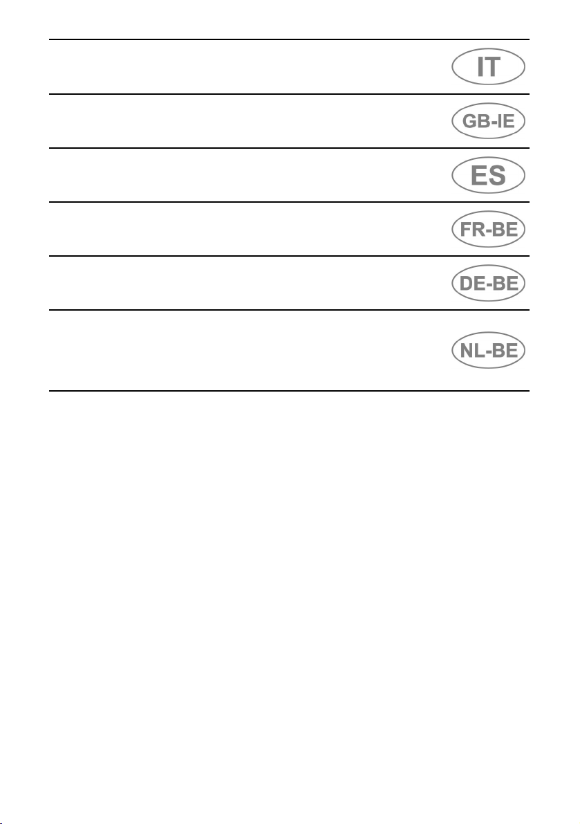
UNIONE PIANI COTTURA
Prima di eseguire il, montaggio dei piani
GAS, PIASTRE ELETTRICHE e PIANO
DI APPOGGIO, praticare nel piano top
un'apertura per l'incasso delle
dimensioni indicate in figura 1.
Nel caso di piani VETROCERAMICA,
FRIGGITRICE e BARBECUE o in
abbinamento con i piani sopra indicati
attenersi alle dimensioni indicate in
figura 2.
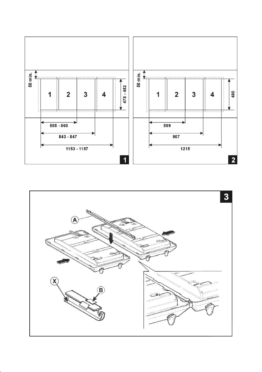
Il montaggio del corredo di unione deve
essere eseguito come segue (vedi fig.
3):
1. Mettere i piani di cottura uno
accanto all'altro, rovesciati;
2. Applicare sul listello di unione “A”
un leggero strato di silicone
trasparente in entrambi i lati interni
“X” su tutta la sua lunghezza e
inserirlo fra i piani di cottura;
3. Allineare e comprimere i piani al
listello;
4. Inserire i piani assemblati nel foro
praticato sul piano top, verificando
la perfetta unione del listello ai piani
(Fig.3);
5. Chiudere le alette di fissaggio “B”
aiutandosi con una pinza, in modo
che i lembi delle alette stringano i
lati dei piani;
6. Inserire i piani assemblati nel foro
praticato sul piano top, verificando
la perfetta unione del listello ai
piani;
7.
Togliere i piani di cottura dal foro ed
eseguire il fissaggio con la
guarnizione (vedere le istruzioni del
piano di cottura).
COMBINING HOBS
Before installing GAS hobs,
ELECTRIC PLATES and the COVER
TOP, make a hole in the top surface to
allow installation as shown in figure 1.
In case of CERAMIC, DEEP-FRYER
and BARBECUE hobs, installed on their
own or in combination with the fixtures
listed above, see figure 2 for hole
dimensions.
To install the combination kit, proceed
as follows (see fig. 4):
1. Place the hobs side by side, upside
down;
2. Apply a thin layer of transparent
silicone along the whole length of
both the inside edges “X” of the
joining strip “A”, and place it between
the hobs;
3. Align the hobs with the joining strip
and press them against it;;
4. Fit the assembled hobs into the hole
made in the top, checking that the
joining strip is perfectly snug against
the hobs (Fig. 3);
5. Close the fixing tabs “B” with the aid
of a pair of pliers, so that the edges
of the tabs grip the sides of the hobs
firmly;
6. Fit the assembled hobs into the hole
made in the top, checking that the
joining strip is perfectly snug against
the hobs;
7. Remove the hobs from the hole and
fix using the seal (see hob
instructions).
Page 4

UNIÓN DE LAS ENCIMERAS
Antes de montar las eneimras GAS,
PLANCHAS ELECTRICAS y
PLATAFORMA ESCURRIDORA, en la
plataforrna superior lleve a cabo un
agujero para empotrar según las
dimensiones indicadas en la figura 1.
En caso de encimeras
VITROCERAMICAS FREIDORA y
BARBACOA o de combinaciones con las
encimeras recién citadas, respete las
dimensiones indicadas en la figura 2.
El montaje del equipo de unión se debe
realizar de la siguiente manera (véase
fig. 3);
1. Coloque las encimeras invertidas
una junto a la otra;
2. Aplique sobre el tirante unión “A”,
Avant d'effectuer le montage des tables
de cuisson GAZ, PLAQUES
ELECTRIQUE et du PLAN D'APPUI,
faire une cavité dans le plan du dessus
pour l'encastrement (les dimensions
sont indiquées sur la fig. 1).
Pour les tables VITROCERAMIQUE,
FRITEUSE et BARBECUE qui peuvent
être unies aux tables indiquées cidessus, respecter les dimensions
reportées sur la fig. 2.
L'union des deux tables de cuisson doit être
effectuée de la façon suivante (voir fig. 4):
1. Mettre les tables l’une à côté de
2. Appliquer sur le listel de jonction “A”
una ligera capa de silicona en los
dos lados internos “X”, sobre toda
su longitud y acóplelo entre las
eneimeras;
3. Alinear y comprimir las encimeras
3. Aligner et comprimer les tables de
respecto del listón;
4. Insertar las encimeras ensambladas en
4. Introduire les tables assemblées dans
el agujero practicado en la bancada,
controlando la perfecta unión del listón
con las encimeras (Fig. 3);
5. Cerrar las aletas de fijación “B” con
5. Fermer les ailettes de fixation “ B ” à
ayuda de un par de pinzas, de
manera que los bordes de las
aletas queden apretando los lados
de las encimeras;
6. Insertar las encimeras ensambladas en
6. Introduire les tables assemblées dans
el agujero practicado en la bancada,
controlando la perfecta unión del listón
con las encimeras;
7.
Extraiga de nuevo las encimeras y
7. Enlever les tables de cuisson de la
realice su fijación con la junta
(véanse las instrucciones de la
encimera).
UNION DES TABLES DE
CUISSON
l'autre, renversées ;
une couche légère de silicone
transparent sur les deux côtés internes
“X” sur toute la longueur et le placer
entre les tables de cuisson;
cuisson au listel;
le trou fait sur le plan de travail en
vérifiant l'union parfaite du listel aux
tables (fig.3);
l'aide d'une pince, de façon à ce que les
bords des ailettes serrent les côtés des
tables;
le trou sur le plan du dessus en vérifiant
l'union parfaite du listel aux tables ;
cavité et fixer avec le joint (se
reporter aux instructions de la tabie
de cuisson).
Page 5

VERBINDUNG DER
KOCHMULDEN
Vor dem Einbau der GAS- und
ELEKTROEINBAUKOCHMULDEN und der
ABDECKUNGEN muß man die Arbeitsplatte
mit einer Einbauöffnung versehen, deren
Abmessungen den Angaben in Abbildung 1
entsprechen müssen.
Für den Einbau einer GLASKERAMIKEINBAUKOCHFLACHE, einer
EINBAUFRITEUSE oder eines
LAVASTEINGRILLS auch in Verbindung mit
den oben genannten Kochmulden muß man
die in Abb. 2 angegebenen Maße beachten.
Die montage des Verbindungssatzes ist
wie folgt aufzuführen (siehe Abb. 3):
1. Die Kochmulden mit der Unterseite
nach oben nebeneinander anordnen;
2. Die beiden lnnenseiten “X” des
Verbindungsprofils “A”, mit einer
dünnen Siliconeschicht versehen und
das Profil zwischen die Kochmulden
einfügen;
3. Die Kochmulden zueinander
ausrichten und an das Profil drücken;
4. Die miteinander verbundenen
Kochmulden in den Ausschnitt der
Arbeitsplatte einfügen und überprüfen,
ob die einwandfreie Verbindung
zwischen Profil und Kochmulden
aufrechterhalten bleibt (Abb. 3);
5. Die Befestigungsflügel „B“ mit Hilfe
einer Zange schließen, sodass die
Kanten der Flügel an den Seiten der
Kochmulden angedrückt sind;
6. Die miteinander verbundenen
Kochmulden in den Ausschnitt der
Arbeitsplatte einfügen und überprüfen,
ob die einwandfreie Verbindung
zwischen Profil und Kochmulden
aufrechterhalten bleibt.
7. Die Kochmulden aus dem Ausschnitt
nehmen und die Befestigung mit der
Dichtung (siehe die Anleitung der
Kochmulde) vornehmen.
Alvorens met de montage van de GAS-en
ELEKTRISCHE KOOKPLATEN en de
WEGZETPLAAT te beginnen een
inbouwopening maken in het werkblad met
afmetingen zoals vermeld in figuur 1.
Voor de VITRO KERAMISCHE platen,
de FRITEUSE en de BARBECUE, of bij
gebruik ervan in combinatie met de
bovengenoemde platen, de afmetingen
gebruiken zoals vermeld in figuur 2.
Het verbindingselement moet als volgt
worden gemonteerd (zie fig. 3):
1. De kookplaten ondersteboven
naast elkaar leggen;
2. Op de verbindingsstrip “A” een
lichte laag transparante siliconen
aanbrengen op de beide kanten “X”
over de gehele lengte en zo tussen
de kookplaten plaatsen;
3. Lijn de pinnen uit met de
aansluitstrip en druk de pinnen
ertegenaan;
4. Plaats de geassembleerde pinnen
in de opening in de bovenkant en
zorg dat de bevestigingsstrip goed
tegen de pinnen aan zit (Afb. 3);
5. Sluit de bevestigingslipjes “B” met
gebruikmaking van een buigtang en
zorg dat de randen van de lipjes de
zijkanten van de pinnen stevig
omsluiten;
6. Plaats de geassembleerde pinnen
in de opening in de bovenkant en
zorg dat de bevestigingsstrip goed
tegen de pinnen aan zit.
7. De kookplaten uit de opening halen
en definitief plaatsen met
gebruikmaking van de pakkingstrip
(zie de instructies van de
kookplaat).
SAMENVOEGEN
KOOKPLATEN
Cod. 913531071
 Loading...