


ELECTRONIC OVENS
EN INSTALLATION INSTRUCTIONS
FOURS ELECTRONIQUES
HORNOS ELECTRÓNICOS
FR INSTRUCTIONS D’INSTALLATION
ES INSTRUCCIONES PARA LA INSTALACIÓN

EN
TABLE OF CONTENTS PAG E
Introduction 2
Tools you will need 2
Power requirements 2
Choosing oven location 2
Steps for installation 2
Installation notes 3
Electrical supply 7
Wiring requirements 7
Connecting to 208 volt circuit 8
Electrical connections 9
3-Wire branch circuit (for US only) 9
4-Wire branch circuit (for US and Canada) 9
Final checklist 10
IMPORTANT: Save these instructions for the local electrical
inspector use.
INSTALLER: Please leave this manual with owner for future
reference.
WARNING
If the information in this manual is not followed exactly, a fire
or explosion may result causing property damage, personal
inju ry or death.
OWNER: Please keep this manual for future reference.
1
EN
Installation Instructions
Introduction
Please read these instructions COMPLETELY AND CAREFULLY.
They will save you time and effort and help to ensure optimum
oven performance.
Be sure to observe all WARNINGS. These installation
instructions are intended for use by a qualified installer.
In addition to these instructions, the oven shall be installed:
• In the United States, in accordance with the National Electric
Code/State and Municipal codes and/or local codes.
• In Canada, in accordance with Canadian Electric Code
C22.1-latest edition/Provincial and Municipal codes and/
or local codes.
These shall be carefully followed at all times.
NOTE: If installing your oven in canada please check to make
sure that you have a model with the us and canadian
listing
Mark, as shown above:
Mark as shown above means the oven complies with both US
and CANADIAN Standards.
Tools you will need
The following tools are needed to install your new oven:
• Tape measure and straightedge or ruler
• Pencil
• Phillips screwdriver
• Level
• Wire cutters and wire stripper
• Hand or saber saw
• 1” (2,5cm) Hole saw
• Drill and drill bit
• Safety gloves and goggles
• Volt meter (0-250VAC)
Packaging
Remove all tape and packaging before using the oven.
Destroy the packaging after unpacking the oven following the
rules in force in your town. Never allow children to play with
packaging material.
Power requirements
The oven must be supplied with the proper voltage and
frequency. The oven is manufactured to be connected to a
three-wire or four-wire, single phase, 120/240 Volt, 60 Hz AC
electrical supply on a separate circuit fused on both sides of the
line. If a 120/208 Volt circuit must be used, see Connecting to
120/208 Volt Circuit, in this manual.
A circuit breaker or time delay fuse, sized not to exceed
the circuit rating of the appliance specified on the rating
plate located on the frame behind the door of the oven is
recommended (see figure at page 4).
The oven must be supplied with copper or alumimum wires.
If aluminum wire is provided to connect oven to branch circuit,
UL listed connectors for joining copper and aluminum must be
used. Follow instructions provided with connectors.
It is recommended that you have the electrical wiring and hookup of your oven performed by a qualified electrician.
After installation is complete have the electrician show you
where the main disconnect is and which of the circuit breakers/
fuses are for the oven.
Choosing oven location
Carefully select the location where the oven will be placed.
The oven should be located for convenient use in the kitchen,
but away from strong drafts.
Strong drafts may be caused by open doors or windows, or
by heating and/or air conditioning vents or fans. Make sure
that electrical power can be provided to the location selected.
WARNING
If installed at an ambient temperature of less than 37°F (3°C),
the oven may present error F*0117. When the oven reaches
a higher ambient temperature, the error will disappear.
Steps for installation
The following pages provide the necessary information for
proper installation of the oven and are arranged as follows:
• Technical Data
• Installation Cutout Dimensions, Required Clearances and
Mounting instructions for:
- Under counter Installation, Single Oven
- Wall Installation, Single Oven
- Wall Installation, Double Oven
• Electrical Supply and Wiring Requirements, Programming
required if connecting to 120/208 Volt Circuit. Electrical
Connections for 3-wire or 4-wire Branch Circuit.
• Final Checklist
2
Installation Instructions
EN
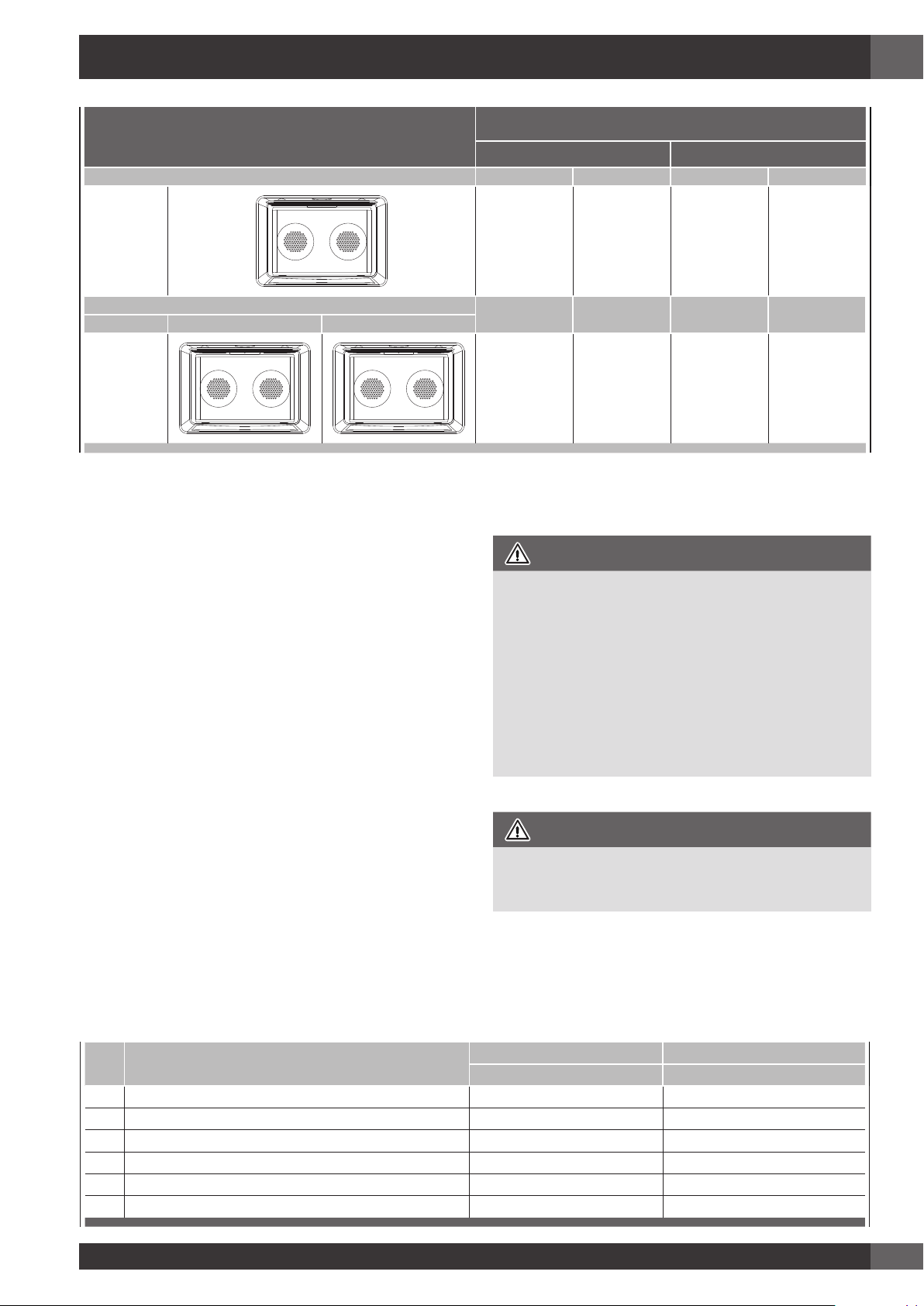
TECHNICAL DATA
For cutout dimensions see following section titled:
Preparing location
SINGLE OVEN Amperes kW Amperes kW
F7SP30*1
DOUBLE OVEN
UPPER CAVITY LOWER CAVITY
F7DP30*1
Installation notes
1. Do not slide oven across floor. Damage to floor covering or
floor could result.
Electrical Ratings and Maximum Connected Load
@ 120/240 Volts 60 Hz @ 120/208 Volts 60 Hz
15.4 3.70 16.8 3.50
Amperes kW Amperes kW
31.2 7.50 30.3 6.30
WARNING
2. The oven support surface must be a minimum 3/4” (2cm)
thick plywood platform.
For single ovens, it must support 202 pounds.
For double ovens, it must support 379 pounds. The
platform must be solid, level and flush with the bottom of
the cabinet cut out.
3. Use extreme caution when moving or installing the oven. It
is very heavy.
DO NOT LIFT THE OVEN BY THE DOOR HANDLE, remove
the door for easier handling and installing.
See REMOVING THE DOOR in the maintenance section of
the Use Care Manual.
4. Be very careful when moving or installing the oven to avoid
damage to the oven frame or damage to the cabinets.
5. Be sure to level the oven. An oven that is not level may
provide poor or inconsistent baking results.
6. Be careful when placing oven. DO NOT pinch the conduit
between the oven back.
Before installing or removing, turn power OFF at the service
panel. Lock service panel to prevent power from being
turned ON accidentally.
Securely fasten oven to cabinet using the screws provided.
Failure to do so could result in oven moving or tipping during
use and causing damage to the oven or cabinets or personal
injury.
Know how to disconnect the power to the oven at the circuit
breaker or fuse box in case of an emergency.
CAUTION
Unit is heavy and requires at least two people or proper
equipment to move.
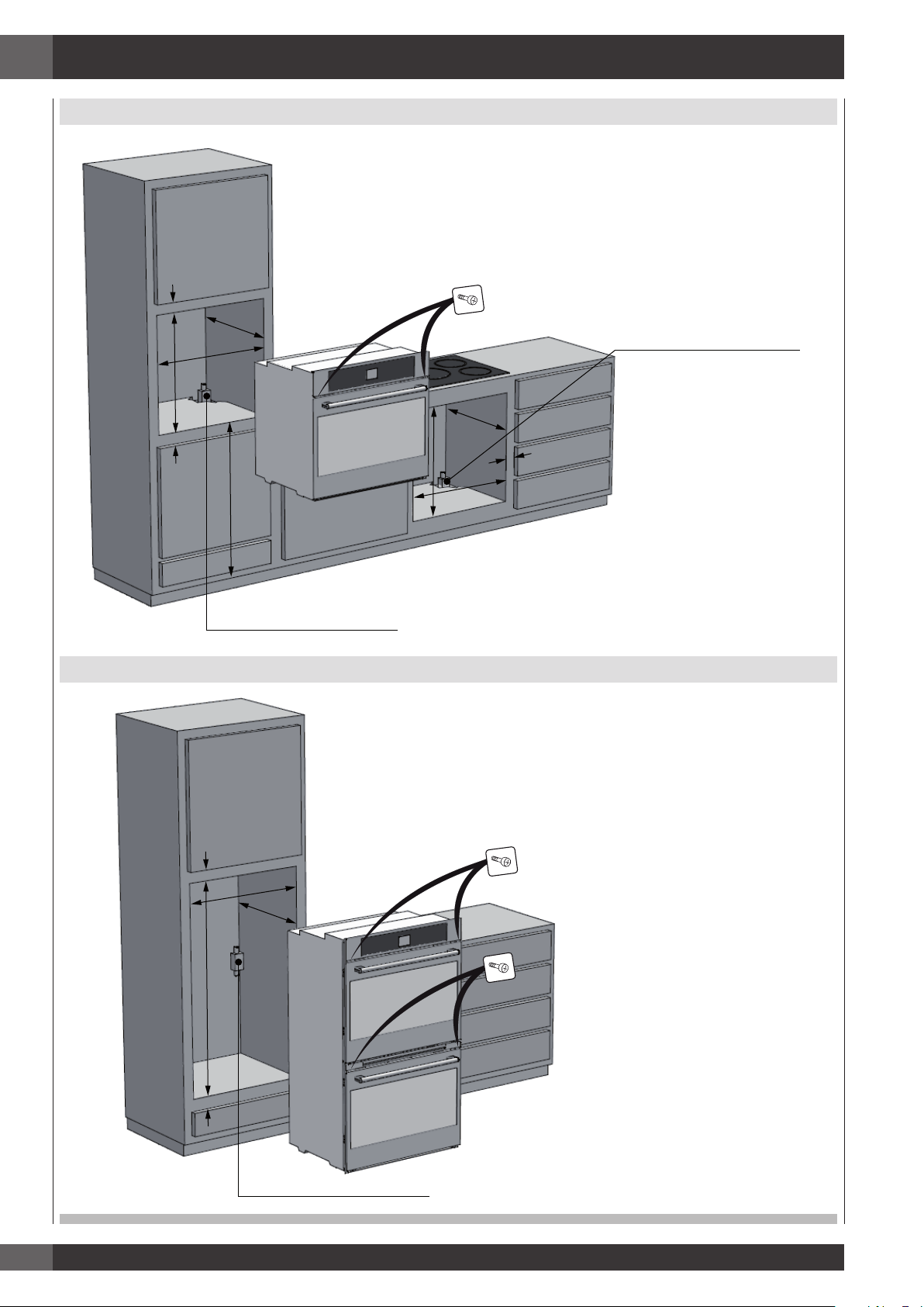
Ltr. DIMENSION
A
Cutout Width 28 7/16” (72.2 cm) 28 7/16” ( 72.2 cm)
B
Cutout Depth 24” (61.0 cm) 24” ( 61.0 cm)
C
Cutout Height 27 3/8” (69.5 cm) 50” (127.0 cm)
D
Floor Bottom of Cutout 34” (86.5 cm) N/A
E
Minimum Spacing 1/2” min ( 1.3 cm) 1/2” min ( 1.3 cm)
F
Minimum Spacing 3/4” min ( 1.9 cm) 1” min ( 2.5 cm)
SINGLE DOUBLE
30” 30”
3
EN
Installation Instructions
WALL OR UNDER COUNTER INSTALLATION, SINGLE OVEN
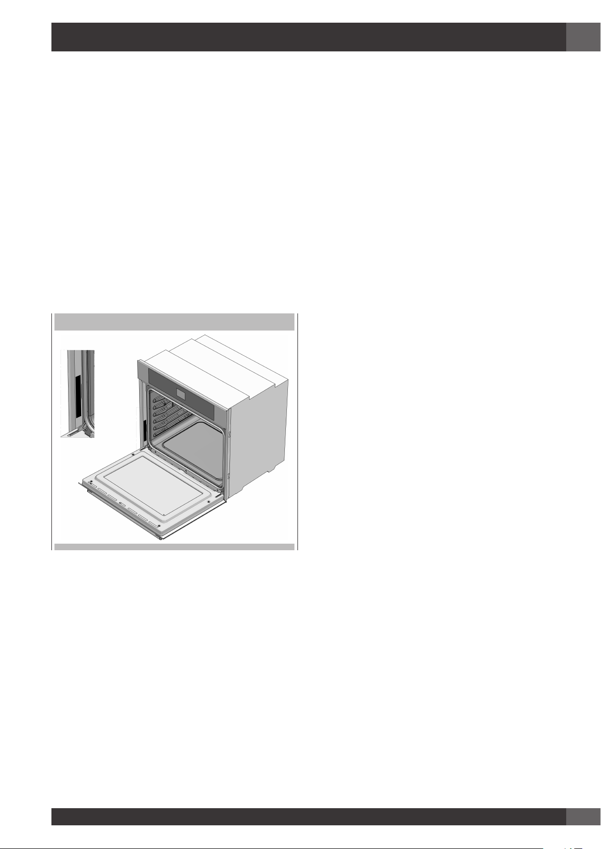
Secure oven to cabinet using the screws provided.
Screws should be inserted through the mounting holes in the positions
indicated in the frame (open door to see frame and mounting holes).
Do not over tighten screws.
F
B
A
C
Electrical supply junction box
B
E
D
Electrical supply junction box
F
A
C
E
A
WALL INSTALLATION, DOUBLE OVEN
Secure oven to cabinet using the screws provided.
Screws should be inserted through the mounting holes in the positions
indicated in the frame (open door to see frame and mounting holes).
Do not over tighten screws.
B
C
E
Electrical supply junction box
4

Installation Instructions
FLUSH INSTALLATION
Mounting strip
H
EN
Mounting strip
F
G
Finished sides
(same finish like the cabinet)
Ltr. DIMENSION
F
Cutout Width 30 1/16” (76.4 cm) 30 1/16” ( 76.4 cm)
G
Cutout Height 28 1/32” (71.2 cm) 51” (129.5 cm)
H
Visible part of the mounting strips 3/4” ( 1.9 cm) 3/4” ( 1.9 cm)
SINGLE DOUBLE
30” 30”
Finished sides
(same finish like the cabinet)
F
G
5

EN
(129 cm)
50 3/4”
(75.4cm)
29 3/4”
(68 cm)
26 3/4”
26 3/4”
(68 cm)
27 7/8”
(70.7 cm)
(75.4 cm)
29 3/4”
Installation Instructions
26 3/4”
(68 cm)
PRODUCT-DIMENSIONS
26 3/4”
(68 cm)
50 3/4”
(129 cm)
27 7/8”
(70.7 cm)
1”
(2.5 cm)
(2 cm)
(75.4 cm)
3/4”
7 7/8”
(20 cm)
29 3/4”
7/8”
(2.2 cm)
49 3/4”
(126.2 cm)
1”
(2.5 cm)
23 1/8”
(58.7 cm)
29 3/4”
(75.4cm)
7/8”
(2.2 cm)
3/4”
(2 cm)
7 7/8”
(20 cm)
17”
(43 cm)
17”
27 1/8”
(69 cm)
3/4”
(1.9 cm)
6
(43 cm)
23 1/8”
(58.7 cm)
3/4”
(1.9 cm)
Installation Instructions
EN
Electrical supply
Before installing the oven have a qualified electrician verify
that your home is provided with adequate electrical service
and that the addition of the oven will not overload the branch
circuit on which it is to be installed.
A separate three-wire or four-wire single phase, 240 Volt, 60
Hz, or a 208 Volt, 60Hz branch circuit is required.
NOTE: For use with 208 v, 60 hz supply voltage, see
connecting to 208 volt circuit.
For hook-up of the oven you will need to have an approved
junction box installed where it will be easily reached through
the front of the cabinet where the oven will be located. The
oven has 3 feet of conduit.
Allow two to three feet of slack in the line so that the oven can
be moved if servicing is ever necessary.
DO NOT shorten the flexible conduit.
LOCATION OF RATING PLATE
Wiring requirements
When making the wire connections, use the entire length of the
conduit provided (3 feet). The conduit must not be cut.
Before making connections make sure the power is off and
read and observe the following:
1. A separate three-wire or four-wire, single phase, 240 Volt,
60 Hz or 208 Volt, 60 Hz branch circuit is required for the
oven.
2. The oven must be connected with Copper or Aluminum wire.
3. In the United States:
Wiring must conform to the National Electrical Code,
ANSI/NFPA No. 7 latest edition. You can obtain a copy
of the National Electrical Code by writing to: National
Fire Protection Association Batterymarch Park Quincy, MA
02269
In Canada:
Wiring must conform to Canadian Electrical Code C22.1latest edition. You can obtain a copy of the Canadian
Electrical Code by writing to: Canadian Standards
Association 178 Rexdale Boulevard Rexdale (Toronto),
Ontario, Canada M9W 1R3
4. Wire size (Copper or Aluminum wire) and connections must
be suitable for the rating of the appliance as per the National
Electrical Code requirements. The flexible armoured cable
extending from the oven should be connected directly to the
junction box.
5. The junction box should be located so as to allow as much
slack as possible between the junction box and the oven so
it can be moved if servicing is ever required.
6. A U.L. listed conduit connector must be provided at each
end of the power supply cable.
7

EN
SETUP
SERVICE
EVENT LOGS
MAIN VOLTAGE
SYSTEM
DEMO
OM 15
MAIN VOLTAGE
240
ADVANCED
Installation Instructions
Connecting to 208 volt circuit
This option is provided for areas where standard 240 Volt
service is not available. This option must be accessed with
the oven connected to power source, and using the following
sequence:
a) Press the
arrow and confirm with the
b) From the “SYSTEM” menu select the “MAIN VOLTAGE”
option and confirm again with the
SET
key and select the option by means of the
START
key.
START
key.
WARNING
ELECTRICAL SHOCK HAZARD
• The electrical power to the oven branch circuit must be
shut off while line connections are being made.
• Do not use an extension cord with this appliance.
• Electrical ground is required on this appliance. The free
end of the green wire (the ground wire) must be connected
to a suitable ground. This wire must remain grounded to
the oven.
• If cold water pipe is interrupted by plastic, non metallic
gaskets, union connections or other insulating materials,
DO NOT use for grounding.
• DO NOT ground to a gas pipe.
• DO NOT have a fuse in the NEUTRAL or GROUNDING
circuit. A fuse in the NEUTRAL or GROUNDING circuit
could result in an electrical shock.
• Check with a qualified electrician if you are in doubt as to
whether the appliance is properly grounded.
c) By means of the arrow, select the “208V” option and
confirm with the
START
.
• Failure to follow these instructions could result in serious
injury or death.
CAUTION
Do not repair or replace any part of the appliance unless
specifically recommended in the manual. All other servicing
should be done by a qualified technician. This may reduce
the risk of personal injury and damage to the oven.
Never modify or alter the construction of the appliance by
removing panels, wire covers, screws, or any other part of
the product.
The voltage setting is stored and kept even after a long
power-off.
8

Installation Instructions
Electrical connections
Be sure your appliance is properly installed and grounded by a qualified technician. Ask your dealer to recommend a qualified
technician or an authorized repair service.
This appliance is manufactured with a green GROUND wire connected to the oven chassis. After making sure that the power has
been turned off, connect the flexible conduit from the oven to the junction box using a U.L. listed conduit connector. Figures A and
B and the instructions provided below present the most common way of connecting the ovens.
Your local codes and ordinances, of course, take precedence over these instructions. Complete electrical connections according to
local codes and ordinances.
“WARNING” Risk of Electric Shock, frame grounded to neutral of appliance through a link.
Grounding through the neutral conductor is prohibited for new branch-circuit installations (1996 NEC); mobile homes; and
recreational vehicles, or in an area where local codes prohibit grounding through the neutral conductor. For installations where
grounding through the neutral conductor is prohibited:
• Disconnect the ground from the neutral at free end of conduit;
• Use grounding terminal or lead to ground unit; and
• Connect neutral terminal or lead to branch circuit neutral in usual manner.
EN
3-Wire branch circuit (for US only)
Refer to Figure A, where local codes allow the connection of
GROUND wire from the oven to the branch circuit NEUTRAL
wire (gray or white colored wire):
• If local codes permit, connect the green GROUND wire
from the oven and the white wire from the oven to the
branch circuit NEUTRAL wire (gray or white colored wire).
• Connect the red and black leads from the oven to the
corresponding leads in the junction box.
GROUNDED NEUTRAL
A
Junction box
Red wires
White wires
Cable from
power supply
4-Wire branch circuit (for US and Canada)
Refer to Figure B:
• Disconnect ground from neutral at free end of conduit.
• Connect the green GROUND wire from the oven to the
GROUND wire in the junction box (bare or green colored
wire).
• Connect the red and black leads from the oven to the
corresponding leads in the junction box.
• Connect the white wire from the oven to the NEUTRAL (gray
or white) wire in the junction box.
UNGROUNDED NEUTRAL
B
Junction box Cable from
power supply
Red wires
White wires
Bare or
green wire
Cable
from oven
Black wires
UL listed conduit
connector
Bare or
green wire
Cable
from oven
Black wires
UL listed conduit
connector
9

EN
Installation Instructions
Final checklist
To prevent improper connections leading to damage of
electrical components and so voiding the warranty, the
following steps must be performed:
1. Check the electrical requirements and make sure you have
the correct electrical supply and that the oven is properly
grounded.
2. Turn on the power supply to the oven.
3. Check power at the junction box wires using a voltmeter
having a range of 0-250 VAC.
If you have installed the oven for use on 240 Volt supply,
you should find that the voltage reading between the black
and red wires (Line to Line) should be 220 to 240 Volts.
If you have modified the oven(s) for use on 208 Volt, the
voltage reading between the black and red wires should
be 190 to 208 Volts.
4. Test the oven mode. Select the
and Care Manual for detailed operation instructions.
5. Verify that the oven light comes on and the oven begins
to preheat.
6. Test the door lock. Set the
the door locks when the lock icon appears in the display.
7. If installing a double oven, test the second oven as well.
8. To check the other oven functions refer to the “Using the
Oven Controls” section of the USE AND CARE MANUAL.
9. If the oven is working properly, turn off the power supply
to the oven.
10. Place the cover on the junction box and make sure the
cover is securely fastened and turn on the power to the
oven.
Leave these INSTALLATION instructions as well as the USE AND
CARE MANUAL with the owner.
BAKE
SELF CLEAN
mode. See the Use
mode. Confirm that
10

Note / Note / Nota
11

Note / Note / Nota
12


DOC COD. 09X9400 - 09-19
 Loading...