

Page 1
SMR130G SMR315G
USER AND MAINTENANCE MANUAL
Page 2
Rev. 01
User and maintenance manual
2
Smeg S.p.A. – Instruments Division
Via Leonardo da Vinci, 4
42016 Guastalla (RE)
www.smeg-instruments.com
READ CAREFULLY
This manual constitutes an integral part of the refrigerating unit.
It must be kept intact and at hand for the entire life cycle of the machine. It is necessary to read the
following manual carefully prior to using the device. Failure to read or thoroughly comprehend the
instructions in this manual may cause the device to malfunction and present hazards to the user.
Machine installation, maintenance, and repair operations must be performed
by authorized technical staff.
Repair operations performed by unauthorized staff, besides leading
invalidating the product warranty, can be source of danger for the user.
In case of replacement, an original spare part must be used.
If the device was not used in accordance to the instructions presented in this
manual, the product may no longer be covered by warranty and the safety of
this device could be compromised.
The producer declines all liability for any use that differs from what indicated in
the present manual.
The refrigerating unit has not to be used in presence of explosive gases or near
sources with high electronic or magnetic fields.
The content of this manual is for information purposes only. The content and the equipment
described here may be subject to change without notification. The colours used in photographs of
the product (finishing panels), in diagrams and in screenshots are all purely guideline.
Page 3
Rev. 01
User and maintenance manual
3
SUMMARY
Products applicable to this manual ....................................................................................................................... 4
Table of capacity and dimensions ........................................................................................................................ 4
Table of technical specifications ........................................................................................................................... 5
Standard and optional fitting ................................................................................................................................. 5
1 STANDARDS AND GENERAL WARNINGS .............................................................................................. 6
1.1 Certification ............................................................................................................................................. 6
1.2 Initial recommendations .......................................................................................................................... 6
1.3 Precautions for use ................................................................................................................................. 9
1.4 Aim, content and intended user of this manual ...................................................................................... 9
1.5 General safety regulations .................................................................................................................. 100
1.6 Customer responsibilities...................................................................................................................... 10
1.7 Customer service requests ................................................................................................................... 11
1.8 Ordering of spare parts ......................................................................................................................... 11
1.9 Aim and intended use of device ........................................................................................................... 11
1.10 Unsuitable conditions for use ............................................................................................................... 11
2 INSTALLATION ........................................................................................................................................ 12
2.1 Transport and handling ......................................................................................................................... 12
2.2 Positioning ............................................................................................................................................ 12
2.3 Wiring and electrical hook-up ............................................................................................................... 13
2.4 Set-up operations ................................................................................................................................. 13
2.5 Re-installation ....................................................................................................................................... 14
2.6 Scrapping and disposal ........................................................................................................................ 14
3 OPERATION ............................................................................................................................................. 15
3.1 Safety and accident prevention ............................................................................................................ 15
3.2 Safety dataplates and guards ............................................................................................................... 15
3.3 Operating limits ..................................................................................................................................... 15
3.4 Environmental storage conditions ........................................................................................................ 15
4 USER INSTRUCTIONS ............................................................................................................................ 16
4.1 Appliance start-up ................................................................................................................................. 18
4.2 Functions .............................................................................................................................................. 18
4.3 Control panel ...................................................................................................................................... 200
4.4 Alarm codes .......................................................................................................................................... 26
4.5 Troubleshooting .................................................................................................................................... 27
5 ROUTINE MAINTENANCE ...................................................................................................................... 28
5.1 Cleaning of the refrigerator ................................................................................................................... 28
5.2 Cleaning of the interior and exterior ..................................................................................................... 29
5.3 Cleaning of the condenser .................................................................................................................... 29
5.4 Precautions for prolonged disuse ......................................................................................................... 30
6 ELECTRICAL DIAGRAM .......................................................................................................................... 31
7 AFTER-SALES SERVICE .............................................................. Errore. Il segnalibro non è definito.3
Page 4
Rev. 01
User and maintenance manual
4
Products applicable to this manual
The present manual is exclusively valid and applicable to the following SMEG product series.
Laboratory refrigerators SMR series
Adjustable temperature control range: highest T = +10°C, lowest T = +2°C
Models:
SMR130G
SMR315G
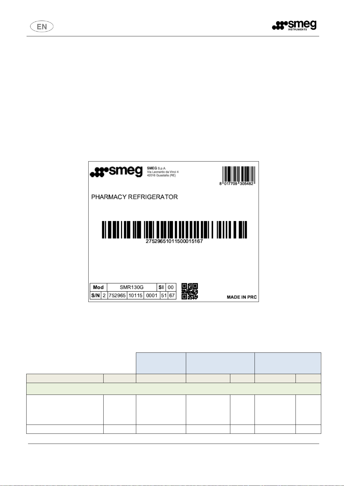
All relevant data referring to SMEG products can be found on the data label visible on the side part of the
cabinet. Here is an example of the label:
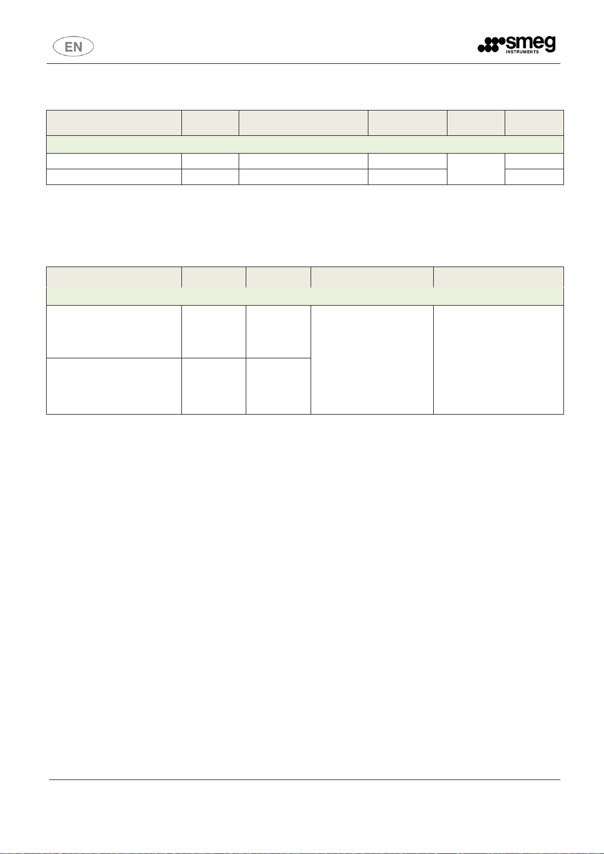
Table of capacity and dimensions
Internal
dimensions
External dimension and
unit net weigth
Dimensions of
packaging and shipping
weight
MODEL
Volume (L)
LxDxH (mm)
LxDxH (mm)
Kg
LxDxH (mm)
Kg
Laboratory refrigerators – SMR series
SMR130G
130
554 x 450 (318*) x
383 (205*)
*smaller dimensions
on the lowest part of
the chamber
650 x 625 x 810
51
707 x 687 x 870
61
SMR315G
315
580 x 533 x 1122
650 x 673 x 1762
87
727 x 737 x1785
99
Page 5
Rev. 01
User and maintenance manual
5
Table of technical specifications
MODEL
Volume (L)
Voltage (V) / Frequency (Hz)
Rated Power
Absorption (W)
Gas
Q.ty (Kg)
Laboratory refrigerators – SMR series
SMR130G
130
230 / 50
150 (164 input)
R600a
0,055
SMR315G
315
230 / 50
250 (277 input)
0,022
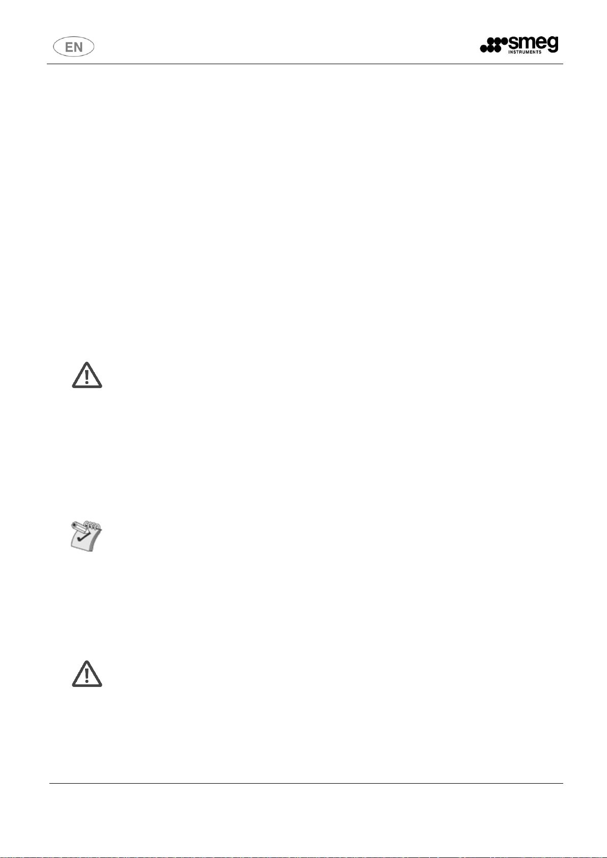
Standard and optional fitting
MODEL
Shelves
Drawers
Standard fitting
Optional accessories
Laboratory refrigerators – SMR series
SMR130G
2 + 1 lower
basket
-
Shelves
Wheels + adjustable feet
Schuko plug
Panel control board with
alarm system
Dry contact remote alarm
USB port
Datalogger
Backup battery
Pass-through hole
Safety thermostat +2°C
Additional shelves
SMR315G
4 + 1 lower
basket
-
Page 6
Rev. 01
User and maintenance manual
6
1 STANDARDS AND GENERAL WARNINGS
1.1 Certification
All appliances are produced in accordance with European Community Regulations applicable at the
time of its appearance on the market. All appliances are manufactured in accordance with European
Directive 2014/35/UE, 2014/30/UE and following integrations and according to safety requirements
for electrical equipment for laboratory use (IEC 61010-1).
1.2 Initial recommendations
READ THE PRESENT INSTRUCTION MANUAL CAREFULLY
This manual constitutes an integral part of the machine.
It must be kept intact and at hand for the entire life cycle of the machine.
It is necessary to read the following manual carefully prior to using the device.
Failure to read or thoroughly comprehend the instructions in this manual may cause the device to
malfunction and present hazards to the user.
Machine installation, maintenance, and repair operations must be performed by
authorized technical staff.
Repair operations performed by unauthorized staff, besides leading invalidating the
product warranty, can be source of danger for the user.
In case of replacement, an original spare part must be used.
If the device was not used in accordance to the instructions presented in this
manual, the product may no longer be covered by warranty and the safety of this
device could be compromised.
The producer declines all liability for any use that differs from what indicated in the
present manual.
The product warranty does not cover faulty parts due to negligence, inappropriate
use, or failure to comply with the instructions of the device operations; incorrect
installation or maintenance; repair and maintenance operations performed by
unauthorized staff or with non-original spare parts; transportation damages; and any
circumstance that cannot be ascribed to the device manufacturing defects.
Moreover, the warranty does not cover operations related to installation and
connection of alimentation and drain systems as well as maintenance operations
provided in the instruction booklet.
The installation of any accessory on the machine must be performed by authorized
technical staff.
To request further information about accessories: contact your trusted seller and/or
the authorized technical assistance, using the contact details provided in this
manual.
The content of this manual is for information purposes only. The content and the equipment
described here may be subject to change without notification.
Page 7
Rev. 01
User and maintenance manual
7
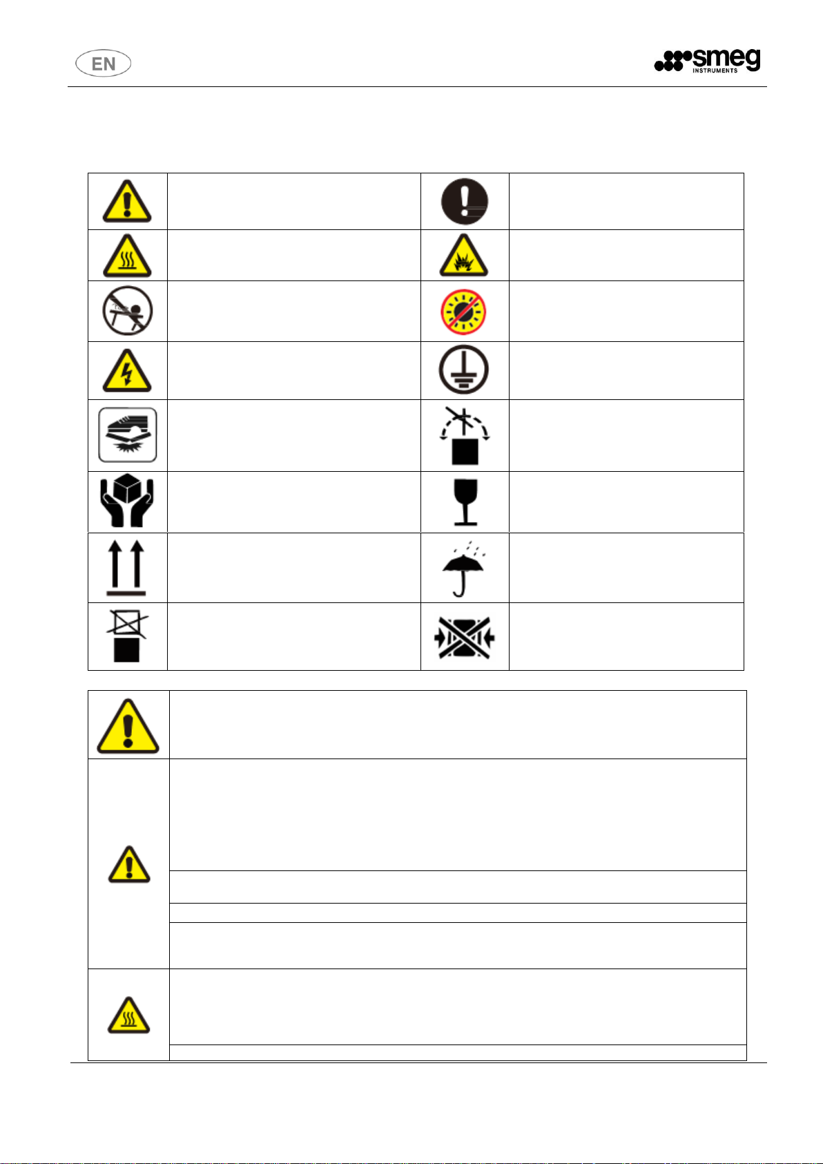
WARNING
Failure to observe WARNING signs could result in
a hazard to personnel possibly resulting in serious
injury or death.
CAUTION
Failure to observe WARNING signs could
result in injury to personnel and damage to
the unit and associated property.
CAUTION HOT
The sign inform the users about the danger of
burns for high temperature.
DANGER OF EXPLOSION
The sign inform the danger of the application of
volatile, explosive chemical substances.
NO TILTING
STAY OUT OF SUN
BEWARE OF ELECTRIC SHOCK!
Dangerous voltage may cause personal injury!
Please disconnect the power supply before repair.
GROUNDING MARK
NO TRAMPLING EQUIPMENT
NO TUMBLING TRANSPORT
PACKAGES
PRECISION INSTRUMENTS
HANDLE WITH CARE
THE CONTENTS MUST BE
PLACED AT THE ARROW
FEAR OF THE RAIN
NO STACKING
NO CLAMPING
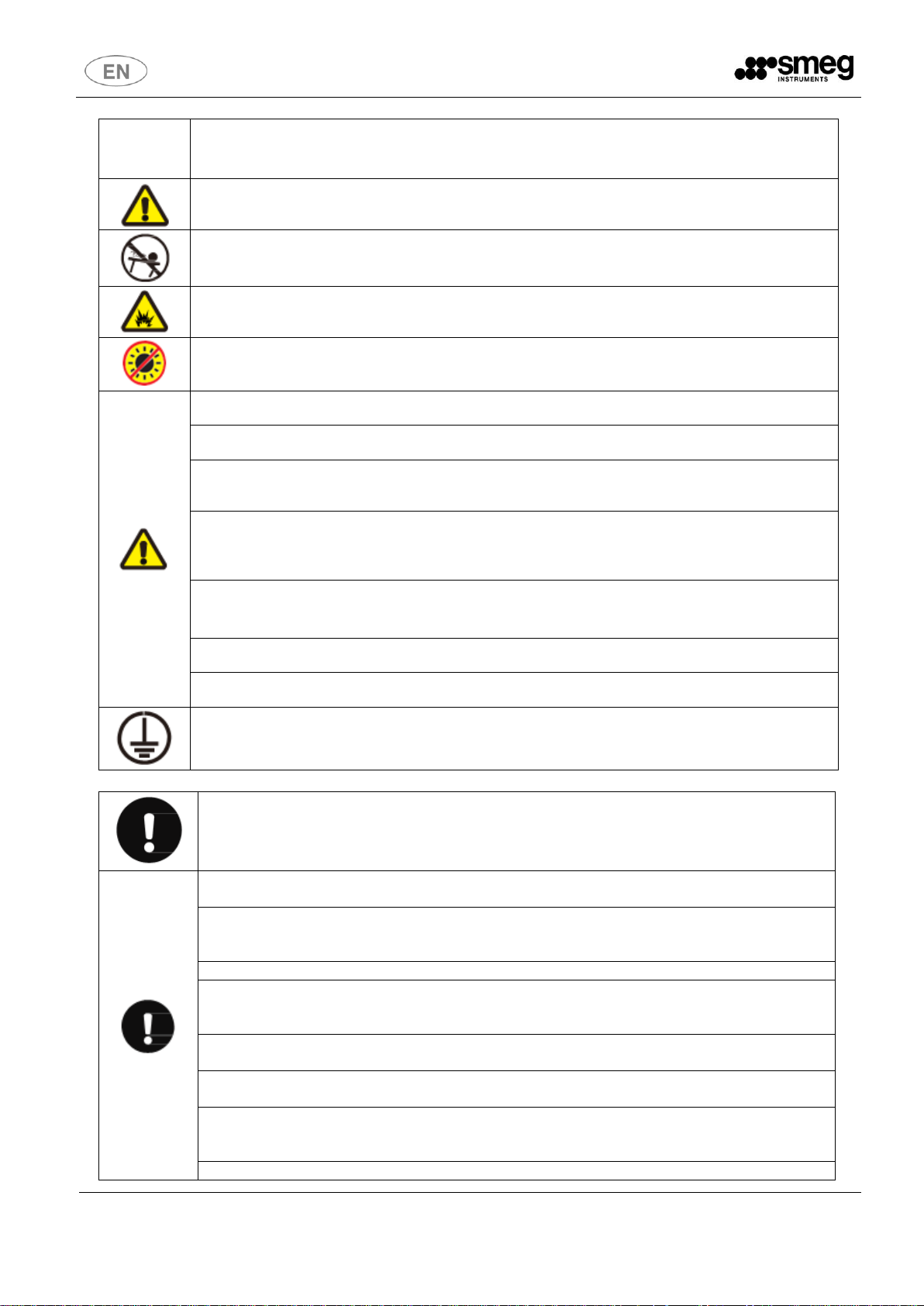
WARNING
Failure to observe WARNING signs could result in a hazard to personnel possibly
resulting in serious injury or death.
As with any equipment that uses CO2 gas, there is a likelihood of oxygen depletion in
the vicinity of the equipment.
It is important that you assess the work site to ensure there is suitable and sufficient
ventilation.
If restricted ventilation is suspected, then other methods of ensuring a safe
environment must be considered. These may include atmosphere monitoring and
warning devices.
Do not touch any electrical parts such as the power supply plug or any switches with
a wet hand. This may cause electric shock.
Only qualified and authorised engineers shall install the unit.
Be sure to install the unit on a sturdy floor. If the floor is not strong enough or the
installation site is not adequate, this may result in injury from the unit falling or tipping
over.
Carefully with the power cord to avoid short circuit or open circuit. When removing the
plug from the power supply outlet, grip the power supply plug, not the cord. Pulling the
cord may result in electric shock or fire by short circuit. Don't make the power line pack
and pressed by furnish or heavy goods. Also please don't close to the compressor and
heat source.
Please insert the power plug firmly to avoid leakage.
Page 8
Rev. 01
User and maintenance manual
8
Use a power supply outlet with ground (earth) to prevent electric shock. If the power
supply outlet is not grounded, it will be necessary to install a ground by qualified
engineers.
Make sure a dedicated power source is used as indicated on the rating label attached to
the unit. Out of the rate, should install a property transformer and a proper voltage
stabilizer for safe operation.
Be sure to install the unit on a sturdy floor, no shaking and tilting.
Never install the unit in a flammable or volatile location. This may cause explosion or fire.
Never install the unit in a humid place or outdoor or a place where it is likely to be basked
straightly. Deterioration of the insulation may result which could cause current leakage
or electric shock.
Do not place the device lateral tilt, do not impact the device; the device is equipped with
refrigeration systems, roll or shock will easily damage the device.
Be sure to install the device in a dry dust-free environment to avoid overheating, short
circuit and other dangers.
If there is an unexpected sound, smell, smoke when the power is turned on, unplug the
power and contact the manufacturer or supplier. Continued abnormal operation may
cause electric shock or fire.
Make sure to put the device in a dry and ventilated location, to ensure that equipment
vents and wall surface of the instrument or other items have not been blocked; Do not
use the device in a poorly ventilated environment, or the equipment may be damaged by
the release of heat.
Never disassemble, repair, or modify the unit by yourself.
Any such work carried out by an unauthorized person may result in fire or injury due to a
malfunction. Smeg will be no responsible for such work.
Use this unit in safe area when treating the poison, harmful or radiate articles. Improper
use may cause bad effect on your health or environment.
Never place the unit through on a gas pipe, water main, telephone line or lightning rod.
Such grounding may cause electric shock in the case of an incomplete circuit.
Use a power supply outlet with ground (earth) to prevent electric shock. If the power
supply outlet is not grounded, it will be necessary to install a ground by qualified
engineers.
CAUTION
Failure to observe WARNING signs could result in injury to personnel and damage
to the unit and associated property.
Ultra-low temperature device is not available to store liv ing things or other critical
articles which is not suitable for low temperature storage.
The temperature inside the device is very low during the normal working. Do not
touch the interior surface of the chamber or the object inside without wearing
protective gear.
Always disconnect the power plug when the unit is not used for long periods.
Make sure to prepare a safety check sheet when you request any repair or
maintenance for the safety of service personnel. Be sure to check set point of the
controller before restarting the device.
Always hold the handle when closing the door. This will reduce the likelihood of a
trapped finger.
Keep the key properly avoiding the children take it to open the door which may
result in unexpected injury.
Select a level and sturdy floor for installation. This precaution will prevent the unit
from tipping. Improper installation may result in water spillage or injury from the
unit tipping over.
Check the filter mentioned in this manual and clean it properly and periodically.
Page 9
Rev. 01
User and maintenance manual
9
A dusty filter may cause temperature rise or failure.
Do not tilt the unit more than 45 degrees when moving the unit.
All transportation shall be done carefully.
1.3 Precautions for use
• When the device is running, the front part of the device may get hot. This is not a
malfunction: In order to prevent dew condensation around the case body, a heated anticondensation tube is installed in the cryogenic storage case.
• Before putting the items in the device, please make sure the temperature inside the
chamber has reached the set temperature, and then put the items in batches. Add no more
than 1/3 of the container volume each time, in case the temperature rises too much.
• The temperature display value shows the temperature of temperature sensors inside the
device. Although the displayed temperature may sometimes differ from the actual
temperature in the center of the device, it will get close to the real temperature gradually.
• A through-hole is installed on the side or back of the device to allow test lines to exit the test
box. After drawing out the test lines, be sure to re-plug the test hole with insulating material,
otherwise the temperature inside the box will not be completely lowered, resulting in
condensation around the outside of the hole.
• Clean the device with diluted neutral detergent. Do not use brushes, acid, gasoline, soap,
polish or hot water to clean the frozen storage container, as these materials may damage
the surfaces and plastic and rubber components.
• After a period of operation, mostly if the frequency of door openings is high, a layer of frost
may form on the inner wall and the inner door. If the frost layer is too thick, it will affect the
insulation effect of the device and increase the power consumption. Therefore, after a
period of time, when the frost layer reaches about 5mm, it should be defrosted with the
defrost shovel included.
• Please remove the frozen items in the device and put them in a suitable storage place
before defrost, so as to avoid the damage of goods for temperature rise.
• There are many cooling coils on the back and side of the inner wall. Don't use sharp objects
such as knives, ice chisel, or screwdrivers to remove the frost on the inner wall. Be careful
not to scratch the inner wall when defrosting, otherwise it will cause a failure of the device.
• Cut off the power when the refrigerated storage box will not be used for a long time.
1.4 Aim, content and intended user of this manual
This manual has been prepared with the objective to supply all instructions required for the correct
use of the appliance and to keep it in optimal condition. It also contains important user safety
information.
The following professional roles are explained in order to define the responsibilities of each
involved parties.
Installer: a qualified technician, authorised by the manufacturer, who installs the appliance in
accordance with the instructions herein contained.
Page 10
Rev. 01
User and maintenance manual
10
User: the person who, after having read this manual carefully, uses the appliance in accordance
with the intended specification of use described in this manual.
User’s responsibilities:
▪ ensure that the product is kept at suitable temperatures without exceeding +38° of ambient
temperature;
▪ be aware of the regulations governing the conservation of products to refrigerate and to
observe any whatsoever hygiene indications that may be applicable.
The user is obliged to read carefully the manual and refer to its information at all times. Particular
attention must be paid to the contents of heading 1.4 General safety warnings.
Routine maintenance technician: qualified operator able to perform routine maintenance of the
appliance by following the instructions in this manual (can be the customer too e).
Service engineer: qualified technician, authorised by the manufacturer to perform extraordinary
maintenance of the appliance.
Installer and service engineer must always be authorized by the manufacturer.
The manufacturer declines any whatsoever responsibility in case of improper use of the appliance
deviating from the reasonably construed intended use, and for all operations carried out that are
not in compliance with the instructions reported in the manual.
This manual must be stored in an accessible and known place for all operators (installer, user,
routine maintenance technician, service engineer).
1.5 General safety regulations
Read this manual carefully and follow the prescriptions contained herein.
The user assumes full responsibility in case of operations carried out without observing the
instructions in the manual. None of SMEG products are designed to work in presence of flammable
gases or solvent that may easily burn, hence keep off the unit of any of these situations.
Primary general safety regulations:
▪ do not touch the unit with wet hands and/or feet
▪ do not use the appliance with bare feet
▪ do not insert screwdrivers or other pointed objects between guards or moving parts of the
appliance
▪ do not pull the power cord to disconnect the appliance from the electrical mains
▪ make sure that the appliance is not used by unsuitably qualified persons
▪ before performing any cleaning or maintenance on the appliance disconnect it from the
electrical mains by switching off the main switch and extracting the plug
▪ in case of faults or malfunctions, switch off the appliance and do not attempt to repair it by
yourself. All service and repair operations must be performed exclusively by a suitable
authorized engineer.
This symbol on the equipment indicates a situation of danger. Pay attention
and read carefully what it refers to.
1.6 Customer responsibilities
The customer is required to:
▪ execute the electrical connection of the appliance
Page 11
Rev. 01
User and maintenance manual
11
▪ prepare the place of installation
▪ provide consumable materials for cleaning
▪ perform routine maintenance
In the case of power failures or malfunctions do not open the doors in order to maintain as much
as possible the internal temperature. If the problem persists for more than few hours, move the
contents to a more suitable place.
1.7 Customer service requests
For all technical problems and any requests for technical service, refer exclusively to your local
dealer, pointing out model and serial number.
1.8 Ordering of spare parts
Orders of spare parts should be made by consulting the part reference code and the serial number
of your appliance. Consult your dealer.
The user must consult the dealer or the manufacturer, as the case of SMEG
appliances require original spare parts, failing of which product certification
decades.
1.9 Aim and intended use of device
The appliance is conceived for the use in hospitals, laboratories, pharmacies and industries and it
is intended solely for the preservation of laboratories and medical products, which request various
controls and warning in case of sudden alteration of temperature.
In particular: medicinal products; laboratory samples; thermo-sensitive chemical reactants
It is absolutely not intended for storage of flammable materials, gas or explosive materials
Products must be stored in order to ensure efficient air circulation inside the
appliance and shall not come out of the shelf perimeter.
All uses except authorized used of the appliance shall be construed as “improper
use” for which the manufacturer declines all responsibility.
1.10 Unsuitable conditions for use
The appliance must not be used exposed to bad weather, with adapters, multiple sockets or
extension leads, in an explosive atmosphere or in an atmosphere with a fire risk or closed to
heating sources.
In case of built-in refrigerator a proper ventilation of compressor must be provided.
Page 12

Rev. 01
User and maintenance manual
12
2 INSTALLATION
2.1 Transport and handling
The appliance must be transported and handled exclusively in upright position, in
observance of the instructions printed on the packing.
This precaution is necessary to avoid contamination of the refrigerant circuit with compressor lube
oil with resulting valve and heat exchanger coil failure and problems starting the electric motor.
The manufacturer cannot be considered responsible for any problems due to transport executed in
conditions other than those specified herewith.
The appliance is secured to a wooden base by means of a screw and wrapped in a cartoon box.
The appliance must be handled using a folk lift truck or a pallet truck with suitable forks (fork length
at least equal to 2/3 length of unit). The dimensions and weight of the packed appliance are shown
in technical tables (see tables at the beginning of manual).
2.2 Positioning
Incorrect positioning can cause damage to the appliance and generate hazardous conditions for
personnel. The installer must therefore observe the following general regulations:
▪ make sure you maintain a minimum of 30 cm from the walls and the ceiling
▪ the room must be well ventilated
▪ Ambient temperature:10°C-32°C, optimal ambient temperature 18°C-25°C, air conditioning
system is required if necessary
▪ Relative humidity: ≤80% RH
▪ Altitude where the device is located below 2000 m on sea level
▪ keep well away from sources of heat
▪ avoid direct sunlight
▪ remove packing material
▪ remove accessories from inside the unit
▪ wood basement removal: by means of a hammer until the feet-block hinder ledge, tilt the
cabinet to one side and loosen the two thread-forming screws, drag the cabinet from the
back side holding the basement still until the four feet have gone out from the containing
holes, slightly tilt the cabinet backward and take the basement away pulling it from the front
side
Use gloves when handling wooden packing materials and the wooden base to
protect the hands from splinters.
▪ position the appliance with the help of a spirit level. Adjust the levelling feed on the metal
base of the unit if necessary.
▪ remove the protective PVC film from the external surfaces of the unit
▪ position the shelf runners in the holes in the uprights
▪ insert the shelves in the runners
▪ insert the condensate collection tray, if needed, in the relevant runners located beneath the
unit
Page 13

Rev. 01
User and maintenance manual
13
2.3 Wiring and electrical hook-up
The electrical plant and electrical hook-up operations must be performed by a qualified electrician.
For safety reasons adhere to the following indications:
▪ check that the electrical plant is suitably sized for the absorbed power of the unit
▪ if the electrical socket and the plug on the appliance power cord are incompatible, charge the
plug with a suitable component, ensuring the replacement part is of the approved type
▪ insert the cable into the jack
▪ do not use reductions or multi-way adapters
It is important to connect the appliance correctly to an efficient earth system
executed in compliance with the relevant legislation.
▪ the appliance must be positioned so that plug can be easily reached
▪ socket inputs shall be connected to circuit protection facilities, such as: an air switch which
the rated current is bigger than the required for the device.
▪ check the working voltage of the place before starting the device. A voltage stabilizer is
suggested to be used at the place where the voltage is not stable. Power of voltage stabilizer
shall be more than the required for the device.
2.4 Set-up operations
To avoid errors and accidents, perform a series of checks for possible damage sustained during
transport, installation and hook-up operations before starting up the unit.
PRELIMINARY CHECKS
▪ check the condition of the power cord (no cut or chaffing)
▪ check that the feed, door hinges and shelf support are stable
▪ check the door seals and drawers are not damaged (broken or scratched) and that the door
closes and is sealed properly
▪ make sure pipelines, unions are in perfect condition
INDICATIONS FOR OPTIMAL DUTY
▪ do not block the motor compartment air vents
▪ do not lay objects on the top of the appliance
▪ before storing products wait until they are cold
▪ arrange the products on suitable shelves or in containers. Do not place products directly on the
base or against the walls, doors or fixed guards of the unit
▪ make sure doors are kept closed
▪ keep the defrost water drain outlet clear
▪ limit the frequency and duration of opening; each time the door is opened the internal
temperature will alter
▪ load products at ambient temperature gradually to allow correct refrigeration
▪ perform routine maintenance regularly (see Chapter 5)
Page 14

Rev. 01
User and maintenance manual
14
2.5 Re-installation
Observe the following procedure:
▪ switch off the appliance from the main switch
▪ disconnect the power cord from the electrical outlet
▪ handle the appliance in accordance with the instruction heading 2.1
▪ follow the instructions in heading 2.2 for positioning and hook-ups in the new location
2.6 Scrapping and disposal
SMEG appliances may contain materials, which at the end of the working life of the apparatus,
must be disposed at one of the recycling centres nominated by your Local National Health
Department or as specified by the law in force. Scrapping and disposal of the appliance must be
carried out in full observance of established legislation in your country.
In particular, the apparatus may contain the following materials:
- Iron
- Copper
- Aluminium
- Non-biodegradable plastics
- Fibre glass for printed circuits
- Ferrite
- Batteries
- CFC-free refrigeration gas
- Electrical and electronic equipment (WEEE)
SMEG shall not be chargeable for any disposal of the apparatus at the end of its working life.
In line with European Directive 2012/19/UE for waste electrical and electronic
equipment (WEEE), this electrical product must not be disposed of as unsorted
municipal waste. Please dispose of this product by returning it to your local
municipal collection point for recycling.
The term of the useful life of refrigerator/device is 10 years. After this period, the device must be
checked and possibly re-conditioned only by the manufacturer
Before you dispose, verify that the appliance has been sanitized in accordance
with internal procedures.
Page 15

Rev. 01
User and maintenance manual
15
3 OPERATION
3.1 Safety and accident prevention
SMEG devices are designed to include several features to ensure the safety and the
protection for the Operators and for the material stored in the cabinets.
The following list describes the protections adopted against mechanical risks:
▪ stability: the appliance is designed and built so that even with the shelves fully extracted in
the intended conditions of operation may remain stable, so that it can be used without risk of
tipping, falling or sudden movement.
▪ surfaces, edges, corners: accessible parts of the appliance have no sharp corners, sharp
edges or rough surface that could cause injuries.
▪ moving parts: moving parts of the unit are designed, built and configured to avoid risks.
Moving parts are protected by fixed guards to prevent accidental contact that could result in
injury.
Measures adopted for protection against additional risks:
▪ electrical power: the appliance is designed, built and fitted out with the aim of preventing
the risk of electric shock in compliance with established safety legislation
▪ noise: the appliance is designed and built to reduce risks related to the emission of airborne
noise to the minimum level (below 54 dB)
3.2 Safety dataplates and guards
It is strictly forbidden:
▪ to tamper or remove the evaporator cover that protects the user from the risk of cutting on
the heat exchanger fins;
▪ to remove the data plate fixed to the inside edge of the motor housing showing technical
specification and earth connection warning;
▪ to remove the data plates on the evaporator unit cover near the electrical wiring inside the
motor housing which warn the user to disconnect electrical power before working on
appliance;
▪ to remove the data tag fixed to the power cord showing the type of power supply.
The manufacturer declines all responsibility for safety of the appliance if the above
recommendations are not observed.
3.3 Operating limits
The appliance is designed and built to work with ambient temperatures between +10 °C and +32
°C. It is also destined and tested for tropical countries. If the ambient conditions are different it will
not be possible to achieve the top performance levels specified by the manufacturer.
Power supply can be one of the following: 230 V - 50Hz
3.4 Environmental storage conditions
The appliance when not in use must be stored indoors at a temperature not exceeding +40 °C and
below 0 °C.
Page 16

Rev. 01
User and maintenance manual
16
4 USER INSTRUCTIONS
SMR130G
A
Display
B
Door lock
C
Glass door with gasket and anti-condense system
D
Ergonomic handle
E
Pass-through test hole 25 mm
F
Internal ventilation system
G
Internal led light
H
Shelf
I
Rack support system
J
Lower basket
K
Adjustable feet
Page 17

Rev. 01
User and maintenance manual
17
SMR315G
A
Display
B
Door lock
C
Glass door with gasket and anti-condense system
D
Ergonomic handle
E
Pass-through test hole 25 mm
F
Internal ventilation system
G
Internal led light
H
Shelf
I
Rack support system
J
Lower basket
K
Adjustable feet
Page 18

Rev. 01
User and maintenance manual
18
4.1 Appliance start-up
Before switching on the unit, check that the electrical connections have been made correctly and
above all, that the ground connection is available and working properly (Sect. 2.2.). Perform
preliminary cleaning of the unit as described in Section 5.1.
SWITCH ON THE UNIT
To start the appliance, it is necessary to turn on the power-lock at the rear side of the machine. It is
suggested to switch on both general power supply and backup battery, to enable the backup battery
charge.
TEMPERATURE SET POINT
Set the desired temperature setpoint between +2°C to +10°C.
Standard factory setting at +5°C.
To edit the temperature set point, please see below display navigation instructions.
The high temperature alarm will be activated when the power is on.
That's a normal phenomenon.
Once the temperature comes down to the set point, the alarm will be closed.
The alarm buzzer voice can be muted by touching the MUTE button.
DEVICE LOADING
Articles can be stored inside the device after set point temperature reached.
To store the load, each time do not load over 1/3 of available volume; after temperature
stabilization, store another 1/3 and so on.
Avoid opening the door during the cooling process, if not strictly necessary, this will cause a
physiological temperature rise.
4.2 Functions
DATALOGGER
When the appliance is on, alarms and data of probes are recorded. Each single record is related to
date and time. The freezer records up to every minute. Then you have to download records on a
USB pen drive.
SMR130G and SMR315G: standard record pace every 10’ (2 years of records can be stored),
modifiable up to 1’
BACKUP BATTERY
In case of power failure, the device will not be able to proceed to be supplied, so compressor and
device will stop the operation. Display and microprocessor will be supplied by a backup battery
(standard for those models), so that data, temperature and alarms can be stored for at least 48h.
Page 19

Rev. 01
User and maintenance manual
19
EXTERNAL COMMUNICATION SYSTEM
Page 20

Rev. 01
User and maintenance manual
20
4.3 Control panel
SMR130G
N°
Description
1
4 digit display
2
Opened door feedback
3
Alarm warning
4
USB port
5
Confirmation button - Mute
6
Up 7 Down
8
Print (optional not available on this model)
9
LED light
SMR315G
N°
Description
1
Function or alarm warning symbols
2
3 digit display
3
Confirmation button - Mute
4
Up 5 Down
6
Print (optional not available on this model)
7
LED light
8
USB port
Page 21

Rev. 01
User and maintenance manual
21
Door switch
WIFI
Defrosting
Key lock
Power failure
Print
Door heating
Refrigeration
Mute
Backup battery
Serial port
Fan
a. Door switch indicator light
When the door is open, the door switch indicator light will be on; when the door is closed, the door
switch indicator light will be off.
b. WIFI
Wifi not available on this device.
c. Defrosting
Automatic activation. Not settable on this model.
d. Key lock/unlock
When the display is in locked status, the buttons will not respond, and the key lock light will be on.
At this time, press and hold the UP + DOWN buttons for 3 seconds, it will ask to insert the password,
the default password is “005” (SMR315G), “0005” (SMR130G).
After inputting the password correctly, press the setting/mute key, the key lock will be disabled and
the key lock indicator light will be off.
If no key is pressed for 60s in the unlocked status, the key lock will be enabled, and the key lock
indicator light is on.
Press and hold the UP + DOWN buttons for 3s, the display will be locked.
e. Power failure indicator light
The device is normally powered at a voltage of 220V. When the input power is disconnected, the
buzzer will sound, the display will blink the power failure code “Pf” alternately at a 3s interval and the
power failure indicator light be on.
When the input power is connected, it will resume normal and the power failure indicator light
becomes off.
f. Print
Print not available on this device.
g. Door heating
Door heating system active.
Page 22

Rev. 01
User and maintenance manual
22
h. Refrigeration
If the compressor is in the operation status, the refrigeration indicator light will always be on; if the
compressor is in the shutdown status, the refrigeration indicator light will be off.
i. Mute indicator light
When the alarm tone key is muted, the indicator light will be on; when the alarm tone mute function is
disabled, the indicator light will be off.
j. Low backup battery
When the backup battery voltage is lower than 10.8V, the buzzer will sound, the low battery indicator
light will be on, and the display will blink to show the related low battery code “PL” alternately at a 3s
interval; when the battery voltage is greater than 12V, the buzzer will become mute, the low battery
indicator light be off and the display tube resume normal display.
k. Serial port
When the device is not connected to the reserved RS-485 serial port, the serial port indicator light is
off; when the device is successfully connected to the reserved RS-485 serial port, the serial port
indicator light is on.
l. Fan
Refrigerating ventilated system active.
Normal display view
is the temperature display window, used to display the average internal temperature
inside the device under normal operating conditions, in the unit of °C;
To display the external ambient temperature
When the keys are locked, press the key, the display will show the ambient temperature.
It will resume normal display if no key is pressed for 5 seconds or by pressing and .
To display the chamber % HR value
Press and hold and .
It will resume normal display if no key is pressed for 5 seconds or by pressing and .
Buttons description
UP
In the parameter setting mode, press it to move to the next parameter or increase the parameter
value.
For example, when setting the temperature, it may be used to increase the set temperature value.
When setting the parameter value, press and hold the up key to increase the parameter value
quickly.
Under normal conditions, press and hold the UP key for 3s to import the data of 12 months into
the USB flash disk.
DOWN
In the parameter setting mode, it may be used to move to the previous parameter or decrease the
parameter value.
For example, when setting the temperature, it may be used to decrease the set temperature value.
When setting the parameter value, press and hold the down key to decrease the parameter value
Page 23

Rev. 01
User and maintenance manual
23
quickly.
OK - MUTE
When there is no alarm and the keys are not unlocked, press it and will display the ambient
temperature, and will resume normal display after 5s; in the unlocked status, press for more than
3s to enter the user menu.
When the buzzer sounds and the keys are not unlocked, press it for the first time, the buzzer will
stop sound, and it will display the ambient temperature and resume normal display after 5s (only
the buzzer for this abnormal status alarm is turned off by pressing the mute key, although the fault
is eliminated, the buzzer will also sound if it becomes abnormal again).
Press it again, the buzzer will sound, it will display the ambient temperature and resume display
of cabinet temperature and alarm status after 5s.
When the keys are unlocked, can be used as the setting key.
When the keys are unlocked, in the parameter setting mode, press this key to display the
parameter value and parameter name. Press and hold it for more than 3s, it will save the setting
and return to the normal interface.
USB
Automatic export
When the USB flash disk is connected to the USB interface, the recorder buzzer will sound once,
the display will show “on”, and the PDF file of the current month and the previous month will be
generated in the USB flash disk.
After the data transmission is completed, the buzzer will sound once, and the display will show
“End”, and resume normal display after 6s.
Note: When there is little data, the display tube will not display "on" or "End".
Manual export
When the keys are not locked, the USB flash disk is properly connected, and the file has not been
generated yet, press and hold for 3s, the display will show “d01”, press or to
adjust it to “d00~d12”, press , the file generated this time (d00) or the file for the previous
month (1-12) will be saved in the USB flash disk in PDF format.
Note: When the display blinking shows “LoF”, the recorder has not been started yet; press
and for 3s, “LoF” will disappear, the buzzer sound once, and the recorder will be started.
Page 24

Rev. 01
User and maintenance manual
24
USER PARAMETER SETTINGS
Unlock: In normal operation, press and hold and simultaneously for 3s, the display will
show the parameter code “000”, enter the password “005” (when entering the user menu password,
enter “099” to restore the key lock password to the default “005”.) to unlock.
After unlocking, press and hold for 3s, the display will show the parameter code “PS1” and enter
the settings to adjust the parameters.
Use the or to roll the parameters.
The display order is:
• Ps1
• b1
• b2
• Set
• H
• L
• N
• Y
• R
• S
• F
• Pt
• tH1
• P1
• P2
Press Use the or to roll the parameters to confirm the parameter category, the first
parameter name of each category will be displayed.
1. Use or to roll the parameters;
2. Press to display the corresponding parameter value;
3. Use or to increase or decrease the value;
4. Press to temporarily store the modified value and return to the display parameters;
5. If you want to modify other parameters, repeat steps 1. 2. 3. and 4.;
6. Press and hold for more than 3s to store the modified parameters and return to the
display parameter category.
7. Exit the parameter setting program by pressing and holding for more than 3s, or after no
button is pressed within 60s.
Page 25

Rev. 01
User and maintenance manual
25
PARAMETERS
Menu
item
Parameter range
Default value
Remarks
Ps1
0000-9999
0005
User menu password setting
b1
Not editable
Hardware version
b2
Not editable
Software version
Set
+2/+10 [°C]
+5
Temperature set point
H
0,0-10,0 [°C]
5,0
High temperature alarm set value "set+H"; (if H=0,
alarm is automatically cancelled);
When the temperature is too high, the high
temperature alarm shows H1
L
0,0-10,0 [°C]
4,0
Low temperature alarm set value "set-L"; (if L=0,
alarm is automatically cancelled);
When the temperature is too low, the low
temperature alarm shows L1
n
Technical password needed
Year
y
Technical password needed
Month
r
Technical password needed
Day
S
Technical password needed
Hour
F
Technical password needed
Minute
Pt
0-240min
20
Print interval
tH1
20,0-50,0 [°C]
50
Ambient temperature alarm upper limit
P1
Technical password needed
Door heating modality
P2
1. Average temperature
2. Upper temperature
3. Lower temperature
Displayed temperature (default 1. Average
temperature)
Page 26

Rev. 01
User and maintenance manual
26
4.4 Alarm codes
Temperature alarms are activated with a delay.
Alarm Code
Error Description
H1
High temperature alarm
L1
Low temperature alarm
H2
Alarm for high ambient temperature
H3
Condenser overheat alarm
do
Door opening alarm
PF
Power failure alarm
bL
Battery low alarm
Er
The recorder is not connected
LoF
The data recorder is not started (press and 3 seconds, until
“LoF” disappears
EE
Communication failure
Page 27

Rev. 01
User and maintenance manual
27
4.5 Troubleshooting
PROBLEMS
CAUSES AND SOLUTIONS
Equipment does not work
Is the power outlet charged?
Is the power plug plugged in or lose?
Is the power fuse disconnected?
Is the supply voltage too low or too high?
Compressor is not running
Is the temperature set correctly?
Is the temperature inside the cabinet too low?
The temperature does not reach the set
value
Are the doors not tightly closed or open too many times?
Are there too many items put in at one time?
Is the ambient temperature too high?
High noise
Is the cabinet placed on a flat ground? Does the cabinet contact the
wall?
Condensation on cabinet surface
In rainy and humid seasons, door condensation is normal, and it shall
be wiped off with a dry cloth.
The door is not closed properly, and the
cool air leaks
Is the temperature set correctly?
Is the temperature inside the cabinet too low?
Follows are not failure
• There will be a slight crash sound of the compressor switch when the compressor is starting and
stopping. The cooling time is longer than normal for the first use of the device. These are normal
phenomenon.
• In humid ambient, there can be a little frost forming on the surface of the device, use the dry cloth to
wipe it off will be OK.
• The twice opening of the door should after 5 minutes, otherwise the outside warm air will come in, the
negative pressure inside the device caused by a decline will make the door difficult to open.
• A sound of liquid flow inside the device is a normal sound of refrigerant circulating.
Page 28

Rev. 01
User and maintenance manual
28
5 ROUTINE MAINTENANCE
Basic safety regulations
We summarise the elementary safety regulations to ensure that the user or maintenance technician
can perform the work in conditions of total safety:
▪ do not touch the unit with wet hands and/or feet;
▪ do not use the appliance with bare feet;
▪ do not insert screwdrivers or other pointed objects between guards or moving parts of the
appliance;
▪ do not pull the power cord to disconnect the appliance from the electrical mains;
▪ before performing any cleaning or maintenance on the appliance disconnect it from the electrical
mains by switching off the main switch and extracting the plug
Prohibited: removal of guards and safety devices
It is strictly forbidden to remove guards or safety devices when performing routine maintenance work.
The manufacturer disclaims all liability that may arise if this regulation is not observed.
Emergency measures in case of fire
- Disconnect the unit from the electrical power socket.
- Do not use water to extinguish the fire.
- Use powder or foam extinguishers.
5.1 Cleaning of the refrigerator
The unit is designed to preserve medical/laboratory products so it is important to keep it clean for
reasons of hygiene and health. The appliance is thoroughly cleaned in our factory before delivery.
We recommend, however, that you clean the interior of the appliance before use. Before cleaning the
appliance make sure the power cord is disconnected.
5.2 Cleaning of the interior and exterior
To this end, we indicate cleaning products to be used for exterior and interior of the appliance:
▪ Water and neutral detergent only and not abrasive. Do not use solvent or thinners.
▪ Cleaning methods: use soft clean cloth with suitable products for both external and internal
surfaces.
▪ Disinfection: Avoid substances that can alter the organoleptic characteristics of products.
▪ Rinsing: use a cloth or sponge soaked with fresh clean water. Do not use water jets.
▪ Frequency: once a week or at different intervals in accordance with the type of product stored.
Page 29

Rev. 01
User and maintenance manual
29
5.3 Cleaning of the condenser
The condenser is a heat exchanger hence if it is dirty or clogged the air cannot pass freely into the
same, it cannot do its job properly and the efficiency of the refrigeration system falls down
proportionally. FOR THOSE REASONS IT IS IMPORTANT TO KEEP CLEAN THE CONDENSER
WHERE TYPICALLY IT MEANS TO CLEAN IT MONTHLY.
WARNING!!!
Always switch off the unit and disconnect power cord before cleaning, it is dangerous to do it
with power: fan may start suddenly at any time!
Use an air jet or an aspirator with a soft dry brush if necessary and remove any dust or fluff from the
heat exchanger fins.
After cleaning, start the appliance.
During this operation use the following personal safety measures:
- safety glasses
- respiratory protection mask
- gloves
After removal, use an air jet or an aspirator with a soft dry brush if necessary and remove any dust or
fluff from the heat exchanger fins.
Page 30

Rev. 01
User and maintenance manual
30
5.4 Precautions for prolonged disuse
If the refrigerator should remain unused for more than 15 days please proceed as follows:
▪ switch off the appliance and disconnect the power cord
▪ clean the interior of the cabinet, shelves, trays, runners and supports, paying special attention to
critical areas such as articulations and magnetic sealing strips
▪ leave doors slightly open to prevent accumulation of residual humidity
Page 31

Rev. 01
User and maintenance manual
31
6 ELECTRICAL DIAGRAM
SMR130G
Page 32

Rev. 01
User and maintenance manual
32
SMR315G
Page 33

Rev. 01
User and maintenance manual
33
7 AFTER-SALES SERVICE
Our After-Sales Department will be able to provide you with guidance about keeping your device
functioning correctly and put you in touch with your nearest authorised Service Centre.
Italy only
▪ After Sales Service (Assistance and Technical Information) contact:
o National number 0522.184.85.95
o Fax 02.38073401
o Email: assistenza.instruments@smeg.it
▪ For further information
o Email: instruments@smeg.it
International Customers
Please contact your Local Smeg Distributor or write an email to:
▪ After Sales Service (Assistance and Technical Information) contact:
o Email: service.instruments@smeg.it
▪ For further information
o Email: instruments@smeg.it
Page 34

Rev. 01
User and maintenance manual
34
SMEG S.p.A.
Instruments Division
Via Leonardo da Vinci, 4 – 42016 Guastalla (RE) Italy
www.smeg-instruments.com
 Loading...