

Page 1
Instructions Manual
SHC520X - SHC700X
Page 2

INDEX
RECOMMENDATIONS AND SUGGESTIONS.....................................................................................................................3
CHARACTERISTICS.............................................................................................................................................................4
INSTALLATION...................................................................................................................................................................... 5
USE........................................................................................................................................................................................7
MAINTENANCE.....................................................................................................................................................................8
EN
2
2
Page 3
2°
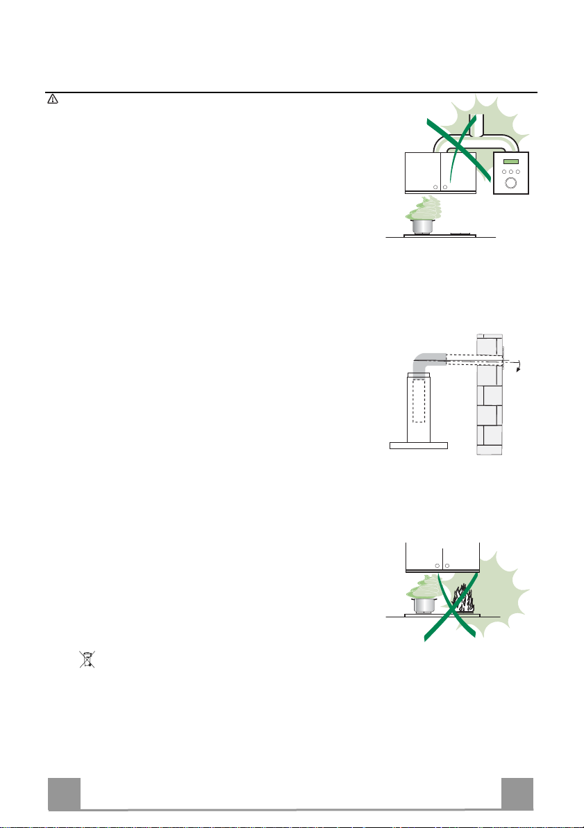
RECOMMENDATIONS AND SUGGESTIONS
The Instructions for Use apply to several versions of this appliance. Accordingly, you may fi nd
descriptions of individual features that do not apply to your specific appliance.
INSTALLATION
• The manufacturer will not be held liable for any damages resulti ng from incorrect or improper
installation.
• The minimum safety distance between the cooker top and the extractor hood is 650 mm (some
models can be installed at a lower height, please refer to the paragraphs on working dimensions
and installation).
• Check that the mains voltage corresponds to that indicated on the rating plate fixed to the inside of
the hood.
• For Class I appliances, check that the domestic power supply guarantees adequate earthing.
Connect the extractor to the exhaust flue through a pipe of minimum diameter 120 mm. The route
of the flue must be as short as possible.
• Do not connect the extractor hood to exhaust ducts carrying combustion fumes (boilers, fireplaces,
etc.).
• If the extractor is used in conjunction with non-electrical appliances (e.g. gas burning appliances), a
sufficient degree of aeration must be guarant eed i n the r oom in o rde r to p reve nt the b ackflow of
exhaust gas. The kitchen must have an opening communicating directly with the open air in order
to guarantee the entry of clean air. When the cooker hood is used in conjunction with appliances
supplied with energy other than electric, the negative pressure in the room must not exceed 0,04
mbar to prevent fumes being drawn back into the room by the cooker hood.
• In the event of damage t o the power cable, it must be replaced by the manufacturer or by the
technical service department, in order to prevent any risks.
“WARNING: Failure to install the screws or fixing device in accordance with these instructions may
result in electrical hazards.”
USE
• The extractor hood has been designed exclusively for domestic use to eliminate kitchen smells.
• Never use the hood for purposes other than for which it has been designed.
• Never leave high naked flames under the hood when it is in operation.
• Adjust the flame intensity to direct it onto the bottom of the pan only, making sure that it does not
engulf the sides.
• Deep fat fryers must be continuously monitored during use: overheated oil can burst into flames.
• Do not flambè under the range hood; risk of fire
• This appliance is not intended for use by persons (including children) with reduced physical, sensory or mental capabilities, or lack of experience and knowledge, unless they have been given supervision or instruction concerning use of the appliance by a person responsible for their safety.
• Children should be supervised to ensure that they do not play with the appliance.
• “WARNING: Accessible parts may become hot when used with cooking appliances.”.
MAINTENANCE
• Switch off or unplug the applian ce from the mains supply b efore carrying out any mai ntenance
work.
• Clean and/or replace the Filters after the specified time period (Fire hazard).
• Clean the hood using a damp cloth and a neutral liquid detergent.
The symbol on the product or on its packaging indicates that this product may not be treated as household waste. Instead it
shall be handed over to the applicable collection point for the recycling of electrical and electronic equipment. By ensuring this product
is disposed of correctly, you will help prevent potential negative consequences for the environment and human health, which could
otherwise be caused by inappropriate waste handling of this product. For more detailed information about recycling of this product,
please contact your local city office, your household waste disposal service or the shop where you purchased the product.
EN
3
3
Page 4
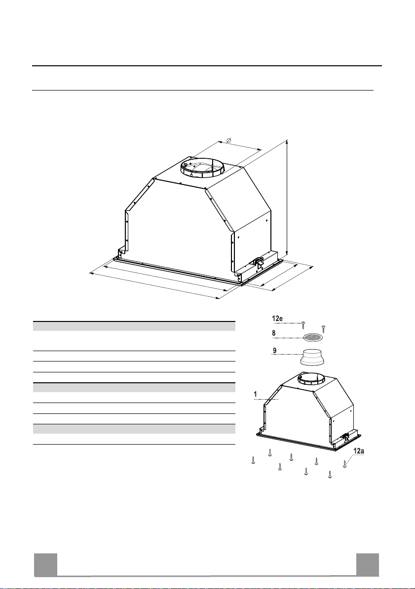
CHARACTERISTICS
Dimensions
150
323
498-678
524-700
Components
Ref. Q.ty Product Components
1 1 Hood Body, complete with :Controls, Light, Blower,
8 1 Directioned grid
9 1 Reducer Flange ø 150-120 mm
Ref. Q.ty Installation Components
12a 8 Screws
12e 2 Screws 2,9 x 9,5
Filters
Q.ty Documentation
1 Instruction Manual
EN
258
288
4
4
Page 5

INSTALLATION
Fitting the Hood canopy
BEFORE FITTING THE HOOD TO THE WALL UNIT, PROCEED AS FOLLOWS:
• Open the Panel by pulling it.
• Remove grease filters.
• Disconnect the wires to the Commands at the connectors.
• Remove the frame by unfastening the 4 screws (2
on the right and 2 on the left).
• The Hood can be installed directly on the underside of the
wall unit (Minimum 650 mm from the Cooker Hob).
• Create an opening in the bottom of the wall unit, as shown.
• Fasten using the 8 screws 12a provided.
• Screw the Frame back into place using the 4 screws removed
as described above, re-connect the wires to the Commands,
replace the metal grease filter and close the Panel.
13
500 - 680
260
EN
5
5
Page 6

Connections
DUCTED VERSION AIR EXHAUST SYSTEM
When installing the ducted version, connect the hood to
the chimney using either a flexible or rigid pipe ø 150
or 120 mm, the choice of which is left to the installer.
• To install a ø 120 mm air exhaust connection, insert
the reducer flange 9 on the hood body outlet.
• Fix the pipe in position using sufficient pipe clamps
(not supplied).
• Remove possible charcoal filters.
ø 150
ø 120
9
RECIRCULATION VERSION AIR OUTLET
• Cut a hole ø 125 mm in any shelf that may be positioned over the hood.
• Insert the reducer flange 9 on the hood body outlet.
• Connect the flange to the outlet on the shelf over the
hood by using a flexible or rigid pipe ø120 mm.
• Fix the pipe in position using sufficient pipe clamps
(not supplied).
• Fix the air outlet grid 8 on the recirculation air outlet
by using the 2 screws 12e (2,9 x 9,5) provided.
• Ensure that the activated charcoal filters have been
inserted.
ø 125
12e
8
9
ELECTRICAL CONNECTION
• Connect the hood to the mains through a two-pole switch having a contact gap of at least 3
mm..
EN
6
6
Page 7

USE
L1 L2 L3 L4
L T1 T2 T3 T4
Control panel
Button Function Led
L Turns the lighting system on and off. -
Press and hold for approx. 2 seconds to turn the
lighting system on and off at reduced intensity.
T1 Turn the suction motor on and off at speed one. On.
Press and hold the button for approximately 2
seconds, with all the loads turned off (Motor and
Lights), to reset the Filters and turn off the Leds that
are lit.
T2 Turn the suction motor on at speed two. On.
Press and hold for approximately 5 seconds, with all
the loads turned off (Motor and Lights), to
enable/disable the Remote control.
T3 Turn the suction motor on at speed three. On.
Press and hold the button for 2 seconds to activate
intensive speed. This speed is timed to run for 10
minutes. At the end of this time the system will
automatically return to the speed set before.
T4 Press and hold the button for approximately 2
seconds to activate automatic shutdown with a 30'
delay (Motor+Lights).
Press and hold for approximately 5 seconds to
enable/disable the Activated Charcoal Filter alarm.
-
After 100 working hours all the
LEDs (L1-L2-L3-L4) will light up
and remain lit to indicate saturation
of the metal grease filters.
After 200 working hours all the
LEDs (L1-L2-L3-L4) will light up
and start to flash to indicate
saturation of the activated charcoal
filters.
2 flashes, Remote control Enabled.
1 flash, Remote control Disabled.
On.
2 Flashes of the Leds (L1-L2-L3)
Filter Alarm Enabled.
1 Flash of the Leds (L1-L2-L3)
Filter Alarm Disabled.
EN
7
7
Page 8

MAINTENANCE
Opening Panel
• Open the Panel by pulling it.
• Clean the outside with a damp cloth and neutral detergent.
• Clean the inside using a damp cloth and neutral detergent; do
not use wet cloths or sponges, or jets of water; do not use
abrasive substances.
Metal grease filters
These can also be washed in the dishwasher, and need to be
cleaned when all the command LEDs light up in a continuous
manner or at least once every 2 months use, or more frequently if
use is particularly intensive.
Resetting the alarm signal
• Press button T1 (see the paragraph on Use).
Cleaning the Filters
• Pull the Comfort Panels to open them.
• Remove the Filters one at a time, pushing them towards the
back of the unit and at the same time pulling downward.
• Wash the Filters without bending them, and leave them to dry
completely before replacing.
• Replace, taking care to ensure that the handle faces forwards
• Close the comfort panels.
EN
8
8
Page 9

Activated Charcoal Filter (Recirculation Version)
• This cannot be washed or regenerated, and must be changed when all the command LEDs
start to flash, or at least once every 4 months.
Activating the alarm signal
• In Recirculation Version Hoods, the Filter Saturation Alarm must be activated on installation or at
a later date.
• Press and hold the Delay button (T4) on the keypad for 5 seconds and the following will be displayed:
• Leds (L1-L2-L3) flash twice – Activated Charcoal Filter saturation alarm ACTIVATED.
• Leds (L1-L2-L3) flash once – Activated Charcoal Filter saturation alarm DEACTI
VATED.
CHANGING THE ACTIVATED CHARCOAL FILTER
Resetting the alarm signal
• Press button T1 (see the paragraph on Use).
Changing the Filter
• Pull the Comfort Panels to open them.
• Remove the Metal grease filters.
• Remove the saturated Activated Charcoal Fil ters, as indicated (A).
• Fit the new Filters, as indicated ( B).
• Replace the Metal grease fil ters.
• Close the comfort panel.s
A
B
Lighting
LIGHT REPLACEMENT
20 W halogen light.
• Extract the lamp from the lamp holder by pulling gently.
• Replace with another of the same type, making sure that the
two pins are properly inserted in the lamp holder socket holes.
EN
9
9
Page 10

Page 11

Page 12

991.0264.134_ver2
 Loading...