

Page 1
Instructions Manual
SHB450X – SHB600X – SHB900X
Page 2

INDEX
RECOMMENDATIONS AND SUGGESTIONS.....................................................................................................................3
CHARACTERISTICS.............................................................................................................................................................4
INSTALLATION...................................................................................................................................................................... 5
USE........................................................................................................................................................................................8
MAINTENANCE.....................................................................................................................................................................9
EN
2
2
Page 3
2°
RECOMMENDATIONS AND SUGGESTIONS
The Instructions for Use apply to several versions of this appliance. Accordingly, you may fi nd
descriptions of individual features that do not apply to your specific appliance.
INSTALLATION
• The manufacturer will not be held liable for any damages resulti ng from incorrect or improper
installation.
• The minimum safety distance between the cooker top and the extractor hood is 650 mm (some
models can be installed at a lower height, please refer to the paragraphs on working dimensions
and installation).
• Check that the mains voltage corresponds to that indicated on the rating plate fixed to the inside of
the hood.
• For Class I appliances, check that the domestic power supply guarantees adequate earthing.
Connect the extractor to the exhaust flue through a pipe of minimum diameter 120 mm. The route
of the flue must be as short as possible.
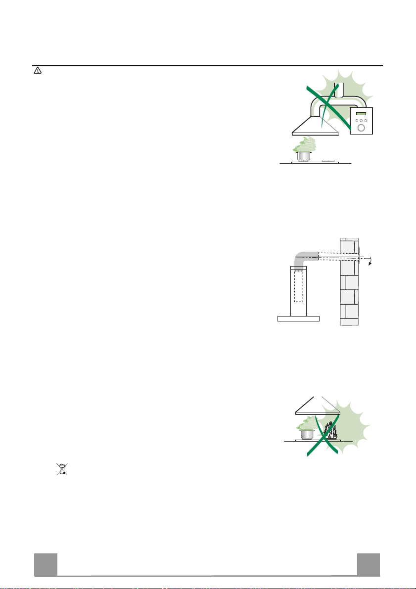
• Do not connect the extractor hood to exhaust ducts carrying combustion fumes (boilers, fireplaces,
etc.).
• If the extractor is used in conjunction with non-electrical appliances (e.g. gas burning appliances), a
sufficient degree of aeration must be guarant eed i n the r oom in o rde r to p reve nt the b ackflow of
exhaust gas. The kitchen must have an opening communicating directly with the open air in order
to guarantee the entry of clean air. When the cooker hood is used in conjunction with appliances
supplied with energy other than electric, the negative pressure in the room must not exceed 0,04
mbar to prevent fumes being drawn back into the room by the cooker hood.
• In the event of damage t o the power cable, it must be replaced by the manufacturer or by the
technical service department, in order to prevent any risks.
“WARNING: Failure to install the screws or fixing device in accordance with these instructions may
result in electrical hazards.”
USE
• The extractor hood has been designed exclusively for domestic use to eliminate kitchen smells.
• Never use the hood for purposes other than for which it has been designed.
• Never leave high naked flames under the hood when it is in operation.
• Adjust the flame intensity to direct it onto the bottom of the pan only, making sure that it does not
engulf the sides.
• Deep fat fryers must be continuously monitored during use: overheated oil can burst into flames.
• Do not flambè under the range hood; risk of fire
• This appliance is not intended for use by persons (including children) with reduced physical, sensory or mental capabilities, or lack of experience and knowledge, unless they have been given supervision or instruction concerning use of the appliance by a person responsible for their safety.
• Children should be supervised to ensure that they do not play with the appliance.
• “WARNING: Accessible parts may become hot when used with cooking appliances.”.
MAINTENANCE
• Switch off or unplug the applian ce from the mains supply b efore carrying out any mai ntenance
work.
• Clean and/or replace the Filters after the specified time period (Fire hazard).
• Clean the hood using a damp cloth and a neutral liquid detergent.
The symbol on the product or on its packaging indicates that this product may not be treated as household waste. Instead it
shall be handed over to the applicable collection point for the recycling of electrical and electronic equipment. By ensuring this product
is disposed of correctly, you will help prevent potential negative consequences for the environment and human health, which could
otherwise be caused by inappropriate waste handling of this product. For more detailed information about recycling of this product,
please contact your local city office, your household waste disposal service or the shop where you purchased the product.
EN
3
3
Page 4
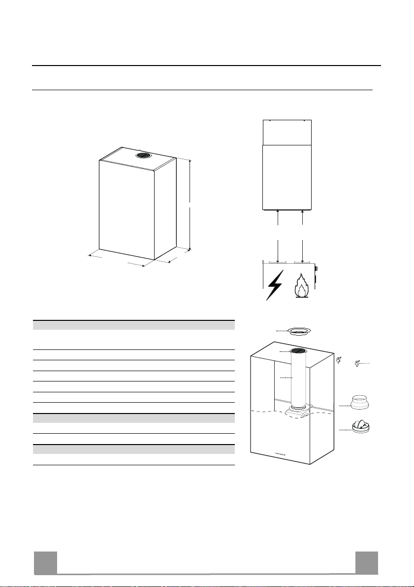
CHARACTERISTICS
Dimensions
890
Min.
550mm
Min.
550mm
448 - 598 - 898
420
Components
Ref. Q.ty Product components
1 1 Hood Body complete with: Controls, Light, Suction Unit,
7 1 PVC Pipe (fitted)
8 1 Inclinable grid (fitted)
9 1 Reduction flange ø 150-120 mm
10 1 Metal cover
10a 1 Dumper
Ref. Q.ty Assembly components
11a 2 SB 12/10 Plugs
Q.ty Documents
1 Instruction Manual
Filters, Lower Duct
10
8
11a
7
9
10a
EN
4
4
Page 5

INSTALLATION
Boring the wall
If you want to use the hood in suction version with the air outlet at the back of the hood, mak e
sure to follow the indications given below in the drawing for a correct boring operation of the air
outlet opening.
Type Hood 45 60 90
X 180 240 390
X
X
11a
540 300
250
808
Rear air outlet
zone
550 mm min
When installing the hood in recycling version it has to be taken into consideration that space remaining between the hood and the upper limit (ceiling or self) is at least 8-10 cm.
On the wall, trace:
• a vertical line up to the ceiling or top limit, at the centre of the area where you intend to fit
the hood;
• a horizontal line at: 550 mm min. above the cooking hob;
• As shown, mark a reference point at 808 mm above the horizontal reference line, and at X
mm (X= see table in figure) to the right of the vertical reference line.
• Repeat this operation on the opposite side, checking levelling.
• Drill the points marked using a ø 12 mm bit
• Insert plugs with screws and brackets 11a in the holes then tighten them.
EN
5
5
Page 6

Vr
11a
10
10
10a
10a
9
ø 150
ø 120
Hood body assembly
• Adjust the two screws Vr of brackets 11a, by just placing them
in position.
• Hook the hood body to the two brackets 11a.
• Pull the Comfort Panel to open it, remove the filters one by
one, push them towards the rear part of the unit and pull
downwards at the same time .
• From inside the hood body, tighten the screws Vr to level the
body.
Connection
AIR OUTLET IN A DUCTING HOOD VERSION
When installing the hood in ducting version, basing on the installer’s choice, a rigid or a flexible pipe with a ø 150 or 120 mm
is used in order to connect the hood to the air outlet piping. The
pipe connection can be made on the upper part or on the rear side
of the hood.
Before connecting the hood to the air outlet ducting remove the
lateral air outlet grid 8 and the plastic tube 7. The adapting flange
9 has to be removed only in case the connecting diameter is 150.
To install the dumper 10a on the hood body outlet.
REAR AIR OUTLET
• When drilling the air outlet hole in the wall proceed in accordance with the scheme in the part concerning the wall drilling.
• Use a pair of tongs when breaking the rear air outlet hole in the
wall.
• In case the connection is made by using a ø 120 mm pipe insert
the reduction flange 9 on the Dumper 10a.
• Fix the pipe with an adequate quantity of pipe clamps. This
material is not supplied together with the hood.
• Remove the charcoal filter if present.
• Fix the metal cover 10 to the upper air outlet hole of the hood
by using the screws supplied.
UPPER AIR OUTLET
• In case the connection is made by using a ø 120 mm pipe insert
the reduction flange 9 on the Dumper 10a.
• Use a pair of tongs when removing the central part of the metal
cover 10. Fix the cover to the air outlet hole of the hood by using the screws supplied.
• Fix the pipe with an adequate quantity of pipe clamps. This
material is not supplied together with the hood.
• Remove the charcoal filter if present.
EN
6
6
Page 7

8
7
AIR OUTLET IN A RECYCLING HOOD VERSION
• In case the components requested for the recycling functioning
have been removed earlier these have to be positioned again.
• Put the plastic tube onto the flange 7.
• Place the air outlet grid 8 on the air outlet. Make sure that the
position of the grid is correct.
• Make sure that charcoal filters have been placed inside the
hood.
ELECTRICAL CONNECTION
• Connect the hood to the mains through a two-pole switch having a contact gap of at least 3 mm.
• Remove the grease filters (see paragraph Maintenance) being
sure that the connector of the feeding cable is correctly inserted
in the socket placed on the side of the fan.
EN
7
7
Page 8
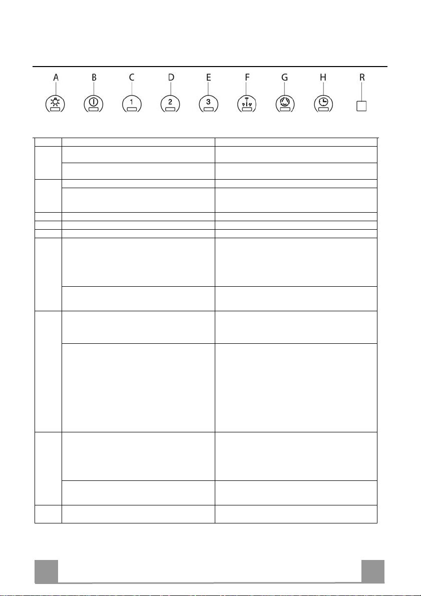
USE
Button Function Led
A Turns the lighting system on and off at maximum
intensity.
Turns the lighting system on and off in Courtesy Light
mode.
B Turns the Motor off.
Press and hold for approximately 5 seconds to Lock /
Unlock the Keyboard, for example in order to clean the
surface.
C Turns the Motor on at Speed one. On/Off
D Turns the Motor on at Speed two. On/Off
E Turns the Motor on at Speed three. On/Off
F Activates/Deactivates intensive speed from any o ther
speed, including motor off. This speed is set to operate
for 10 minutes, after which the system returns to the
speed that was set before. Suitable to deal with
maximum levels of cooking fumes. Can also be
deactivated by pressing button B.
Press and hold the button for approximately 5 seconds,
with all the loads turned off (Motor and Lights), to turn
the Activated Charcoal Filter alarm on/off.
G 24H function
Turns the motor On/Off at speed one and allows
recirculation for 10 minutes every hour. It cannot be
activated if the Intensive or Delay functions are in use.
When the filters alarm is t riggered, the alarm can be
reset by pressing and holding this button for
approximately 5 seconds.
These indications are only visible when the motor is
turned off.
H Delay function
Activates/Deactivates automatic switch-off with a 30’
delay. Suitable to complete elimination of residual
odours. Can be activated from any position. It cannot
be activated if the Intensive or 24H functions are in
use.
Press and hold the button for approximately 5 seconds,
with all the loads turned off (Motor and Lights), to turn
the Remote control on/off.
R Remote control receiv er.
Control panel
On/Off
On/Off
The buttons turn light up one at a time in cycle.
Flashes once a second.
Button B (Flashes twice)-Alarm Activated.
Button B (Flashes once)-Alarm Deactivated.
On/Off
B flashes three times.
When the procedure terminates, the indication shown
previously turns off:
Button G flashes, indicating the need to wash the metal
grease filters. The alarm is triggered after the Hood has
been in operation for 100 working hours.
Button G flashes, indicating the need to change the
activated charcoal filters, and also to wash the metal grease
filters. The alarm is triggered after the Hood has been in
operation for 200 working hours.
On/Off
Button B (Flashes twice)-Remote control Activated.
Button B (Flashes once)-Remote control Deactivated.
EN
8
8
Page 9

MAINTENANCE
REMOTE CONTROL (OPTIONAL)
The appliance can be controlled using a remote control powered
by a 1.5 V carbon-zinc alkaline batteries of the standard LR03AAA type (not included).
• Do not place the remote control near to heat sources.
• Used batteries must be disposed of in the proper manner.
Cleaning the Comfort Panels
• Pull the Comfort Panel to open it.
• Disconnect the panel from the hood canopy by sliding the fixing pin lever.
• The comfort panel must never be washed in a dishwasher.
• Clean the outside by using a damp cloth and neutral liquid detergent.
• Clean the inside as well by using a damp cloth and neutral detergent; do not use wet cloths or sponges, or jets of water; do
not use abrasive substances.
• When the above operation has been completed, hook the panel
back to the hood canopy and close it by turning the knob in the
opposite direction.
EN
9
9
Page 10

Metal grease filters
They can be washed in the dishwasher, and need to be cleaned
whenever Button G flashes or at least once every 2 months use,
or more frequently if use is particularly intensive.
Resetting the alarm signal
• Turn the Lights and the Suction motor off, then disable the 24h
function, if enabled.
• Press button G and hold for approximately 5 seconds (See
paragraph on Use).
Cleaning the filters
• Pull the comfort panels to open them.
• Remove the filters one by one pushing them towards the back
side of the hood unit and simultaneously pulling downwards.
• Any kind of bending of the filters has to be avoided when
washing them. Before fitting them again into the hood make
sure that they are completely dry. (The colour of the filter surface may change throughout the time but this has no influence
to the filter efficiency).
• When fitting the filters into the hood pay attention that they are
mounted in correct position the handle facing outwards.
• Close the comfort panel.
.
EN
1
10
Page 11

Activated Charcoal Filter (Recirculation Version)
This cannot be washed or regenerated, and must be changed when G starts to flash, or at least
once every 4 months. The Alarm signal, if it has been activated, only appears when the Suction
motor is turned on.
Activating the alarm signal
• In Recirculation Version Hoods, the Filter Saturation Alarm must be activated on installation or at a later date.
• Turn the Lights and the Suction Motor off.
• Press F and hold for approximately 5 seconds:
• Button B flashes twice -- A.C. Filter saturation alarm ACTIVATED
• Button B flashes once -- A.C. Filter saturation alarm DEACTIVATED
CHANGING THE ACTIVATED CHARCOAL FILTER
Resetting the alarm signal
• Turn the Lights and the Suction Motor off.
• Press button G and hold for approximately 5 seconds (See
paragraph on Use).
Changing the Filter
• Open the comfort panels pulling them downwards.
• Remove grease filters.
• Remove the saturated activated charcoal filters, as indicated
(A).
• Fit the new filters, as indicated (B).
• Replace the metal grease filters.
• Close the comfort panels.
A
B
Lighting
LIGHT REPLACEMENT
20 W halogen light.
• Remove the 2 screws fixing the Lighting support, and pull it
out of from the Hood.
• Extract the lamp from the Support.
• Replace with another of the same type, making sure that the
two pins are properly inserted in the lamp holder socket holes.
• Refit the Support, fixing it in place with the two screws removed as above.
EN
1
11
Page 12
436006041_ver2
 Loading...