


SGR
2
0S
Betriebsanleitung
Operating Instructions
Istruzioni per l’uso
9.696.037

1
SGR20S
Table of Contents
& ENGLISH
Contents Page
1 Table of contents 1
2 Introduction 2
3 Before Starting
Guide to these Operating Instructions 3
Intended Use 3
Set -Up and Function 4
Safety instructions 5
Installation 5
Start –Up 6
4 Basic Functions
Programming Aids 7
Configuration of the device 8
Configuration of the printer 8
Data Input 9
Activation of the printing data 10
Special functions 11
Operation 12
5 Troubleshooting and Maintenance
Troubleshooting Chart 13
Maintenance Chart 15
Parts Service 15
Parts Required for Maintenance and Wear 16
Replacement parts 17
Part numbers 18
Maintenance Information
Replacing ink ribbon 19
Replacing PTFE strip on guide rail 20
Replacing PTFE strip for heating die 21
Replacing pressure roller 22
Calibration 23
Stand by 24
6 Technical Data
Circuit and Wiring Diagram 230 / 115 V 25
Specifications 26
Declaration of Conformity 27
9.696.037
GB
1
ENGLISH
2
SGR20S
Operating Instructions
Introduction
First we would like to thank you for purchasing the SGR20S sealing machine.
These instructions include information on the machine, its function and operation.
! Please read these operating instructions thoroughly before using the machine so that you will
be familiar with the capabilities of the machine and can utilise its features to the optimum.
FAlways keep these instructions in the vicinity of the machine.
Important note:
This device is a packaging machine for the processing of thermoplastic films and composite films
according to the thermal – bonding or sealing process.
In this respect , please pay attention to the “Intended use” chapter in the operating instructions.
According to the intended use , the CE symbol was affixed on the basis
of the EU Directives named below:
89/336/EEC, 98/37/EEC
and 73/23EEC amended by 93/68EEC.
The 93/42EEC Directive is not applicable to bonding and sealing devices.
The limit values stipulated in IEC 60601 – 1 cannot be applied in case of the electrical repetition tests.
The manufacturer will not assume any liability for damage caused by tests according to standards which
are not listed in the declaration of conformity .
Note
Since we continuously improve our products we reserve all
rights to modify these operating instructions and the
functions described therein.
We make all possible efforts to keep these instructions free of
errors and complete. If you note any errors or unclear points
please advise us.
GB
2
9.696.037

ENGLISH
3
SGR20S
Before Starting
Guide to these Operating Instructions
Before Starting
Basic Functions
Troubleshooting
and
Maintenance
Technical Data
This chapter contains information on the functions of the machine and
instructions for handling and installation.
BE SURE TO READ!
Adjustment and operation of the machine are explained here.
Instructions for finding causes of malfunctions and eliminating them.
This chapter includes information on the required maintenance, parts
subject to wear and replacement parts.
Shows the interrelationship between various item numbers, the circuit
and diagram plans and machine specifications.
Intended Use
The SGR20S machine is intended for commercial and industrial applications and should
be used only for the intended purpose.
The SGR20S machine is a sealing machine for sealing sterilization packages
consisting of paper, paper laminate foil or Tyvek foil.
! It is not suitable for sealing pure polyethylene foils, soft PVC foils, hard PVC foils,
polyamide foils or polypropylene foils.
The machine capacity depends on the characteristics of the sealing material used.
9.696.037
GB
3
ENGLISH
3
SGR20S
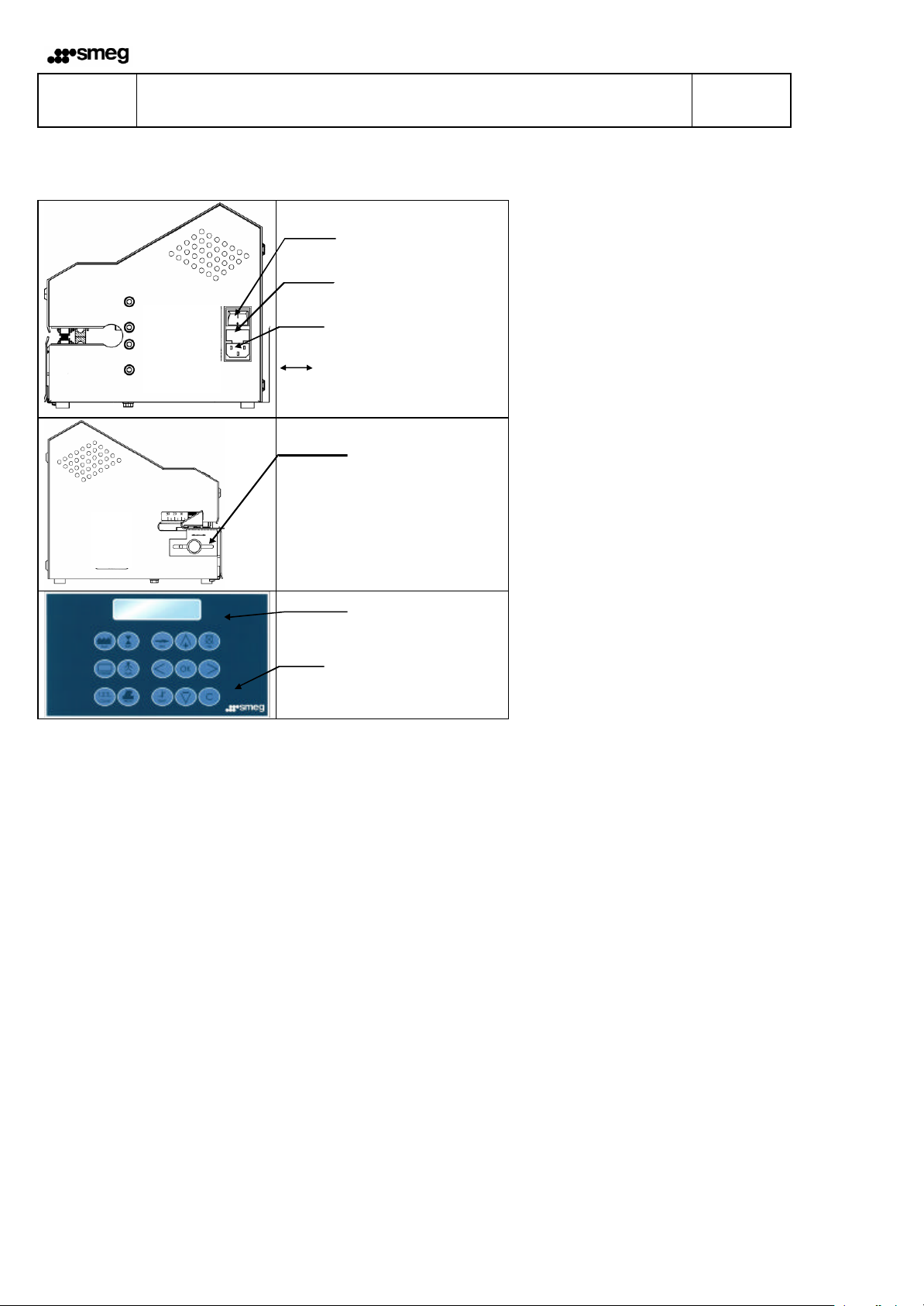
Set-Up and Function
Before Starting
Power switch
Power fuse
Power connection
Adjustable for the user manual
Peel edge adjustment
5 - 30 mm
Display
Input and
function keys
Sealing and Printing Operation Sequence
1. After inserting the sterilization package switch on transport.
2. The sterilization package is then transported and the area of the sealing seam is heated to the sealing
temperature set on the upper and lower heating dies.
3. The hot seam is pressed together by the sealing roller sealing it.
4. The printing operation is activated and the activated print data is printed onto the sealed package.
5. The finished sterilization package is transported to the discharge side.
6. If more packages to be sealed are not fed in the transport mechanism shuts off after approx. 30 s.
GB
4
9.696.037
ENGLISH
3
•
Œ
SGR20S
Before Starting
General safety instructions
The device must not be installed or operated by persons under
14 years of age.
The device must not be operated unattendedly.
I
Turn of the device or disconnect the power cord when it is not in use.
The device should only be cleaned with a dry or slightly damp cloth.
Warning! Never clean the device wet!
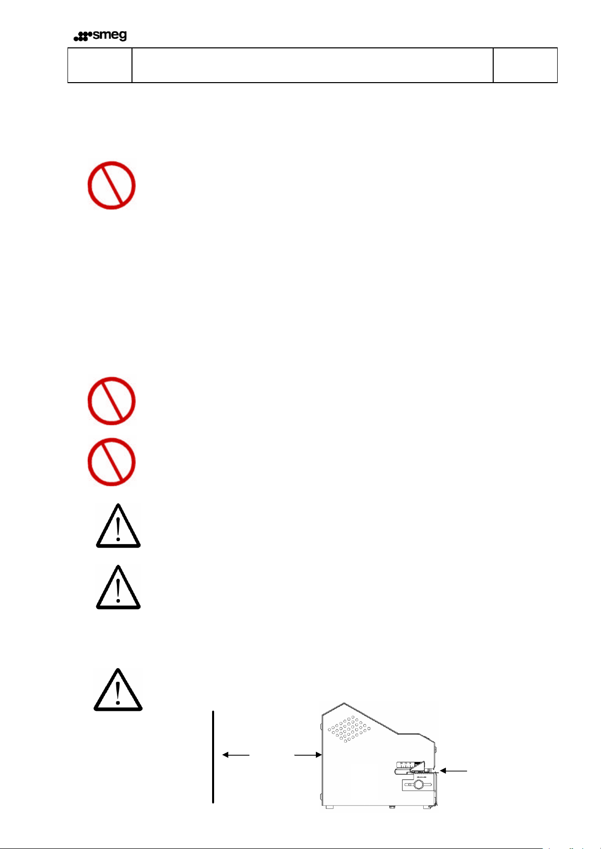
Installation
Do not install or operate the machine in explosion hazard areas.
I
I
Use only power sockets with protective ground.
Set up the machine only in dry areas.
Heavy dust, vapour, dripping or spraying water have a negative effect
on the machine functions.
Always ensure that the operating power corresponds to the specifications on the
machine rating plate.
F Please choose a socket where the line power is stable.
Please do not transport device on the peel edge setting! Œ
Leave a gap of 200 mm between the device and the wall. •
9.696.037
200 mm
5
GB
3
956579
Nominal temp 140°C
SGR20S
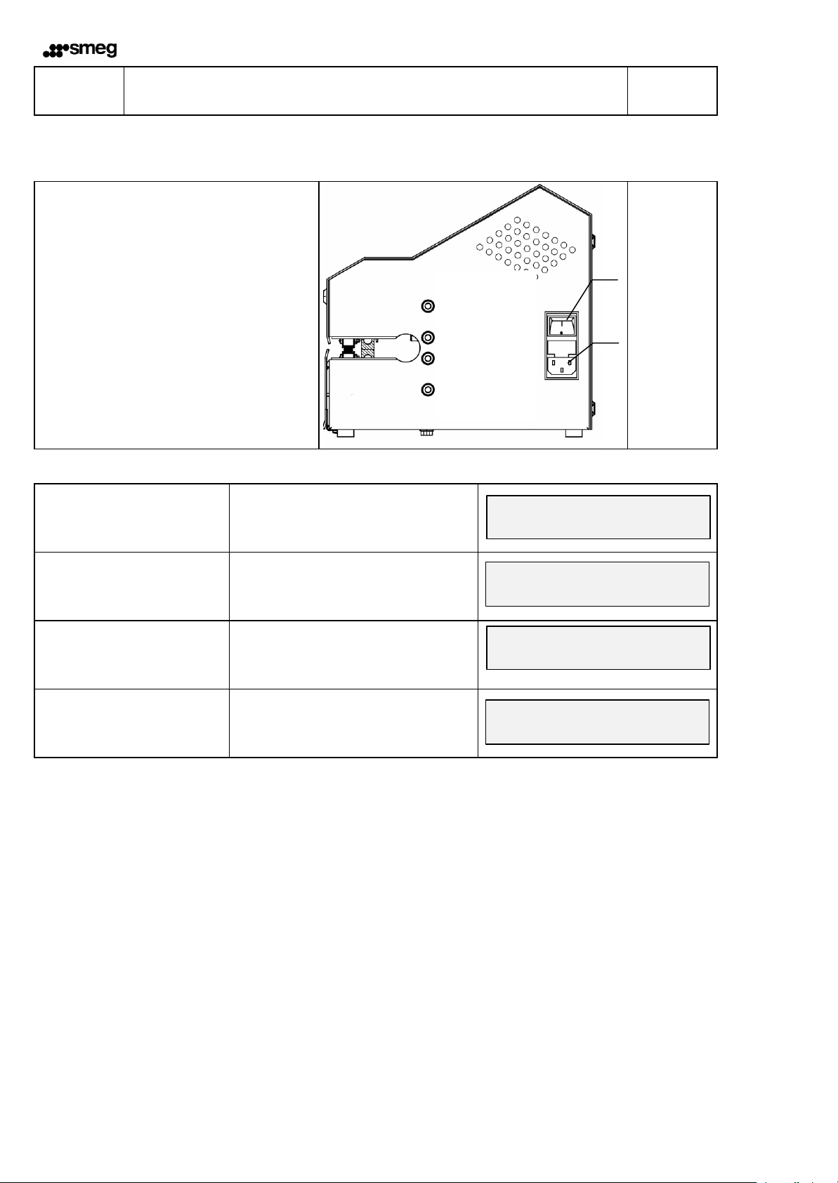
Start-Up
ENGLISH
Before Starting
l Plug power cable into power socket
on machine
l Insert plug into wall socket
l Switch on machine
with power switch
FUNCTION DISPLAY
Machine switched on
Self-test runs for approx. 30 s
Display for approx. 5 seconds:
V2.8 = Program version
956579 = Machine number
Display of
date, time
Actual temperature.
Setemperature
After 5 minutes is the
set temperature reached
Machine is ready for operation
Please wait
Control 800 V2.8
17-02-00 14:30 025°C
17-02-00 14:35 140°C
Power switch
Switch
conection
6
GB
9.696.037
ENGLISH
4
SGR20S
Basic Functions
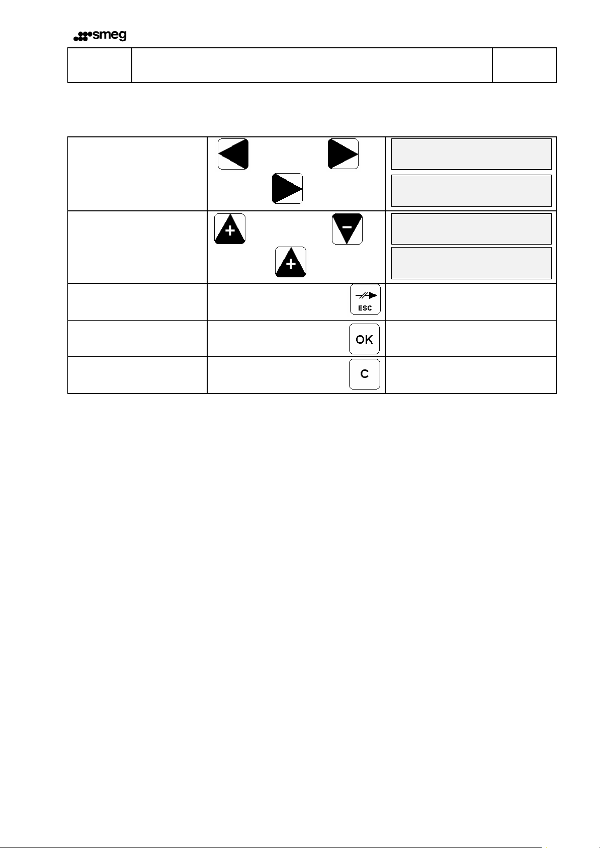
Programming Aids
FUNCTION KEYS DISPLAY
INPUT AIDS
Cursor control
Press - cursor right - key once
INPUT AIDS
Changing numbers and
letters
Press key - position +1 - once
INPUT AIDS
Return to previous menu
point without activating entry
INPUT AIDS
Activate input
Cursor Cursor
1x
left right
Position +1Position -1
1x
100°C
5Cursor flashes at 1st digit
100°C
5Cursor flashes at 2nd digit
100°C
st
51
digit is number 1
200°C
51st digit is number 2
INPUT AIDS
Space at selected point
Set piece counter to 0
9.696.037
GB
7
ENGLISH
YES
00 0
-
99mm
0 0
-
5
4
GB
C
SGR20S
Basic Functions
Configuration
FUNCTION KEYS DISPLAY
CONTRAST SETTING
DATA INPUT
Selection: Language, symbols,
temperature unit
Language:
DE, GB, FR, ES, IT, FI, SE, PL
Symbols: yes/no
Temperature unit : C / F
è
è
Language selection
yes / no
Celsius / Fahrenheit
Contrast é
Contrast ê
display - contrast
set language
pictogramm NO
temperature unit
Printer Set-Up
FUNCTION KEYS DISPLAY
PRINTER SET UP
Start printing
0 - 99 mm
Character width
0 - 5
è
Yes / No
Input
Start printing
Input
Character width
Input
printer set up
distance
character width
8
GB
9.696.037

ENGLISH
4
DD-MM
-
YYYY
17-03-2000 1
1234567890
0987654321
123
4567
SMEG
17-02-2000 08:57
175°C
SGR20S
Basic Functions
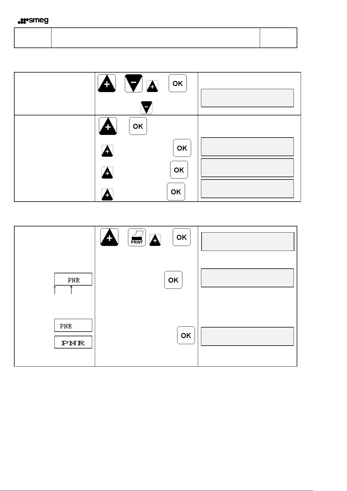
Data Input
FUNCTION KEYS DISPLAY
TEMPERATURE
Nominal temperature input
80 - 220 °C / 176 - 428 ° F
DATA INPUT
Date and time
Input of 6 different date
formats
1 dd-mm-yyyy 2 mm-dd-yyyy
3 yyyy-mm 4 mm-yyyy
5 yyyy 6 yyyy-mm-dd
DATA INPUT
Expiration date
Enter 3 differnt expiration
dates,
ex works: 1= Date + 1 Month
2= Date + 3 Month
3= Date + 6 Month
DATA INPUT
Charge number
10-digit, alphanumerical
DATA INPUT
Personnel number
20-digit, alphanumerical
DATA INPUT
Piece counter
7-digit, numerical
DATA INPUT
Text
20-digit, alphanumerical
Input
Temperature
è ê
1,2,3,4,5,6
Input
ê
1,2,3
date, time
Input
Expiration date
Input
Charge number
Input
Personnel number
Input
Piece Counter
Input
Text
nominal temp.
for mat date & time
DD-MM-YY hh:mm
DD-MM-YYYY
piece counter
text input
9.696.037
GB
9

ENGLISH
ays print in the same
4
17-02-2000
17-03-200
0 1
1234567890
0987654321
12345
SMEG
17-03-2000
17-02-2000
17-02-2000
SGR20S
Basic Functions
Data Activa tion / Deactivation
FUNCTION
The print sequence is
predefined, this means the
individual information like
Sterlization date
Expiry date
Charge number
Personnel number
Piece counter
Text
get alw
sequence
FUNCTION KEYS DISPLAY
PRINT
Sterilization date
PRINT
Expiration date
Selection of 3 different
expiration dates
PRINT
Charge number
PRINT
Personnel number
PRINT
Piece counter
PRINT
Text
Print: Sterlization date, Expiry date, Personnel number
Print: Sterlization date, Personnel number
Print Do not print
Miller
Print Do not print
ê
1,2,3
Print Do not print
Print Do not print
Print Do not print
Print Do not print
piece counter
text input
Miller
10
GB
9.696.037

ENGLISH
1234567
000053 h 25 min
printer off
4
SGR20S
Basic Functions
Special functions
FUNCTION KEYS DISPLAY
PRINT
Printer OFF/ON
DISPLAYS
Absolute part counter
è
DISPLAYS
Operating time counter
è
17-02-2000 14:30 180°C
absolute p. counter
operating time
9.696.037
GB
11

ENGLISH
4
SGR20S
Basic Functions
Operation
Sealing Operation
l Adjust peeling edge width
After loosening the arrest the peeling edge can be adjusted infinitely between 5 mm and 30 mm
by moving the plate.
l Insert sterilization package
The drive is switched on automatically.
l Removed sealed sterilization package and allow to cool briefly.
F Check strength by tearing open seal.
If unsealed points are present increase the sealing temperature. If the paper discolors or the
foil peels off the temperature is too high.
Deter mine suitable sealing temperature with sealing tests.
GB
12
9.696.037

ENGLISH
5
SGR20S
Troubleshooting and Maintenance
Troubleshooting Chart
Malfunction Possible cause Remedy
Machine cannot be switched
on
No data on display
Machine does not heat up
No transport Motor sensor
Power connection
Power cable not plugged in
Power cable defective
Power fuse
Control board
Display board
Nominal temperature too low
Temperature limitation active
Temperature sensor
Heating cartridge
Control board
Front flap not closed
Front flap - sensor
Transport belt
Damaged
No transport
Motor
Control board
Check power connection, if
necessary connect to different
socket.
Replace power cable.
Replace power fuse
! If fuse blow s again always have
machine checked.
Replace control board
Replace display board
Increase nominal temperature
Reset temperature limiter
by pressing in pin
! If temperature limiter trips again
always have machine checked
Replace temperature sensor
Check heating cartridges, replace if
necessary
Replace control board
Replace light barrier
Close front flap
Replace front flap sensor
Replace transport belt
Check belt tension
Replace motor
Replace control board
9.696.037
GB
13

ENGLISH
5
SGR20S
Troubleshooting and Maintenance
Troubleshooting Chart
Malfunction Possible cause Remedy
Material feed not uniform or
loud running noise
Seal does not hold
Sealing seam distorted Pressure
Paper side of
package discolored
or side fold shrunk
No imprint or
imprint incomplete
Imprint too weak
Keyboard does not work Keyboard
Transport belt guide
Transport belt
Damaged
No transport
Motor
Temperature
too low
Pressure
too low
too high
Temperature
too high
Programming
Start of print not correctly adjusted
Ink ribbon
Printer head
Control board
Ink ribbon
Print head
Paper hold-down
Display board
Control board
Replace PTFE belt on guide die
Replace transport belt
Check belt tension
Replace motor
Increase temperature
Readjust pressure of sealing roller or
replace sealing roller
Loosen upper guide die and readjust
downward
Reduce temperature
Reprogram start of print
Ink ribbon not correctly installed
Replace ink ribbon
Replace print head
Replace control board
Replace ink ribbon.
Readjust print head.
Replace pressure spring for paper
hold-down
Check keyboard connector for good
contact.
Replace keyboard
Replace display board.
Replace control board
GB
14
9.696.037

ENGLISH
5
Check
Replace
Adjust
Measure
SGR20S
Troubleshooting and Maintenance
Maintenance Chart
As all technical equipment your equipment is also subject to technical wear.
In order to ensure that your machine is always ready for use it should be serviced at least
once annually by a trained technician.
Maintenance
chart
At least every
3 months
Depending on
use, at least
once annualy
Ink ribbon
PTFE strip
for guide
die
PTFE strip
for sealing
die
Pressure
roller
Parts Service
F Simply order parts by fax:
l Please copy the following pages according to the parts required.
Page 17: Parts required for maintenance and wear
Page 18: Replacement parts
l Enter machine number.
l Enter machine model
l Enter name, address, fax number and order number.
l Mark items required
l Enter quantity required.
l Sign order.
l Fax order.
Toothed
belt
No.: 123456
Type: SGR20S
Sealing die
interval
Sealing
temperature
between
sealing die
9.696.037
GB
15

To:
Fax
Order Nr ______________ Date: ________________
Machine Model ______________ Machine number _______________
þ
¨
¨
¨
¨
¨
¨
¨
¨
¨
¨
Ink ribbon
PTFE strip for sealing die
PTFE strib for upper guide rail
PTFE strib for lower guide rail
Pressure roller plastic
Toothhead belt drive 225 mm
Toothhead belt drive 355 mm
Toothhead belt, material transport
Heating cartridge
From:
Designation
Part No
6.813.104
6.105.125
6.105.139
6.105.138
2.230.008
6.271.004
6.271.002
6.271.008
6.536.032
qty
¨
¨
¨
¨
Signature __________
GB
16
9.696.037

To:
Fax
Order No ______________ Date: ______________
Machine model ______________ machine number _______________
þ
From:
Designation
Part No
qty
¨
¨
¨
¨
¨
¨
¨
¨
¨
¨
Print head
Control board 230V
Control board 115V
Display board
Gear motor 230V
Gear motor 115V
Light barrier
Temperature limit switch
Thermocouple
1.653.002
1.410.063
1.410.064
1.410.017
1.212.005
1.212.014
1.561.003
6.564.018
6.564.023
¨
¨
¨
¨
Signature ____________________
9.696.037
GB
17

5
6.105.139
2.301.027
SGR20S
ENGLISH
Troubleshooting and Maintenance
Part numbers
Heating die
upper guide rail
lower guide rail
6.105.285
6.564.023
6.536.032
6.564.018
2.301.027
2.651.186
6.181.011
2.301.027
6.105.139
2.301.027
GB
18
9.696.037

ENGLISH
5
H
SGR20S
Troubleshooting and Maintenance
Maintenance Information
Replacing ink ribbon
l Switch off machine
l Open front flap
l Press lever for ink ribbon holder Πdown with left hand.
l Press holder for rink ribbon cassette • to side and remove cassette.
l Insert new ink ribbon cassette.
Always ensure that the transport opening Ž in the cassette is attached to the transport shaft •.
l Press ink ribbon cassette toward rear until holder • catches .
l Close front flap
l Switch on machine and check printing function after reaching nominal temperature.
E•
Œ
•
Ž
9.696.037
GB
19

ENGLISH
5
Ž
SGR20S
Troubleshooting and Maintenance
Maintenance Information ! Please use only genuine replacement parts.
Replacing PTFE strip on guide rail
l Switch off machine and DISCONNET POWER PLUG !
l Open housing
l Remove mounting screws Πfor upper guide rail and remove guide rail or
l Remove mounting screws• for lower guide rail and remove guide rail
l Remove mounting screws Ž and detach PTFE strip
l Pull backing foil off of new PTFE strip and glue new PTFE strip on straight and without wrinkles
l Fasten PTFE strip with screws Ž
l Install guide rail
FWhen installing the upper guide rail before fastening, push the die down so that the interval between the screw head
and rail is 1 mm on both sides. This ensures the correct contact pressure for the guide rail.
l Close housing
Œ Œ Œ
• •
Ž
Distance between screw head and rail = 1 mm
PTFE strip
GB
20
9.696.037

ENGLISH
5
Œ • • ‘ ‘
SGR20S
Troubleshooting and Maintenance
Maintenance Information ! Please use only genuine replacement parts.
Replacing PTFE strip for upper and lower heating die
l Switch off machine and DISCONNET POWER PLUG !
l Open housing
l Remove mounting screws Πfor upper guide rail and remove guide rail.
l Remove pressure spring •
Œ
l Remove backing foil on new PTFE strip and glue newe PTFE strip on straight and without wrinkels
l Fasten PTFE strip with screw ‘
l Install heating die
l Insert spacer and fasten with mounting screws •
l Reconnect electrical connections to heating die
l Install pressure spring •
l Install guide rails.
Œ
l Disconnect electrical connections for heating die
l Unscrew mounting srew • and remove spacer
l Remove top or bottom heating die
l Unscrew mounting screw ‘ and detach PTFE
strip
FWhen installing the upper guide rail before fastening , push the die down so that the interval
between the srew head and rail is 1mm on both sides.
This ensures the correct contact pressure for the guide rail
l Close housing
9.696.037
Distance between screw head and rail = 1mm
GB
21

ENGLISH
5
SGR20S
Troubleshooting and Maintenance
Maintenance Information ! Please use only genuine replacement parts.
Replacing pressure roller
l Switch off machine and DISCONNET POWER PLUG !
l Open housing
l Remove mounting screws Πfor upper guide rail and remove guide rail.
l Loosen mounting screw Ž and pull pressure roller completely out of holder
l Detach snap ring • and remove pressure roller
l Install new pressure roller and fasten with snap ring •
l Position complete pressure roller in holder, center in relation to bottom roller and tighten mounting screw Ž
l Install guide rail
Œ Œ Œ
Ž
•
FWhen installing the upper guide rail before fastening, push the die down so that the interval between
the screw head and rail is 1 mm on both sides. This ensures the correct contact pressure for the guide rail.
l Close housing
Distance between screw head and rail = 1 mm
GB
22
9.696.037

ENGLISH
5
next key
GB
test print
distance 1 mm
distance 2
SGR20S
Troubleshooting and Maintenance
Calibration
After replacing the temperature sensor or heating elements it is necessary to calibrate the temperature. After replacing the
print head or "print start" light barrier it is necessary to calibrate the printer.After replacing the electronic unit it is necessary
to perform both adjustment operations.
FUNCTION KEYS DISPLAY
Switch off machine
All 3 keys together
Switch on machine
Self-test runs for approx. 30 s
Select language
Language:
German, English, French,
Spanish, Italian
SYSTEM CALIBRATION
TEMPERATURE
Measure temperature between
printing dies
PRINTER
1. Print test with
specimen > 150 mm
2. Measure distance 1 and 2
Bottom of specimen
Distance 1 Distance 2
+
+ +
Language selection
Temperature Printer
After reaching T=120 °C / 248 °F:
Enter measured temperature 1 after
waiting 120 sec.
Input
temperature 1
After reaching T=200 °C / 392 °F:
Enter measured temperature 2 after
waiting 120 sec.
Input
temperature 2
Confirm test printout
Input distance 1
Input distance 2
Please wait
Set language
system calibration
Time 1 Temperature 1
120 120°C
reading : °C
Time 2 Temperature 2
120 200°C
reading : °C
printer calibration
printer calibration
printer calibration
mm
Switch off machine
9.696.037
GB
23

ENGLISH
6
120 min
20 min
Yes
GB
SGR20S
Stand by function
Switch off machine
All 3 keys together
Switch on machine
Self-test runs for approx. 30 s
Select language
Language:
German, English, French,
Spanish, Italian
Press buttons in sequence
Enter time for switch over the
standby operation,
min 10 min
max 120 min
Stand by function
activate / deactivate
+ + +
Technical Data
+
Input
yes / no
Please wait
Set language
Stand by after
Stand by after
Activate Stand by
GB
24
9.696.037

ENGLISH
6
230V ~
− +
− +
SGR20S
Technical Data
Circuit and Wiring Diagram 230 V
Display board
Thermocouple
24V
Motor
Transport
M
1 2
4 3
Relais
Fan
Temperature limit switch
230V ~
Heating
Cardridge
115V 200W
1 2 3 4 5 6 7 8 9
2 1 1 3 5 4 4 6 8 7 7 9
OPB 704
OPB 704
OPB 704
Motor Printer Front flap
Circuit and Wiring Diagram 115 V
Display board
Thermocouple
Print head
115V ~
Motor
Transport
M
1 2
4 3
Main fuse 2 x 2 AT
Fan
115V ~
Relais
Temperature limit switch
24V
1 2 3 4 5 6 7 8 9
2 1 1 3 5 4 4 6 8 7 7 9
OPB 704
OPB 704
OPB 704
Motor Printer Front flap
9.696.037
Print head
Main fuse 2 x 5 AM
Heating
Cardridge
115V 200W
GB
25

6
ENGLISH
SGR20S
Technical Data
Specifications
Power connection [ V ] 230 / 115
Main fuse 230 V (115V) [ A ] 2 T ( 5 M )
Power consumption max [ W ] 500
Heat dissipation [ kJ/s] 0,1
Noise intensity [ dB/ A ] <70
Ambient temperature [ °C ] 5-25
Dimensions, length [ mm ]
width
height
Weight approx. [ kg ] 23
Processing speed [ m / min ] 10
Sealing temperature [ °C ] 80-220
Sealing temperature tolerance [+ - % ] 2
Sealing seam [ mm ] 12
Infinitely adjustable sealing edge [ mm ] 5-30
Sealing seam length [ mm ] unlimited
620
260
250
GB
26
9.696.037
 Loading...