

Page 1

30" (76.2 CM) AND 36" (91.4 CM)
IMPORTANT:
Sa
IMPOR
À conser
.
ELECTRIC INDUCTION COOKTOP
INSTALLATION INSTRUCTIONS
INSTRUCTIONS D’INSTALLATION DE
LA TABLE DE CUISSON ÉLECTRIQUE
À INDUCTION DE
30" (76,2 CM) ET DE 36" (91,4 CM)
Table of Contents/ Table des matières
COOKTOP SAFETY ................................................................. 2
INSTALLATION REQUIREMENTS .......................................... 3
Tools and Parts .................................................................... 3
Location Requirements ....................................................... 3
Electrical Requirements ....................................................... 5
INSTALLATION INSTRUCTIONS ........................................... 5
Prepare Location ................................................................. 5
Install Brackets ..................................................................... 5
Install Cooktop ..................................................................... 6
Make Electrical Connection ................................................. 7
Complete Installation ........................................................... 8
SÉCURITÉ DE LA TABLE DE CUISSON ................................ 9
EXIGENCES D’INSTALLATION ........................................... 10
Outillage et pièces ............................................................. 10
Exigences d’emplacement ................................................. 10
Spécications électriques .................................................. 12
INSTRUCTIONS D’INSTALLATION ..................................... 13
Préparation de l’emplacement .......................................... 13
Installation des supports ................................................... 13
Installation de la table de cuisson ..................................... 14
Raccordement électrique ................................................... 14
Achever l’installation .......................................................... 15
Para obtener acceso al instrucciones de instalación en español, o para obtener información adicional acerca de su producto, visite:
ve for local electrical inspector's use.
www.smegusa.com
W10818570A
TANT :
ver pour consultation par l'inspecteur local des installations électriques
Page 2
COOKTOP SAFETY
Your safety and the safety of others are very important.
We have provided many important safety messages in this manual and on your appliance. Always read and obey all safety
messages.
This is the safety alert symbol.
This symbol alerts you to potential hazards that can kill or hurt you and others.
All safety messages will follow the safety alert symbol and either the word “DANGER” or “WARNING.”
These words mean:
You can be killed or seriously injured if you don't immediately
DANGER
WARNING
All safety messages will tell you what the potential hazard is, tell you how to reduce the chance of injury, and tell you what can
happen if the instructions are not followed.
follow instructions.
You
can be killed or seriously injured if you don't
instructions.
follow
2
Page 3
INSTALLATION REQUIREMENTS
A
A
Tools and Parts
Gather the required tools and parts before starting installation.
Read and follow the instructions provided with any tools listed
here.
Tools needed
■ Tape measure
■ Flat-blade screwdriver
■ Phillips head screwdriver
■ Hand or electric drill
■ Level
Parts supplied
■ Brackets (2)
2
■ 2¹⁄
" (6.4 cm) clamping screws (4)
■ #8 x ³⁄
8
" (9.5 mm) sheet metal screws (4)
Parts needed
■ A UL listed or CSA approved strain relief
■ UL listed wire connectors
■ A UL approved junction box or 240V outlet
■ Cooktop Bracket Adhesive Kit Part Number W10310006
if installing the cooktop into a marble countertop. See the
“Assistance or Service” section of the Use and Care Guide
for information on ordering.
Check local codes. Check existing electrical supply. See
“Electrical Requirements.”
It is recommended that all electrical connections be made by a
licensed, qualified electrical installer.
■ Marker or pencil
■ Pliers
■ ¼" drill bit
■ Jigsaw
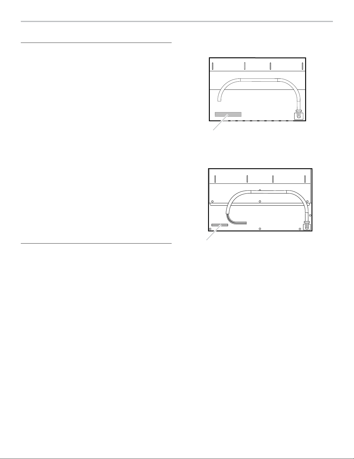
30" (76.2 cm) cooktop model/serial rating plate
location (model SIMU530)
A.Model/serial rating plate location
36" (91.4 cm) cooktop model/serial rating plate
location (model SIMU536)
Location Requirements
Make sure you have everything needed for correct installation. It
is the responsibility of the installer to comply with the installation
clearances specified in these instructions.
IMPORTANT: Observe all governing codes and ordinances.
When installing cooktop, use minimum dimensions given.
■ To eliminate the risk of burns or fire by reaching over the
heated surface units, cabinet storage space located above
the surface units should be avoided. If cabinet storage is to
be provided, the risk can be reduced by installing a range
hood that projects horizontally a minimum of 5” (12.7 cm)
beyond the bottom of the cabinets.
■ It is the installer’s responsibility to comply with installation
clearances specified on the model/serial rating plate. The
model/serial rating plate is located on the underside of the
cooktop burner box.
A.Model/serial rating plate location
■ Check the cooktop base for an approved installation label.
Verify approved oven model numbers that can be installed
with your cooktop model number. If you do not find this
label, your cooktop may not be approved for use over an
undercounter built-in oven. Contact your dealer to confirm
that your cooktop is approved.
■ Ovens approved for this type of installation will have an
approval label located on the top of the oven. If you do
not find this label, contact your dealer to confirm that your
oven is approved. Refer to oven manufacturer’s Installation
Instructions for approval for built-in undercounter use and
proper cutout dimensions.
■ When installing cooktop over an undercounter built-in oven,
do not fasten cooktop to countertop with clamps or seal
cooktop to countertop. This will make the cooktop easier to
remove if future servicing becomes necessary.
■ Use the countertop opening dimensions that are given
with these Installation Instructions. Given dimensions are
minimum clearances and provide 0” (0 cm) clearance.
■ Grounded electrical supply is required. See “Electrical
Requirements” section.
3
Page 4
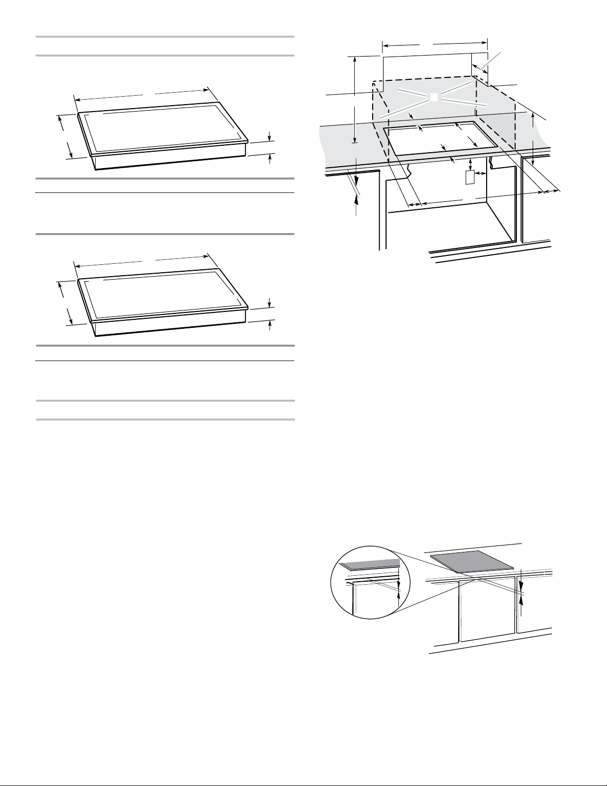
Product Dimensions
30" (76.2 cm) Cooktop
A
D
B
A
Model SIMU530
A. 215⁄16" (54.1 cm)
4
B. 30³⁄
" (78.2 cm)
8
C. 3¹⁄
" (8 cm)
36" (91.4 cm) Cooktop
B
A
Model SIMU536
A. 215⁄16" (54.1 cm)
5
B. 36
⁄16" (92.0 cm)
8
C. 3¹⁄
" (8 cm)
Cabinet Dimensions
IMPORTANT: If installing a range hood or microwave hood
combination above the range, follow the range hood or
microwave hood combination installation instructions for
dimensional clearances above the cooktop surface.
C
C
B
L
F
E
G
H
I
M
K
A. 29½" (75.0 cm) on 30" (76.2 cm) models
16
33¹⁄
" (84.0 cm) on 36" (91.4 cm) models
B. Combustible area above countertop (shown by dashed box above)
C. 30" (76.2 cm) minimum clearance between top of cooktop platform
C
and bottom of uncovered wood or metal cabinet (24" [61 cm]
minimum clearance if bottom of wood or metal cabinet is covered
by not less than ¹⁄
not less than No. 28 MSG sheet steel, 0.015" [0.04 cm] stainless
steel, or 0.024" [0.06 cm] aluminum or 0.020" [0.05 cm] copper)
D. 13" (33.0 cm) recommended upper cabinet depth
E. 2" (5.1 cm)
5
F. 19
⁄16" (49.0 cm)
G. 18" (45.7 cm) minimum clearance from upper cabinet to countertop
within minimum horizontal clearances to cooktop
H. Junction box or outlet; 12" (30.5 cm) minimum from bottom of
countertop
I. Junction box or outlet; 10" (25.4 cm) from right-hand side of
cabinet
J. 29½" (75.0 cm) on 30" (76.2 cm) models
16
33¹⁄
" (84.0 cm) on 36" (91.4 cm) models
K. 1" (2.5 cm) minimum distance to nearest left and right side
combustible surface above cooktop
L. 1" (2.5 cm) minimum clearance between back wall and countertop
M. IMPORTANT: For proper ventilation, provide a vent of ³⁄
under the countertop, in the front of the cabinet. The ventilation
opening is to extend the full length of the cooktop cutout. See the
following illustration.
4
" [0.6 cm] flame retardant millboard covered with
J
16
" (5 mm)
³⁄₁₆"
(5.0 mm)
M
NOTES: After you make the countertop cutout, some
installations may require notching down the base cabinet side
walls to clear the cooktop base. To avoid this modification, use a
base cabinet with sidewalls wider than the cutout.
8
If cabinet has a drawer, a 5¹⁄
" (13 cm) depth clearance from the
countertop to the top of the drawer (or other obstruction) in base
cabinet is required.
4
Page 5
Electrical Requirements
Center line
WARNING
Electrical Shock Hazard
Disconnect power before servicing.
Use 8 gauge copper wire.
Electrically ground cooktop.
Failure to follow these instructions can result in death,
fire, or electrical shock.
If codes permit and a separate ground wire is used, it is
recommended that a qualified electrical installer determine
that the ground path and wire gauge are in accordance with
local codes.
Check with a qualified electrical installer if you are not sure the
cooktop is properly grounded.
It is not recommended to have a fuse in the neutral or ground
circuit.
Make sure that the electrical connection and wire size are
adequate and in conformance with the National Electrical Code,
ANSI/NFPA 70-latest edition or CSA Standards C22.1-94,
Canadian Electrical Code, Part 1 and C22.2 No. O-M91-latest
edition, and all local codes and ordinances.
A copy of the above code standards can be obtained from:
National Fire Protection Association
One Batterymarch Park
Quincy, MA 02269
CSA International
8501 East Pleasant Valley Road
Cleveland, OH 44131-5575
■ If the house has aluminum wiring, follow the procedure
below:
1. Connect a section of solid copper wire to the pigtail
leads.
2. Connect the aluminum wiring to the added section
of copper wire using special connectors and/or tools
designed and UL listed for joining copper to aluminum.
Follow the electrical connector manufacturer’s recommended
procedure. Aluminum/copper connection must conform with
local codes and industry accepted wiring practices.
INSTALLATION INSTRUCTIONS
Prepare Location
1. Decide on the final location for the cooktop.
NOTE: Countertop must be 1³⁄
thick.
2. If necessary, make cutout in countertop before installing
cooktop. See “Location Requirements” section for more
information.
3. Clean cutout of any remaining dust and debris.
Install Brackets
NOTE: Cooktop Bracket Adhesive Kit Part Number W10310006
is required for installing the cooktop into a marble countertop.
See the “Assistance or Service” section of the Use and Care
Guide for information on ordering.
To Install Brackets into Marble Countertop:
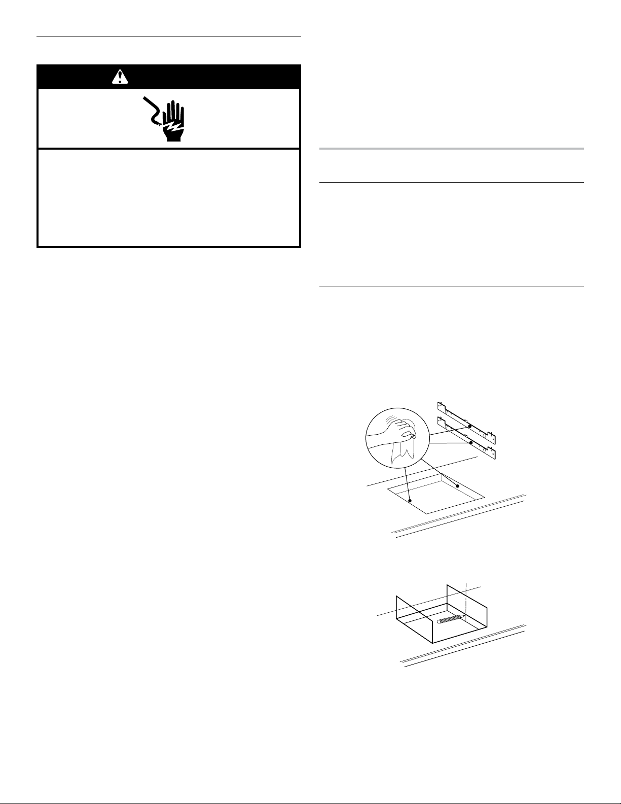
1. Clean the brackets and cooktop cutout of any dust
and debris.
16
" (3.0 cm) to 2" (5.1 cm)
Before You Make the Electrical Connection:
To properly install your cooktop, you must determine the type of
electrical connection you will be using and follow the instructions
provided for it here.
■ A 4-wire or 3-wire, single phase, 240 volt, 60 Hz., AC only
electrical supply is required on a separate, 50-amp circuit
(36" [91.4 cm] models) or 40-amp circuit (30" [76.2 cm]
models), fused on both sides of the line.
■ The cooktop should be connected directly to the junction
box through flexible, armored or nonmetallic sheathed,
copper cable. The flexible, armored cable extending from the
fuse box or circuit breaker box should be connected directly
to the junction box.
■ Locate the junction box to allow as much slack as possible
between the junction box and the cooktop so that the
cooktop can be moved if servicing becomes necessary in
the future.
■ Do not cut the conduit. The length of conduit provided is for
serviceability of the cooktop.
■ A UL listed or CSA approved conduit connector must be
provided at each end of the power supply cable (at the
cooktop and at the junction box). A listed conduit connector
is already provided at the cooktop.
2. Measure the center line of the vertical sides of the
cooktop cutout.
5
Page 6
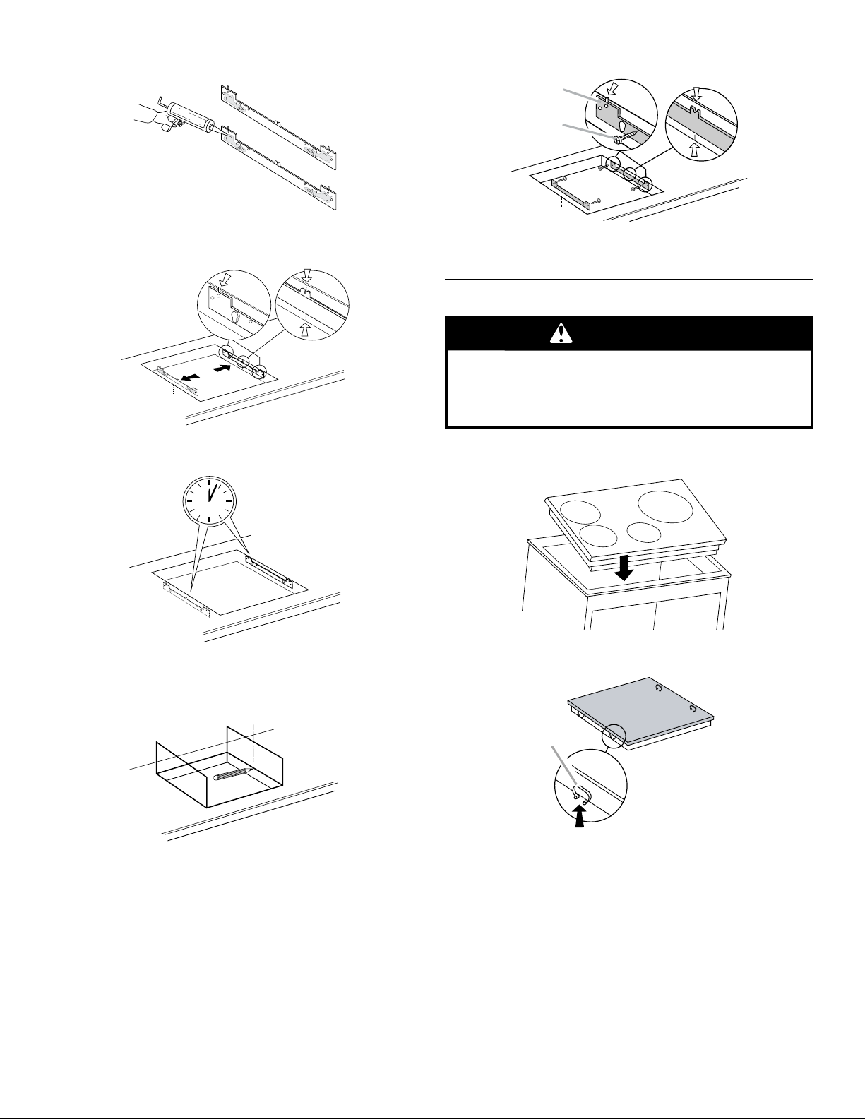
3. Apply the adhesive provided in the kit to the back side of
Center line
A
A
the brackets.
3. Attach the brackets in the cutout with the screws provided.
B
4. Position brackets in the center of the vertical centerline and
align the upper edge of the brackets so that they are flush
with the countertop.
5. Push the brackets firmly onto each side of the cooktop
cutout and wait 1 hour for adhesive to dry.
1 h
A. Bracket
B. Screw
Install Cooktop
WARNING
Excessive Weight Hazard
Use two or more people to move and install cooktop.
Failure to do so can result in back or other injury.
1. Using 2 or more people, lower the cooktop into the cutout
with the front end of the cooktop angled down.
2. Make sure that the clips on each side of the cooktop line up
To Install Brackets into Wood Countertop:
1. Measure the centerline of the vertical sides of the
cooktop cutout.
2. Position brackets in the center of the vertical centerline and
align the upper edge of the brackets so that they are flush
with the countertop.
with the brackets in the cutout.
A. Clip
6
Page 7
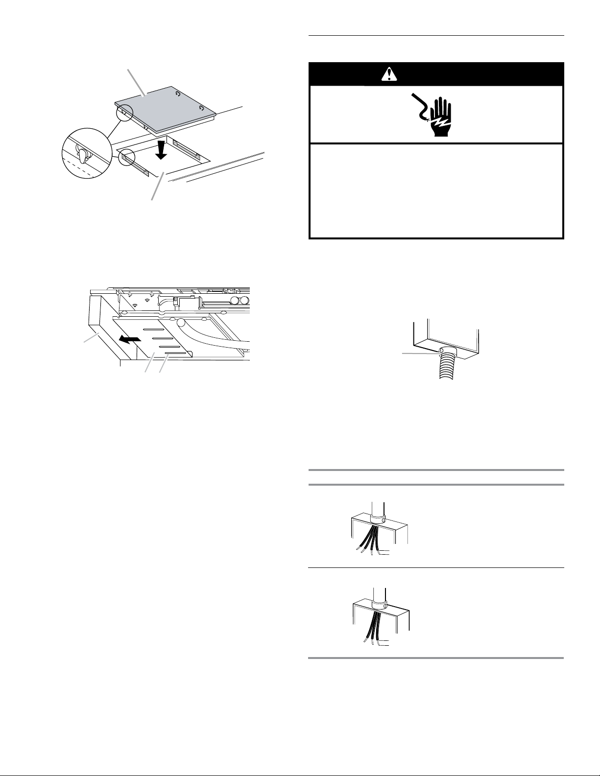
3. Push down on cooktop to snap the cooktop clips onto the
A
B
A
B
C
A
(1.3 cm)
(1.3 cm)
brackets installed in the cutout.
A. Induction cooktop
B. Cooktop cutout
4. On the underside of the cooktop, loosen the 4 screws
on the slider.
Make Electrical Connection
WARNING
Electrical Shock Hazard
Disconnect power before servicing.
Use 8 gauge copper wire.
Electrically ground cooktop.
Failure to follow these instructions can result in death,
fire, or electrical shock.
This cooktop is manufactured with a frame-connected, green (or
bare) ground wire.
1. Disconnect power.
2. Remove junction box cover if it is present.
3. Connect the flexible cable conduit from the cooktop to the
junction box using a UL listed or CSA approved conduit
connector.
A. Side of cabinet
B. Cooktop slider
C. Screw
5. Push the cooktop slider toward the side of the cabinet until
the slider and cabinet touch.
6. Tighten the screws on the slider.
A. UL listed or CSA approved conduit connector
4. Tighten screws on conduit connector if present.
5. See “Electrical Connection Options Chart” to complete
installation for your type of electrical connection.
Electrical Connection Options Chart
If your home has: Go to Section:
4-wire 4-Wire Cable from Home
Power Supply
½"
3-wire 3-Wire Cable from Home
Power Supply
½"
7
Page 8
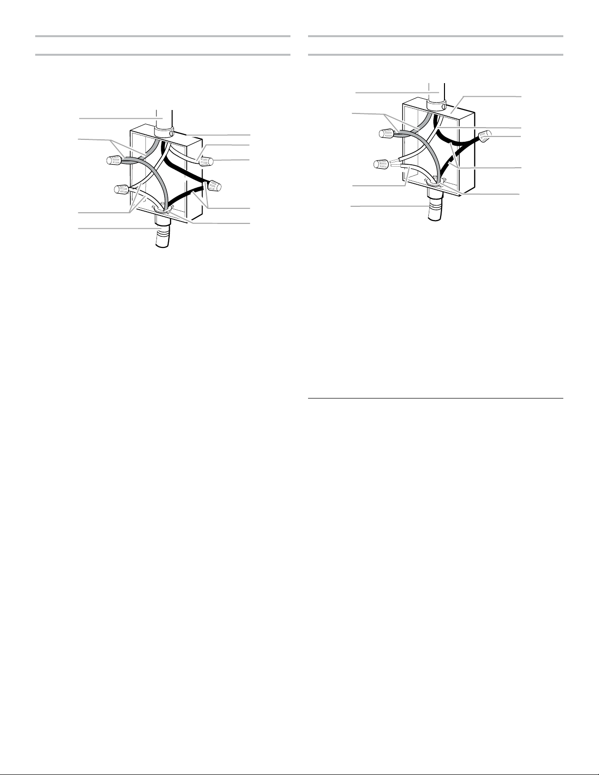
4-Wire Cable from Home Power Supply
B
C
D
D
3-Wire Cable from Home Power Supply - U.S.A. Only
IMPORTANT: Use the 4-wire cable from home power supply in
the U.S.A. where local codes do not allow grounding through
neutral, New Branch circuit installations (1996 NEC), mobile
homes and recreational vehicles, new construction, and
in Canada.
A
E
F
G
H
I
A. Cable from home power supply
B. Red wires
C. Green (or bare) ground wires
D. 3-Wire cable from cooktop
E. Junction box
F. White wire (from home power
supply)
G. UL listed wire connector
H. Black wires
I. UL listed or CSA approved
conduit connector with wire
bushing
1. Connect the 2 red wires (B) together using a UL listed wire
connector.
2. Connect the green (or bare) ground wire (C) from the cooktop
cable to the green (or bare) ground wire (in the junction box)
using a UL listed wire connector.
3. Put a UL listed wire connector on the end of the white
wire (F).
NOTE: Do not connect the green (or bare) ground wire to the
neutral (white) wire in the junction box.
4. Connect the 2 black wires (H) together using a UL listed wire
connector.
5. Install junction box cover.
IMPORTANT: Use the 3-wire cable from home power supply
where local codes permit a 3-wire connection.
A
E
B
F
G
H
C
I
A. Cable from home power supply
B. Red wires
C. Green (or bare) ground wire
from cooktop
D. 3-wire cable (from cooktop)
E. Junction box
F. White wire (from home power
supply)
G. UL listed wire connector
H. Black wires
I. UL listed or CSA approved
conduit connector with wire
bushing
1. Connect the 2 red wires (B) together using a UL listed wire
connector.
2. Connect the green (or bare) cooktop cable wire (C) to the
white (neutral) wire (F) in the junction box using a UL listed
wire connector.
3. Connect the 2 black wires (H) together using a UL listed wire
connector.
4. Install junction box cover.
Complete Installation
1. Check that all parts are now installed. If there is an extra
part, go back through the steps to see which step was
skipped.
2. Check that you have all your tools.
3. Dispose of/recycle all packaging materials.
4. Use a mild solution of liquid household cleaner and warm
water to clean cooktop before use. Dry thoroughly with a soft
cloth. For more information, see the “Cooktop Care” section
of the Use and Care Guide.
5. Read “Cooktop Use” in the cooktop Use and Care Guide.
6. Reconnect power.
NOTE: If the cooktop does not work after turning on the power,
check that a circuit breaker has not tripped or a household fuse
has not blown. See “Troubleshooting” section in the Use and
Care Guide for further information.
If you need Assistance or Service:
Please reference the “Assistance or Service” section of the Use
and Care Guide or contact the dealer from whom you purchased
your cooktop.
8
Page 9

W10818570A
SP PN W10825305
© 2015.
All rights reserved.
Tous droits réservés.
Printed in Italy
07/15
Imprimé en Italie
 Loading...