

Page 1

ISTRUZIONI PER L’USO
ED IL MONTAGGIO
INSTRUCTIONS FOR FITTING AND USE
INSTRUCTIONS DE MONTAGE ET D’UTILISATION
GEBRUIKS- EN MONTAGE-INSTRUCTIES
GEBRAUCHS- UND MONTAGEANWEISUNG
INSTRUCCIONES PARA EL USO Y MONTAJE
INSTRUKCJA OBSŁUGI I MONTAŹU
HASZNÁLATI ÉS BESZERELÉSI UTASÍTÁS
РУКОВОДСТВО К ПОЛЬЗОВАНИЮ И УСТАНОВКЕ
Piano di cottura ad induzione da incasso in vetroceramica con comandi
Touch Control
Built-in glass ceramic induction hob with Touch-Control switches
Plaque de cuisson vitrocéramique à induction avec commande Touch-Control
Vitrokeramische inbouw-inductiekookplaat met Touch-Control-bediening
Einbau-Glaskeramik-Induktionskochfeld mit Touch-Control-Bedienung
Encimera vitrocerámica por inducción incorporada con mando Touch Control
Indukcyjna kuchenka szkło-ceramiczna z systemem obsługi Touch-Control
Beépíthető kerámia-üveg indukciós főzőlap touch-control-kezeléssel
Встроенная индукционная кухонная плита с сенсорным управлением
223176 1
Page 2

You now own a glass ceramic hob with Touch-Control switches.
Chapters 2 and 3 of these Ope rating Instructions contain informat ion on how you can make sur e that your hob
provides many years of service.
These Operating Instructions are for use with several types of hobs. The nameplate on the front of these
Instructions will show you which type you have bought.
Contents
1. Operations
1.1 Your new hob
1.2 Touch-Control switches
1.3 Touch-Control operations
2. Things to watch out for
2.1 Imp ortant tips for induction
2.1.1 Induction cooking zones and mess tin
2.1.2 Protection against overheating
2.1.3 General
2.2 Important
3. Cleaning and Care
4. Fitting
4.1 Electrical connecti on
4.2 Maintenance and repair work
4.3 Working surface cut-out
4.4 Installation
10 223176
Page 3
1. Operations
1.1 Your new hob with Touch-Control operation
SE2664ID SE2774ID
Cooking zone Ind. 18 cm Ind. 18 cm
Cooking zone Ind. 14.5 cm Ind. 14.5 cm
Cooking zone Ind. 21 cm Ind. 21 cm
Cooking zone Ind. 14.5 cm Ind. 14.5 cm
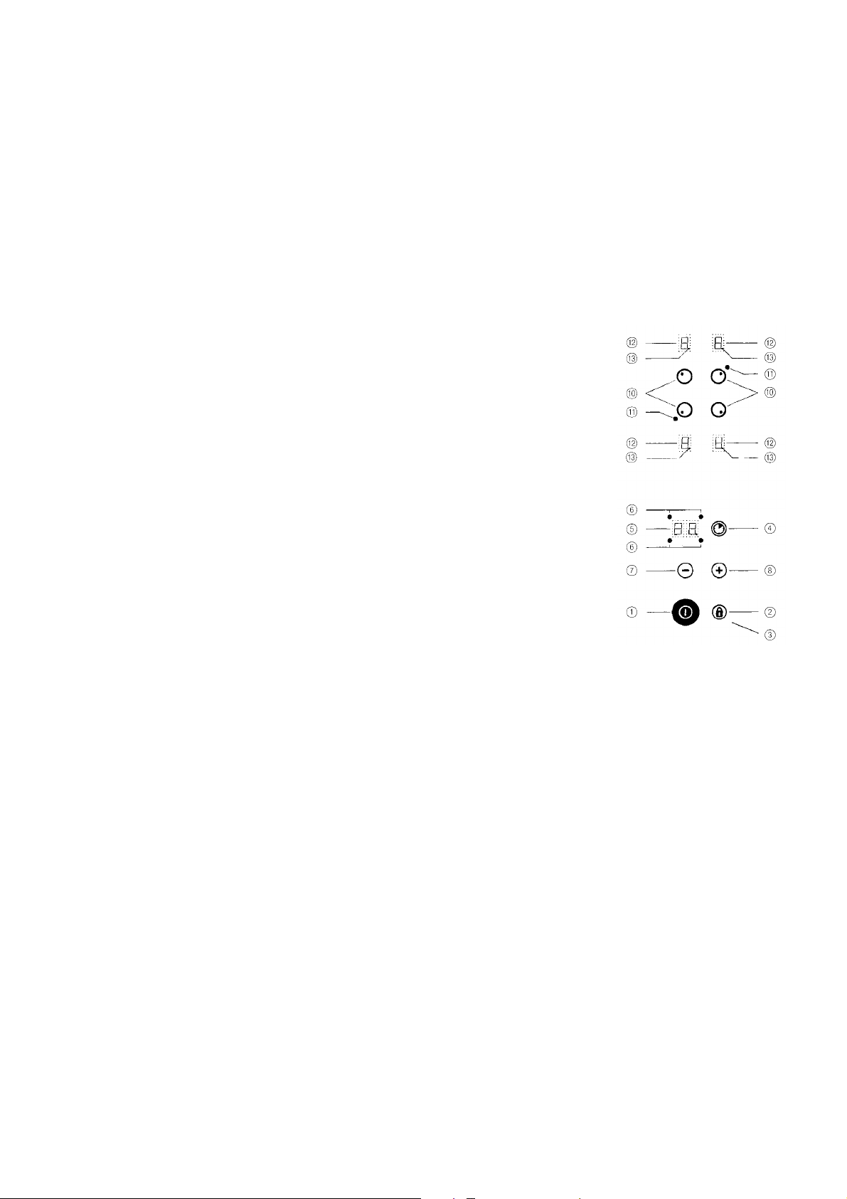
1.2 Touch-Control operating panel
After the supply voltage has been connected (mains connection), a self-test is carried out which is concluded when
a short acoustic signal is to be heard.
1
On/off switch (control)
2
Locking key
3
Control lamp lock (control)
4
Timer key
5
Time display
6
Timer control lam p
7
Minus key
8
Plus key
0
Cooking zone key
!
Control lamp for switching on the twin circuit
"
Cooking level display
§
Readiness point for cooking zone
(lit: cooking zone can be used)
1.3 Touch-Control operations
Each key operation is always confirmed by an acoustic signal.
Pressing the on/off switch key
at all of the cooking level displ ays and the cooki ng zone stan dby dot
out within ten seconds, otherwise the control system will automatically switch off again.
To switch on a cooking zon e, press the corresponding cooking zone key
appropriate stand-by dot cooking zone
Select a cooking level from 1 to 9 by means of the minus or plus keys
can be switched off again at any time. To do this, the required cooking zone must be activated, the stand-by dot
lights up.
The minus key
at the same time, the cooling level can be switched off directly.
In all cases the complete control syste m c an be swi tched off at any time by p r essi ng t he o n/o ff k ey
off the entire cooking range place your finger briefly on the on/off switch until the control lights go out.
Pressing lockin g key
mistake. Successful locking is indicated by the control lamp
again.
7 can be used to turn the cooling level down to "0"; if the minus and plus keys 7+8 are pressed
2 prevents all the keys - with the exception of th e on/off key - from being oper ated by
Residual heat display
The residual heat display is an illuminated "H" on the appropriate cooking level display ".
1 switches on the control system: Put your finger on the button until a "0" lights up
§ flashes. The next action m ust be carri ed
0 of the required cooking zone. T he
§ of the activated cooking zone lights up.
7/8. When switched on , each cook ing zone
1: To switch
3. Pressing the locking key 2 cancels this command
§
223176 11
Page 4

Pot Recognition (PR)
Tabl
An advantage of the induction heating method is pan detection. If there is no pan or a pan placed on the cooking
zone that is too small, then no energy is transmitted. If the cooking zone is switched on, the pan symbol "u" flashes
in the cooking level display
and it will switch on the selected level. In the same way, the power supply to the cooking zone is interrupted, if the
pan is removed from the cooking zone. If the pots and pans placed on the cooking zone are of smaller dimension,
and the pot detection still switches on, then the power supply will take place with less power.
". During the next 10 minutes the pan detection will identify a pan that has been placed
Power boost
For the induction cooking zone 3 an additional power boost can be activated for a fast
parboiling boost. Switc h on the cooking zo ne
zone button
plus key
induction cooking zone
minutes. This will be i ndi ca ted b y a "P ". S witc hi ng off the powe r lev el with the m inu s
7 puts the cooking zone a t cooking level 9. A fter ten minu tes the cookin g zone
key
is automatically switched fr om power lev el to cook ing level
the cooking zone
continuous changin g in the dis play betw een selected cooking range and decreased
cooking range. After switching back from the power mode, the cooking zone
provides the full power of 1200 W.
0. Select cookin g leve l 9 and switch on the power level by pressing the
8 once more. By activating this power mode, the power supply for the
3 will be increased to 30 00 W for a maximum time of 10
2 is decreased t o 600 W for this time. Th is will be indicated by
3 by means of cor respondin g cooki ng
9. The power supply for
2
Timer
The timer can be used to automatically switch off a cooking zone after a pre-set time of between 1 and 99 minutes.
The required cooking zone must be activated, stan d-by dot
means of the minus or plus keys
required cooking time between 1 and 99 minutes by means of the minus or plus keys
the selected cooking zone lights up.
The selected cooking time can be altered at any time. Activate the relevant cooking zone, press timer key
change the cooking time by means of the plus or minus keys
When the pre-set co oking tim e has finished, the cookin g zone s witches off automati cally a nd an acou stic si gnal
sounds for two minutes. This can be switched off by pressing any key.
If you want to switch the timer off beforehand, press cooking zone key
now be used to set the timer
and the plus keys
The timer can also be used as an egg timer when none of the cooking zones are activated. In this case, no cooking
zone should be activated when the timer
7/8.
7/8. Then press timer key 4. The timer display 5 shows "00". S elect the
5 to "00", or alternatively this can be done by the simultaneous pressing of the minus
4 is being set. (Stand-by dot cooking zone § does not light up?)
§ lights up. Sel ect a cooking level from 1 to 9 by
7/8. The control lamp 6 of
4 and
7/8.
0 and timer key 4. The minus key 7 can
Safety switch-off
Continuous operation of each individual cooking zone is
temporally limited by a s afety shut-off which switch es off the
cooking zone in ac cordance with the selected co oking level
after a specified ti me interval. The intervention times of this
safety device are included in the attached time table.
When the safety switc h-off has swi tched off the touch cont rol
system, a "0" is shown in the cooking level display
if there is still any residual heat left. Pressing the on/off switch
key makes the control system ready for operation again.
If more than one key is pressed simultaneously - with the
exception of the minus an d plu s k eys - the control system will
not accept this as a va lid command. If on e or more keys are
activated for longer than 30 seconds, for ex ample by boiling
over or the weight for a pan, the c ontr ol sy s tem as sume s that
there is an error and switches off automatically. If key
operation continues, a constant acoustic signal sounds.
12 223176
", or an "H"
e of times
MOT = maximum operating time,
in hours
Cooking level MOT (h)
16
26
35
45
54
61.5
71.5
81.5
91.5
Page 5

2. Things to watch out for
2.1 Important tips for induction
2.1.1 Induction cooking zones and mess tin
Your ceramic hob is equipped with induction cooking zones which are characterised by high performance when it
comes to quick heating and ene rgy saving. The heat is generat ed directly in the bottoms of the pots where it’s
needed, without a loss of energy through the ceramic hob. That’s why the energy consumption is lower than with
normal radiation heating elements.
The ceramic hob is not directly heated, though it becomes hot due to the effect of heat reflected by the pan. When
the cooking zones are switched off, a hot cooking zone is indicated by the flashing "H" (residual heat indicator). In
induction cooking zones, heating is achieved by means of an induction coil installed below the ceramic hob which
produces an electromagnetic field. With the use of magnetizable pans or dishes made of steel, steel mesh or iron
cast (suitable for induction ceramic hob), energy is transmitted directly to the bottom of the equipment.
Only use induction cooking zones with suitable cooking utensils, made of materials such as
steel, steel mesh or cast iron. Stainless steel pans with copper or aluminiu m bottoms and
glass pans are not suitable. When you purchase a set of pans, check for the label "Suitable
for induction".
2.1.2 Protection against overheating
The ceramic hob is provided with a protection against overheating, which protects the electronics against damage.
The protection ag ainst overheating works i n several stages. If there is a signific ant increase in th e heat of the
ceramic hob, then a two-stage fan switches on. If this is not enough, then the power level mode will be deactivated
and the power for the individual cooking zones decreased or switched off completely. Full power will be available
again once the ceramic hob has cooled down.
2.1.3 General
The best transmission is obtained when the pots and the cooking zone are of equal dimension. Always use a lid.
Energy is wasted if you cook without a lid placed correctly on the pan. Always take away overflow food.
Clean the hob before using it for the first time.
2.2 Important
Attention: The surfaces of the heating and cooking zones become hot du ring use. Keep
small children away at all times.
Always ensure that no hard objects are dropped onto the cooking surface. Under certain circumstances the
material is sensiti ve to mechanical stress es and strains. A heavy kno ck or blow in a small area can cause the
ceramic hob to break. If careless treatment results in a break, split or crack, the ceramic hob must immediately be
taken out of use and dis connected from the mains power supply. To do th is, switch off the safety swit ch for the
oven connection in the fuse box. Customer Service must be contacted.
Objects made out of metal, like knifes, f orks, spoons and lids should not b e placed on the
cooking zones, because they might become hot.
The cooking zone must be switched off after use by means of the touch control and not only
via pan detection. This is to avoid accidental activation.
Do not use the glass ceramic hob as a storage a rea! Nev er prep ar e foo d in alu mi niu m foi l a nd pl astic c onta in ers
on the hot cooking area.
Do not switch the hob on without using it for cooking. Do not place combustible, volatile or heat deformable objects
directly underneath the hob.
Overheated oil and fat can catch fire; for this reason, never leave food unattended which is cooked with fat or oil,
e.g. chipped potatoes. In add ition, make sure that leads from electrical app liances plugged into nearby sockets
cannot come into contact with the hot cooking zones.
Never clean the glass ceramic hob with a steam cleaner or similar appliance!
223176 13
Page 6

3. Cleaning and Care
Always clean the hob after it has cooled down. Even the slightest amount of
dirt will burn into the surface the next time you switch it on. Use only
recommended cleaners. Steel wool, cleaning sponges and abrasive
powders scratch the surface. Do not use oven sprays as these are
aggressive and damage the surface.
Light amounts of dirt
Use a damp cloth or a wa rm rinse to clean light amounts of dirt from the
surface. Rinse with cold water and then dry thoroughly. Use vinegar, lemon
juice or a calcium dissolving agent to remove water stains from the surface.
If these agents come into contact with the frame , wipe them off with a wet
cloth, otherwise the frame loses its gloss.
Heavy dirt
Use "Sidol Special for Stainless Steel", "Stahlfix" or "Cerafix" to remove
heavy dirt. Apply the cleaner with kitchen paper and rub it in. Leave it to take
effect than wipe off completely with cold water; then dry the surface
thoroughly. Cleaning residues on the surface can become aggressive when
the hob is reheated.
Persistent dirt and caking can best be rem oved with a glass scraper c
which can be obtai ned in hous ehold goods stores , pai nting and DIY s hops
or from our after-sales service. Pay attention to handle on purchasing. If you
buy a glass scraper, make sure that the handle is not made of plastic as this
will stick to the hot surface. Take care when using the scraper.
Food that contains sugar may permanently damage the glass ceramic
surface because they can produce scratches after they have become dry. In
order to prevent such surface damage, such substances must be
immediately removed with the glass scraper while they are still hot
d, e.
Changes to the colour of the ceramic surface
These have no effect on the function and stability of the glass ceramic.
These colour cha nges are not changes in the material but food residues
which were not removed and which have burnt in.
Metallic iridescent discolouring g is caused by wea r from pan b otto ms or
unsuitable cleaning agents. This discolouring can be removed with gr eat
difficulty with "Sidol Special for Stainless Steel" or "Stahlfix". You may have
to clean several times to remove the discolouring.
Worn decoration h. In time, the decoration will wear off and dark stains will
appear as a result of using aggressive cleaning agents and faulty pan
bottoms.
Remove melted sugar and food containing sugar immediately while still hot
with a glass scraper
e.
If cared for properly, your hob will remain beautiful for many years and
cleaning will be easier.
To care for your hob we recommend that you use "Cerafix". The high
silicone percentage of this cleaner creates a protective film which keeps off
water and dirt. All dirt remains on the film and can be removed easily. Clean
your hob and the cooking zones regularly.
c, otherwise dama ge ma y be caus ed to the s urfac e d,
14 223176
Page 7

4. Fitting
4.1 Electrical connection
(See page 1 of the Operating Instructions for the connection values and the model name)
This appliance may only be connected to the electricity supply by an approved electrician who must ensure
that the installation complies with the statutory regulations (Germany VDE, Austria ÖVE, Switzerland SEV,
etc.). The electrician must ensure that these regulations and those laid down by the local electricity supply
company are observed .
When connecting the electric al applianc e, instal l an all-pol e disconnec ting devi ce with a cont act gap o f at
least 3 mm. Make sure that the local mains voltage is the same as the voltage on the nameplate.
To connect the applian ce, unscrew the switchbox cover on the underside of the appliance to access the
terminal block. After connecting the appliance, replace the cover and secure the connection cable with the
strain relief clamp.
The connection cable must be at least HO5 VVF.
Make sure that the excess cable length is not laid in the hob’s installation area.
See Fig. 4 for the position of the cable cut-out.
Connection options
4.2 Maintenance and repair work
Before repair wo rk is carried out, disconne ct the appliance from the mains. If you have to contact our service
department, always quot e the type and make numbers. You can find these nu mbers on the nameplate or on
page 1 of the Operatin g Instructions. Eac h time the glass ce ramic hob is re moved from the work top, check the
seals and replace if necessary.
4.3 Working surface cut-out
Carry out all cut ting out of furniture units and worktops b efore fitt ing the ap pliance, and remove all sa wdust and
chips.
The dimensions of the worktop recess can be seen in the dimension drawing (Figs. 1+2).
The worktop and the hob must be fitted horizontally. A tilted hob is under tension and this increases the danger of
breaking.
223176 15
Page 8

4.4 Installation
Before installin g the hob, c heck that th e wraparound hob seal ha s no
gaps.
If the hob is installed in a worktop with a ceramic or similar cover (tiles),
remove the hob se al and seal the hob from the worktop with a p lastic
seal, such as heat-resistant silicone rubber.
Important! If the hob is installed above furniture parts (side
walls, drawers, etc.) it must be ensured that accidental contact
with the underside of the hob is prevented by means of a touch
guard. The touch guard may only be capable of removal with
suitable tools and must be attached to the underside of the
cooking surface at a minimum distance of 20 mm so that th e
mains connection cable does not touch the underside of the
cooking surface (Fig. 4). The back w all of the cabinet must be
open in order to provide for air circulation. Sufficient air supply
should be provided through the f urniture pedestal. The front
transverse strip of the furniture must be removed so that an
opening is provided for air f low underneath the worktop over
the entire width of the unit. The distance between induction hob
and kitchen furniture resp. built-in unit must provide for
sufficient ventilation of the induction. Thus a back-flow of
warmed air is prevented from entering the cool air intake.
Important! The screen shield must not cover the ventilation
openings. If necessary, shorten the shield up to the furniture or
built-in unit. Avoid excessive thermal development from below
e.g. from a baking oven without a cross flow cooling device.
No cross-bars may be in the area of the cut-out underneath.
Place the hob carefully into the cut-out and fasten it to the worktop with
the fasteners.
Screw the springs into the worktop as shown in the drawing. The hob is
then pressed carefully from above into the retaining springs.
When screwing the springs, always use the upper hole of the spring, unless the worktop is tiled. (Fig. 3)
In order to facilitate installation in worktops made of granite or similar material, we have included special
fastening springs, self-tapping screws and snap-on nuts (See drawings [Fig. 2a, 3a]).
Make sure that the worktop and the hob are horizonta l. In addition, make sure that no liquids can penetrate
between the edge of the hob and the worktop or between the hob and the wall and come into contact with any
electrical applian ces. Use seal ing s ecti ons, str ips, age nts, e tc. F or the p urpos es of fire s afety this appl ianc e is a
Type Y appliance . Thi s mea ns tha t it can be installed wit h i ts re ar si de and one of the other sides i n contact with
room or unit walls of any height. The other sides may only be in contact with furniture or other appliances with the
same height as the appliance.
16 223176
Page 9

Type: SE2664ID
Fastening in worktops made of wood
and similar material
Fig.1 Fig.2
Type: SE2774ID
Fig.1 Fig.2
Fig.4 Fig.3
1
Minimum distance to
adjacent walls
2
Cut-out di mension
3
Outside dimensions
of recess
4
Cable routing in
rear wall
Fastening in worktops made of granite or similar material
Fig.2a Fig.3a
223176 17
 Loading...