

Installation, Use
and Maintenance
Manual
OVEN HOOD SCF00032
Introduction
Dear Customer, we hereby thank you for
choosing our Oven Hood
and hope you will be satisfied with our product.
1. Instructions
The following instruction manual is an integral
part of the equipment
and must be at the operators’ disposal for
advice until the end of the life
cycle of the product.
Before carrying out any operations, carefully
read the information
contained in the manual about safe installation,
use and maintenance.
The equipment is only intended for the use it
has been designed for,
by qualified and skilled personnel.
Installation, maintenance and repair operations
must only be carried
out by an authorized technical service centre or
qualified personnel, in
compliance with the regulations in force and
according to the instructions
provided by the manufacturer.
When using it for the first time, make sure that
the hood conveyor
connected to the exhaust ducts of the oven is
positioned correctly, to
prevent vapour leakage. It is recommended to
make sure that the
connection between the ducts and the oven is
well sealed every time the
hood or the oven on which it is installed are
moved.
The equipment must be earthed in accordance
with the safety
regulations of the electrical system.
The plug to be connected to the power cable
must be compliant with
the regulations in force.
Do not block the openings, the heat ventilation
and exhaust slits.
Use the hood at an ambient temperature
between +5 °C and +35 °C.
This appliance is intended for professional use
and complies with the
EC directives in force. The appliance functions
as a condenser for the
exhaust vapours of the oven, therefore any
other use of the device is
improper.
The Manufacturer refuses all responsibility for
direct and indirect
damage caused by improper installation,
tampering with, inadequate
maintenance, improper use and failure to
comply with the regulations
contained in the instruction manual.
2. Installation
All the materials, with the exception of silicone,
used for installation
must resist a temperature of 150 °C without
generating strains and/or
surface defects.
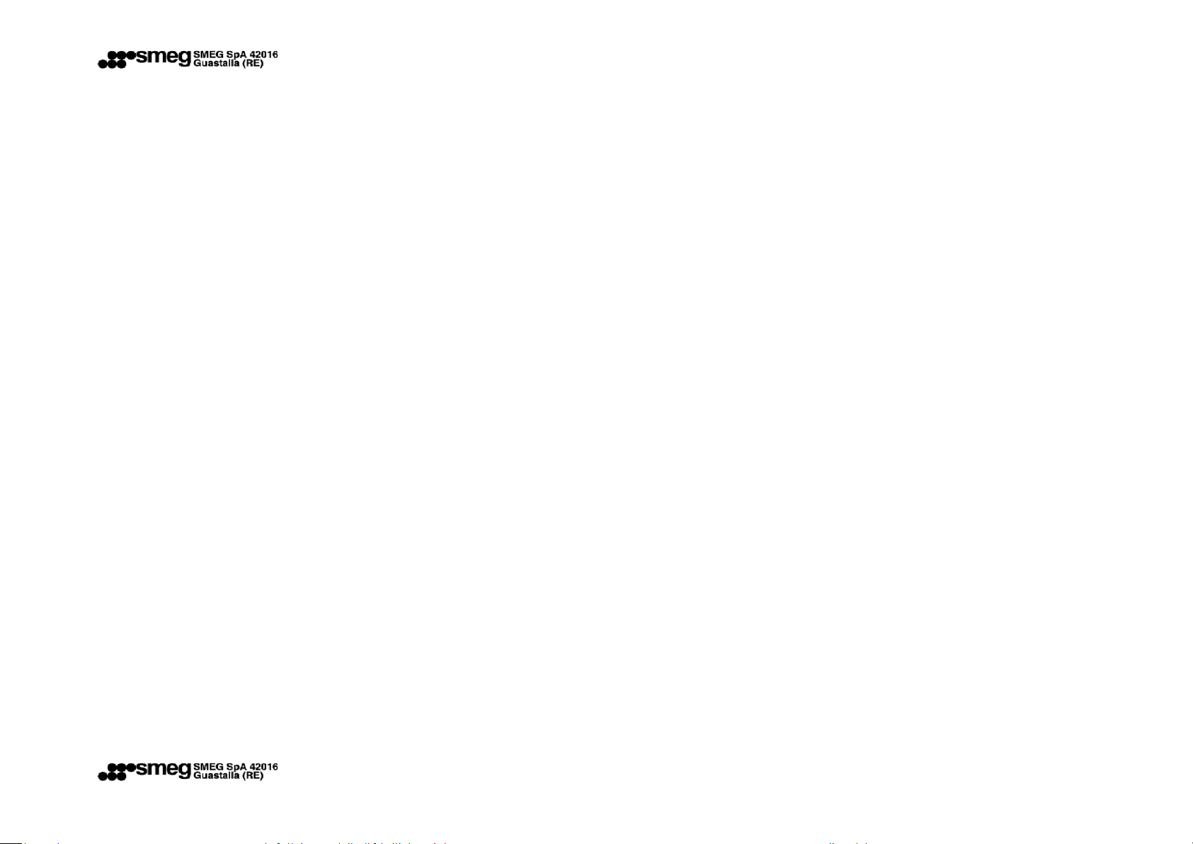
2.1 - Positioning
The Oven Hood must be positioned on the
oven, after must be
fixed by the two brackets, that will be fixed to
the rear oven’s back (Fig.
1).
2.2 - Electrical connection
The electrical
must be carried out by qualified personnel in
compliance with the
European regulations
The Ove is replaced, it must be compatible with
the maximum power of the
It is recommended to have the installation
done by a qualified electrician
in compliance with the regulations in force
Attention!!! – A bipolar safety switch must be
set upstream of the hood.
Attention!!! – The equipment must be earthed
properly according to the
safety regulations of the electrical system
connection, single phase 220 – 230 V ~ 50/60
Hz,in force.
en hood is supplied with electric cable and plug.
If the plug hood.
electrician,
force.
system.
fig.1
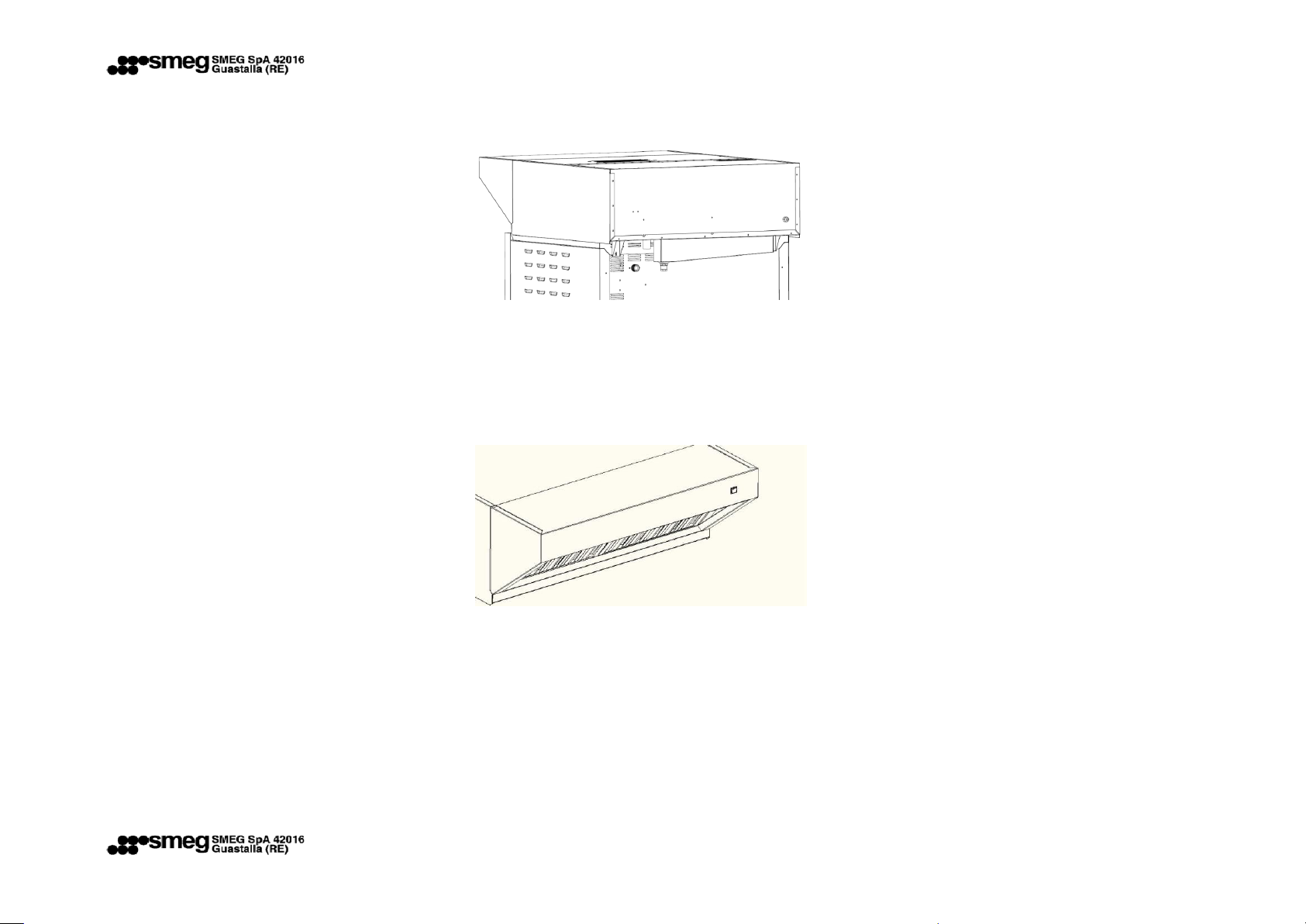
2.4 – Operation
The Oven Hood will be turned on by the front
switch (Fig.
Fig.2
3. Maintenance
Attention!!! – Before carrying out any
maintenance operations, turn off
the current by using the appropriate switch or
disconnecting the plug.
Attention!!! – Any maintenance operation
must be carried out by
qualified personnel only.
Maintenance operations may include the
removal of the rear

cover or the front one. To remove the front
cover unscrew the perimetric
screws (Fig. 3) and take care not to damage the
electric cables when
lifting the cover. To remove the rear cover
unscrew the perimetric screws
and lift the cover completely, taking care not to
disconnect the electric
cables.
Fig.3
Attention!!! – When removing the panels,
handle them with great
attention by using gloves to protect hands
from possible cuts.
3.1 – Disassembling labyrinth filters
To disassemble the filters, grab and slide them
mounted on the oven hood, fixed by screws
(Fig. 4).
upwards so that they
slip out of the lower guide. Rotate the lower
wall slightly to release the
filter completely. To reassemble the filters,
follow the procedure
reversely.
3.2 – Disassembling the fan
The fan is removed by removing the front cover
and disconnecting
the same from the cable. After removing the
front cover to which is
attached the fan you can proceed to remove
the screws that fixed the
fan to the front cover.
3.3 – Disassembling the switch ON OFF
Before removing the switch must be removed
fig.4
the cover panel
Attention!!! – Before closing back the
connections, make sure that the
electronic card has been replaced without
inverting the order of the
temperature feelers.
3.5 Spare parts
It is possible to use original or authorized spare
parts only. Do not
repair or replace any components of the oven
hood that have not been
recommended by this manual. All the other
interventions must be carried

out by authorized technical personnel. To ask
for a spare part, indicate
the hood model specified on the label.
The spare parts that can be supplied are the
following:
I. Switch ON OFF black 10 A;
II. Fan 7/7 - 145 W 4P;
III. Labyrinth filter 400 x 350 mm - GF032;
IV. Condensation Stopper.
4. Cleaning
Attention!!! – Never use detergents
containing: sand, caustic soda, acids
or chlorides that might corrode the surface.
Attention!!! – Carry out any cleaning
operation cutting off the power
supply first
The hood must be cleaned by using a damp
cloth with nonabrasive
detergent and drying the surfaces with a dry
cloth.
Serial number
year (2=2012) month (10= october) day
(30=day)
progressive products
2=decade of production
Fig. 6 – Electrical connection.
5. Label
 Loading...