

Page 1
Contents
1. Precautions for safety and use_________________________ 4
2. Instructions for disposal – our enviromental care___________ 5
3. Safety instructions __________________________________ 6
4. Fitting the appliance in the top _________________________ 7
4.1 Fixing to the supporting structure ________________________________________7
4.2 Fitting the adhesive foam rubber strip_____________________________________8
4.3 Fitting the fixing clips _________________________________________________8
4.4 Fitting the hob into the hole in the work-top ________________________________8
5. Electrical connection ________________________________ 9
5.1 Clearances above and around domestic appliances ________________________10
6. Gas connection ___________________________________ 12
6.1 Connection to liquid gas ______________________________________________12
6.2 Room ventilation____________________________________________________12
6.3 Combustion gas discharge ____________________________________________12
7. Adapting to different types of gas______________________ 13
7.1 Removing the hob skin _______________________________________________13
7.2 Burner and nozzle characteristics table __________________________________14
7.3 Hob burner layout ___________________________________________________14
7.4 Adjusting the primary air flow __________________________________________14
7.5 Reassembling the hob skin____________________________________________15
7.6 Adjusting the minimum setting for natural gas _____________________________15
7.7 Adjusting the minimum setting for liquid gas_______________________________15
7.8 Greasing the gas taps________________________________________________15
8. Description of controls ______________________________ 16
8.1 The front panel _____________________________________________________16
9. Using the hob _____________________________________ 17
9.1 Fitting the pan stands ________________________________________________17
9.2 Lighting burners with safety device______________________________________20
9.3 Practical hints for using the burners _____________________________________20
9.4 Pan diameters______________________________________________________20
10. Cleaning and maintenance_________________________ 21
10.1 Cleaning the hob____________________________________________________21
10.2 Cleaning instructions for an acid-etched glass hob _________________________21
10.3 Cleaning the components _____________________________________________21
Thank you for choosing our product.
We advise you to read this manual carefully. It contains all necessary instructions for
maintaining unaltered the appearance and functional qualities of the cooking hob.
INSTRUCTIONS FOR THE INSTALLER: these are intended for the authorized
person who is to check the gas supply system and install, commission and test the
appliance.
INSTRUCTIONS FOR THE USER: these provide recommendations for use, a
description of the controls and the correct procedures for cleaning and maintaining the
appliance.
3
Page 2
Precautions for Safety and Use
1. Precautions for safety and use
THIS MANUAL IS AN INTEGRAL PART OF THE APPLIANCE. TAKE GOOD CARE OF IT AND KEEP IT
TO HAND THROUGHOUT THE HOB'S LIFE CYCLE. USERS ARE ADVISED TO READ THIS MANUAL
AND ALL THE INSTRUCTIONS IT CONTAINS BEFORE USING THE HOB. ALSO KEEP THE SET OF
NOZZLES PROVIDED IN A SAFE PLACE. INSTALLATION MUST BE CARRIED OUT BY QUALIFIED
STAFF IN COMPLIANCE WITH THE RELEVANT REGULATIONS. THIS APPLIANCE IS INTENDED FOR
HOUSEHOLD USE AND COMPLIES WITH THE EEC DIRECTIVES CURRENTLY IN FORCE. THE
APPLIANCE IS BUILT TO PROVIDE THE FOLLOWING FUNCTION: COOKING AND HEATING FOODS;
ALL OTHER USES ARE TO BE CONSIDERED IMPROPER.
THE MANUFACTURER DECLINES ALL LIABILITY FOR USES OTHER THAN THOSE STATED ABOVE.
DO NOT USE THIS APPLIANCE FOR HEATING ROOMS
DO NOT DISCARD PACKING IN THE HOME ENVIRONMENT. SEPARATE THE VARIOUS WASTE
MATERIALS AND TAKE THEM TO THE NEAREST SELECTIVE WASTE COLLECTION CENTRE.
WHEN DISPOSING OF THE APPLIANCE IT MUST BE TAKEN TO A SELECTIVE WASTE COLLECTION
CENTRE.
DO NOT OBSTRUCT VENTILATION OPENINGS AND HEAT DISPERSAL SLITS.
DO NOT MODIFY THIS APPLIANCE.
DO NOT USE OR STORE FLAMMABLE MATERIALS IN THE APPLIANCE STORAGE DRAWER OR
NEAR THIS APPLIANCE.
THIS APPLIANCE IS DESIGNED FOR COOKING FOOD AND IT SHALL NOT BE USED AS A SPACE
HEATER.
DO NOT SPRAY AEROSOLS IN THE VICINITY OF THIS APPLIANCE WHILE IT IS IN OPERATION.
THE NAMEPLATE WITH THE TECHNICAL DATA, SERIAL NUMBER AND MARK IS IN A VISIBLE
POSITION UNDERNEATH THE CASING, ANNEXED TO THIS MANUAL AND APPLIED TO THE QUALITY
CERTIFICATE.
THIS NAMEPLATE MUST NEVER BE REMOVED.
4
Page 3

Instructions for disposal
2. Instructions for disposal – our enviromental care
Our product's packing is made of non-polluting materials, therefore compatible with the
environment and recyclable. Please help by disposing of the packing correctly. Find the
addresses of collection, recycling and disposal centres from your retailer or from the
competent local organisations.
Do not throw the packing or any part of it away. They can constitute a suffocation hazard
for children, especially the plastic bags.
Your old appliance also needs to be disposed of correctly.
Important: hand over your appliance to the local agency authorised for the collection of
household appliances no longer in use. Correct disposal means intelligent recycling of
valuable materials.
It is also necessary to cut the interconnecting cable to the power supply network, removing
it along with the plug.
5
Page 4
Safety instructions
3. Safety instructions
REFER TO THE INSTALLATION INSTRUCTIONS FOR THE SAFETY REGULATIONS FOR ELECTRIC
OR GAS APPLIANCES AND VENTILATION FUNCTIONS.
IN YOUR INTERESTS AND FOR YOUR SAFETY IT HAS BEEN ESTABLISHED BY LAW THAT THE
INSTALLATION AND SERVICING OF ALL ELECTRICAL APPLIANCES IS TO BE CARRIED OUT BY
QUALIFIED PERSONNEL IN ACCORDANCE WITH THE REGULATIONS IN FORCE.
OUR REGULAR INSTALLERS GUARANTEE A SATISFACTORY JOB.
GAS OR ELECTRIC APPLIANCES MUST ALWAYS BE DISCONNECTED BY SUITABLY SKILLED
PEOPLE.
IT IS OBLIGATORY FOR ALL ELECTRICAL SYSTEMS TO BE GROUNDED ACCORDING TO THE
METHODS REQUIRED BY SAFETY RULES.
THE PLUG TO BE CONNECTED TO THE POWER SUPPLY CABLE AND ITS SOCKET MUST BE OF
THE SAME TYPE AND CONFORM TO THE REGULATIONS IN FORCE.
THE SOCKET MUST BE ACCESSIBLE AFTER THE APPLIANCE IS BUILT IN.
NEVER UNPLUG BY PULLING ON THE CABLE.
IMMEDIATELY AFTER INSTALLATION, CARRY OUT A QUICK TEST ON THE HOB FOLLOWING THE
INSTRUCTIONS PROVIDED LATER IN THIS MANUAL. IF THE APPLIANCE FAILS TO OPERATE,
DISCONNECT IT FROM THE ELECTRICAL MAINS AND CONTACT YOUR NEAREST SERVICE
CENTRE.
NEVER ATTEMPT TO REPAIR THE APPLIANCE YOURSELF.
AFTER EACH USE OF THE HOB, ALWAYS CHECK THAT THE CONTROL KNOBS ARE TURNED TO
"ZERO" (OFF).
NEVER PLACE PANS WITH BOTTOMS WHICH ARE NOT PERFECTLY FLAT AND SMOOTH ON THE
HOB PAN STANDS.
NEVER USE PANS OR GRIDDLE PLATES WHICH PROJECT BEYOND THE OUTSIDE EDGE OF THE
HOB.
THE APPLIANCE BECOMES VERY HOT DURING USE. SUITABLE HEATPROOF GLOVES SHOULD BE
WORN FOR ALL OPERATIONS.
THE USE OF THIS APPLIANCE IS NOT PERMITTED TO PEOPLE (INCLUDING CHILDREN) OF
REDUCED PHYSICAL AND MENTAL ABILITY, OR LACKING IN EXPERIENCE IN THE USE OF
ELECTRICAL APPLIANCES, UNLESS THEY ARE SUPERVISED OR INSTRUCTED BY ADULTS OR
PEOPLE RESPONSIBLE FOR THEIR SAFETY.
WHERE THIS APPLIANCE IS INSTALLED IN MARINE CRAFT OR IN CARAVANS, IT SHALL NOT BE
USED AS A SPACE HEATER.
The manufacturer declines all responsibility for injury or damage caused by failure to comply
with the above regulations or deriving from tampering with even just one part of the appliance
and the use of non-original spare parts.
6
Page 5
Instructions for the Installer
If the hob has to be adapted for a type of gas different from the one for which it
is preset in the factory, make this adjusting before building it into the unit,
following the instructions in point “5. Adapting to different types of gas”.
The procedures required below must be carried out by a skilled builder and/or joiner.
The hob can be installed on various materials, including masonry, metal, solid wood
and wood finished with plastic laminates, provided the material is heat-resistant
(T 90° C).
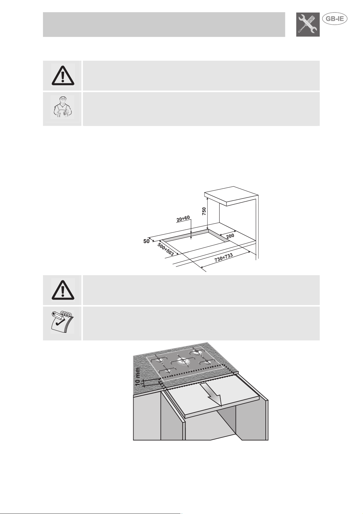
4.1 Fixing to the supporting structure
Make a hole in the cabinet top with the dimensions shown here, maintaining a
distance of at least 50 mm from the rear edge. This appliance may be installed
against walls higher than the worktop surface, provided the distance shown here is
maintained, in order to prevent damage due to overheating. Make sure that there is at
least 750 mm between the hob burners and a shelf or hood (if any) placed vertically
above them.
4. Fitting the appliance in the top
If the hob is installed above an oven, the oven must be fitted with a cooling fan.
If the hob is installed above a cupboard with doors, a separator panel must be
installed underneath it. Leave a gap of at least 10 mm between the bottom of the hob
and the surface of the panel, which must be easily removable to allow sufficient
access for any servicing procedures.
7
Page 6
Instructions for the Installer
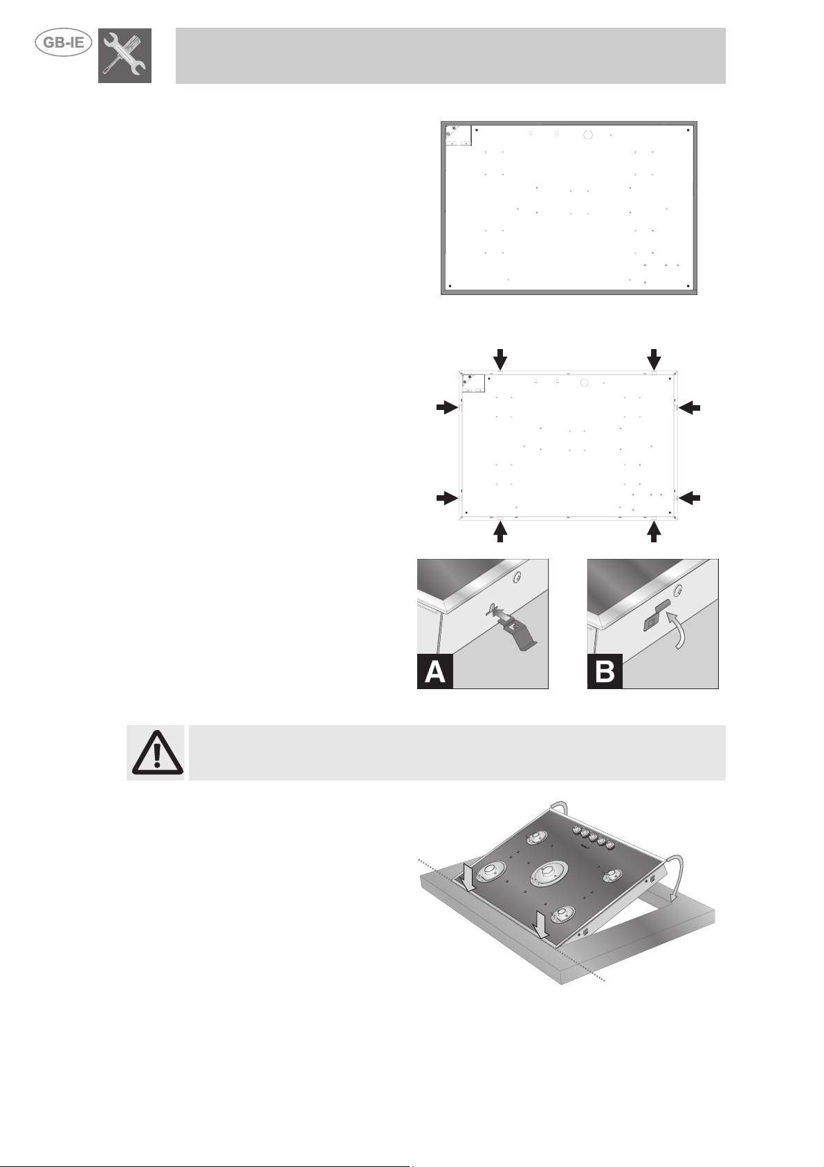
4.2 Fitting the adhesive foam rubber strip
Fit the adhesive foam rubber strip
(supplied with the hob) around the
outside edge of its surround.
It will act as a cushion between
the surface of the surround and
that of the cabinet. The diagram
on the right shows the correct
position for the foam rubber strip.
Take great care when fitting it to
ensure that it does not project
beyond the outside edge of the
frame.
4.3 Fitting the fixing clips
Fit the fixing clips in all the points
marked with an arrow. The clips
fix the hob an ensure that it is
centred correctly.
To fit the clips to the hob, simply
press them gently horizontally into
the groove provided (fig. A).
Then turn them upwards to fix
them permanently in place (fig. B).
4.4 Fitting the hob into the hole in the work-top
Take special care when fitting the hob into the work-top. If the procedures are not
carried out correctly, exactly as described, the hob may be damaged.
Before fitting the hob, remove
the pan stands (if fitted) and the
burners from the hob.
When fitting the hob, first rest the
surround entirely on the back
edge of the hole in the work-top.
Do not apply leverage to the
surround; since this part is very
delicate there is a risk of
damaging it.
Then lower the front of the hob
until the appliance is completely in
place.
8
Page 7

Instructions for the Installer
5. Electrical connection
Check that the power supply line voltage and size are as specified on the nameplate
underneath the appliance's casing. This nameplate must never be removed.
The plug on the end of the power supply lead and the wall socket must be of the same
type and comply with the relevant regulations. Check that the power supply line is
properly earthed.
Pass the power supply cable through the rear of the cabinet, taking care that it does not
touch the bottom case of the hob, or the oven (if any) built in underneath it.
If the appliance is connected to the power grid using a fixed connection, fit the power
line with an omnipolar circuit-breaker, in accordance with the installation instructions,
located in a readily accessible position near the appliance.
The use of reductions, adapters or junctions is not recommended.
If the power supply cable has to be replaced, the gauge of the wires in the new cable must
be at least 0.75 mm2 (3 x 0.75 cable), bearing in mind that the earth wire (yellow-green)
must be at least 20 mm longer at the end for connection to the appliance. Use only a type
H05V2V2-F or similar cable resistant to a temperature of up to 90°C. The cable must be
replaced by a qualified electrician, who must make the mains connection as shown below.
L = brown
N = blue
= yellow-green
The power supply lead must be replaced by an authorised service centre to prevent all
risks.
The manufacturer declines all responsibility for injury or damage caused by failure to
comply with the above regulations or deriving from tampering with even just one part
of the appliance.
9
Page 8

Instructions for the Installer
5.1 Clearances above and around domestic appliances
Extract from AS5601
REQUIREMENTS
3. Additional requirements for Freestanding and Elevated Cooking
1. Overhead clearances – (Measurement A)
Range hoods and exhaust fans shall be installed in accordance with the
manufacturer’s instructions. However, in no case shall the clearance between
the highest part of the hob of the cooking appliance and a range hood be less
than 600 mm or, for an overhead exhaust fan, 750 mm.
Any other downward facing combustible surface less than 600 mm above the
highest part of the hob shall be protected for the full width and depth of the
cooking surface area in accordance with Clause 5.12.1.2. However, in no
case shall this clearance to any surface be less than 450 mm.
2. Side clearances – (Measurements B & C)
Where B, measured from the periphery of the nearest burner to any vertical
combustible surface, is less than 200 mm, the surface shall be protected in
accordance with Clause 5.12.1.2 to a height C of not less than 150 mm
above the hob for the full dimension (width or depth) of the cooking surface
area. Where the cooking appliance is fitted with a ‘splashback’, protection of
the rear wall is not required.
Appliaces – (Measurements D & E)
Where D, the distance from the periphery of the nearest burner to a
horizontal combustible surface is less than 200 mm, then E shall be 10 mm
or more, or the horizontal surface shall be above the trivet. See insets above.
10
Page 9

Instructions for the Installer
1. Requirement 3 does not apply to a freestanding or elevated cooking appliance
NOTES
which is designed to prevent flames or the cooking vessels from extending
beyond the periphery of the appliance.
2. The ‘cooking surface area’ is defined as that part of the appliance
3. where cooking normally takes place and does not include those parts of the
appliance containing control knobs.
4. For definition of hob, see Clause 1.4.64.
5. For definition of trivet, see Clause 1.4.109.
6. Consideration is to be given to window treatments when located near cooking
appliances. See Clause 5.3.4.
11
Page 10

Instructions for the Installer
6. Gas connection
This appliance is suitable for installation with Natural Gas or
ULPG (propane/butane). Refer to page 12 for the relevant
burner pressure and appropriate injector sizes. When the
appliance is to be connected to Natural Gas then the pressure
regulator supplied must be fitted to the gas inlet. A test point (for
checking the gas pressure) is supplied either with the regulator
or as a separate fitting in the case of ULPG (propane/butane)
appliances.
Connection of the appliance to the gas supply must be in
accordance with the requirements of AS5601. A ½” BSP
connector at the inlet is recommended and the gas supply line
to the appliance must be of adequate length to allow sufficient
withdrawal of appliance for service or disconnection and be:
1. annealed copper pipe or;
2. flexible hose according to AS/NZ1869 & be at least Class “B”, 10 mm diameter.
The appliance must be installed with provision to allow the gas to be turned off and
disconnected for servicing and removal of the appliance as required from the gas
supply. Before the appliance is operated make certain all relevant parts are placed in
the correct position. When the installation is completed the installation connections of
appliance will require to be leak tested, the burner operating pressure and flame
checked and adjusted. Warranty service calls do not cover these adjustments! To check
the operating pressure of the appliance it is recommended at least 2 large size burners
are used. Ensure appliance is secured to wall when installation is completed. N.G. The
regulator supplied must be fitted to the ½ BSP thread at the rear of the appliance. An
approved manual shut-off valve must be installed. The N.G. regulator must be checked
and adjusted to 1.0kPa after installation.
U.L.P.G. Can be connected to the inlet fitting directly. The
pressure must be checked to ensure it is operating at
2.75kPa. A separate test point fitting must be installed
between the piping & the appliance for the pressure to be
checked to ensure it is operating at 2.75kPa.
Installation with the flexible hose must be carried out so that the length of the piping
does not exceed 2 metres fully extended; make sure that the hoses do not come into
contact with moving parts and that they are not crushed in any way.
6.1 Connection to liquid gas
Use a pressure regulator and make the connection on the gas cylinder following the
guidelines established by the regulations in force. Make sure that the feed pressure
complies with the values indicated in the table at point “9.2 Burner and nozzle
characteristics table”.
6.2 Room ventilation
Caution – This hob may only be installed and operated in rooms permanently
ventilated in accordance with current regulations. For proper operation of a gas
appliance it is essential for the air necessary for combustion of the gas to be able to
flow naturally into the room. Air must flow directly into the room through openings in its
outside walls. This (these) opening (s) must have a free passage cross-section of at
least 100 cm2, or 200 cm2 for appliances not equipped with gas safety device. These
openings must be constructed so that they cannot be obstructed indoors or outdoors,
and should preferably be close to the floor on the side opposite to the combustion gas
discharge point. If it is not possible to make the openings in the room where the
cooker is installed, the necessary air may be taken from an adjoining room, proveded
it is not a bedroom or a room with fire risk.
6.3 Combustion gas discharge
Combustion gases may be discharged by means of hoods connected to a flue with
reliable natural draught, or a fan extraction system. An effective extraction system requires
careful design by an authorised specialist, and must comply with the regulation distances
and positions. After installation, the engineer must issue a certificate of compliance.
12
Page 11

Instructions for the Installer
7. Adapting to different types of gas
The operations described below must be carried out with the appliance not
built-in and not connected to the gas or electricity supply.
The appliance is tested with NG (2H) natural gas at the pressure of 1 kPa.
If it is to be used with other types of gas, the burner nozzles have to be changed
and the primary air flow adjusted.
To replace the nozzles and adjust the burners, the hob skin has to be removed.
Proceed as described below.
7.1 Removing the hob skin
Remove all the burner components in the numerical order shown below:
• Pull off all the knobs.
• Lift all the burner
components off the hob.
1
• Remove the cover plate
of each burner by
undoing the screws.
2
• Remove the hob skin
fixing screws, taking care
only to remove the
screws shown on the
right.
3
• After removing all the
components described
above, lift off the hob
skin.
4
13
Page 12

Instructions for the Installer
7.2 Burner and nozzle characteristics table
Burner ULPG – 2.75 kPa
Nominal gas consumption
(MJ/h)
Auxiliary 4.1 0.54
Semi rapid 6.0 0.67
Rapid 11.2 0.85
Ultra Rapid 15.1 1.05
Injector
(mm)
Burner Natural Gas – 1.0 kPa
Nominal gas consumption
(MJ/h)
Auxiliary 4.5 0.98
Semi rapid 6.1 1.10
Rapid 10.8 1.45
Ultra Rapid 15.1 1.70
Injector
(mm)
7.3 Hob burner layout
Burner type
1 Auxiliary
2 Semi rapid
3 Rapid
4 Ultra rapid
14
7.4 Adjusting the primary air flow
Refers to the gap “X” in mm.
BURNER
Auxiliary
Semi rapid
Rapid
Ultra Rapid
ULPG
1.0 kPa
9.5 2
1 2
3 3
open 5
To identify the burners on your hob, refer to the drawings in point “7.3 Hob burner
layout”.
Natural Gas
2.75 kPa
Page 13

Instructions for the Installer
7.5 Reassembling the hob skin
Reverse the procedure described in point “7.1 Removing the hob skin”.
When replacing the cover plates, check that the seals are fitted correctly.
Fit the pan stands as described in point 9.1Fitting the pan stands.
7.6 Adjusting the minimum setting for natural gas
Reassemble the components on the burner and fit the
knobs onto the tap rods.
Light the burner and turn it to the minimum
setting.
Remove the knob again and adjust the regulator
screw inside or beside the tap rod (depending on the
model) until an even minimum flame is obtained.
Put the knob back in place and check the stability of
the burner flame (the flame must not go out when the
knob is turned quickly from the maximum to the
minimum setting).
7.7 Adjusting the minimum setting for liquid gas
Use a pressure regulator and make the connection on the gas cylinder following the
guidelines established by the regulations in force.
Make sure that the feed pressure complies with the values indicated in the table at
point “7.2 Burner and nozzle characteristics table”.
7.8 Greasing the gas taps
Over time, the gas taps may become stiff or jam. Clean their insides and change their
lubricating grease. This operation must be carried out by a skilled technician.
15
Page 14
Instructions for the User
8. Description of controls
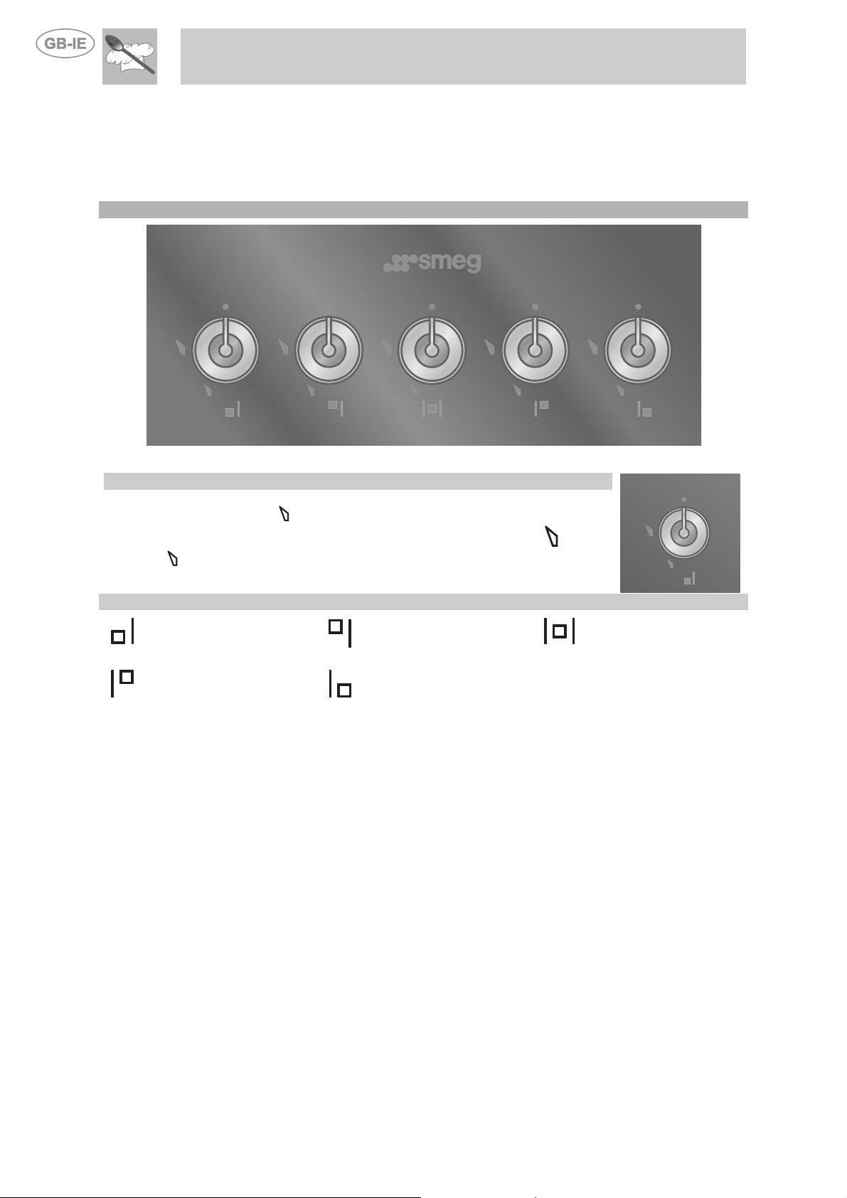
8.1 The front panel
All the hob's control and monitoring devices are placed together on the front panel.
CONTROL AREA
5 Burner Hob
KNOB OPERATING MODE
To light the flame, press the knob and at the same time turn it anti-clockwise to
the minimum flame symbol .
To adjust the flame, turn the knob to the zone between the maximum and the
minimum settings.
To turn off the burner, turn the knob back to the O position.
Front left-hand burner
Rear right-hand burner
BURNER LAYOUT - Key to symbols
Rear left-hand burner
Front right-hand burner
Middle burner
16
Page 15

Instructions for the User
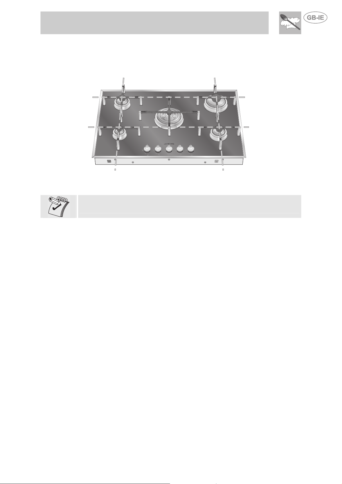
9. Using the hob
Check that the fixing cover plates E, the
burners, the flame diffuser rings and the pan
stands are fitted correctly.
The projections A on the flame diffuser rings
must be fitted into the recesses B in the burner.
The holes C in the burner must mate with the
ignition plugs and thermocouples D on the hob.
9.1 Fitting the pan stands
The pan stands are supplied dismantled from the hob. To place each pan stand on its
burner correctly, follow the instructions provided below:
Each rack must be positioned on the corresponding burner in
order to guarantee proper operation.
Be very careful to match the different central diameters of the
racks to the flame-spreader crowns.
17
Page 16

Instructions for the User
At the ends of the legs of the racks there are
silicone rests with a hole that must be centred
onto the matching fixing pins on the hob.
Make sure that the pan stands are simply fitted over their burners, and are not
left in a raised or tilted position; if this occurs, repeat the fitting procedure.
To position the rack, you first need to centre
the fastening pins (1) and (2) and then lower it
until it is resting on the hob.
When properly positioned, the legs of the racks
must not be suspended above the hob but
should rest on top of it.
WRONG RIGHT
WRONG RIGHT
18
Page 17
Instructions for the User
After performing the operations described above (for each pan stand), the hob will be
as shown below, with the feet of the pan stands forming a pattern of horizontal and
vertical lines.
If a pan wobbles noticeably, check that the pan stands have not been fitted
incorrectly.
19
Page 18

Instructions for the User
9.2 Lighting burners with safety device
The burner it controls is shown next to each knob (the example here shows the front
left-hand burner).
The appliance is equipped with electronic ignition. Simply press the knob and turn it
anti-clockwise to the minimum flame symbol , until the burner lights. Keep the knob
pressed down for about 2 seconds to keep the flame alight and prime the safety
device. The burner may go out when the knob is released. In this case, repeat the
operation, keeping the knob pressed down for longer.
When the burner has lit, its control knob will light up to confirm that it is in operation.
The knob will go out a few seconds after it is turned to the O position, or if the burner
goes out accidentally. The knob light comes on and goes out gradually.
If the burners should go out accidentally the safety device will be tripped about 20
seconds later, cutting off the gas supply even if the gas tap is open.
9.3 Practical hints for using the burners
For better burner efficiency and to minimise gas consumption, use flat,
even -bottomed pans with lids of suitable size for the burner (see point
"9.4 Pan Diameters").
When cooking, to prevent burns or damage to the hob all pans or
griddle plates must be placed inside the perimeter of the hob and must
be at least 5-7 cm from the knobs.
9.4 Pan diameters
BURNERS min. and max.
Ø
1 Auxiliary
2 Semi rapid
3 Rapid
4 Ultra Rapid
(in cm)
7-18
10-24
18-24
20-28
20
Page 19

Instructions for the User
10. Cleaning and maintenance
Before carrying out any operations, disconnect the appliance from the
electricity supply.
Never use a jet of steam for cleaning the appliance.
10.1 Cleaning the hob
To keep the hob in good condition, it must be cleaned regularly, after each use, first
allowing it to cool.
10.1.1 Routine daily glass hob cleaning
When cleaning and caring for glass surfaces always use only specific products which
do not contain abrasives or chlorine-based acids.
Instructions for use: pour the product onto a damp cloth and wipe over the surface,
then rinse thoroughly and dry with a soft cloth or chamois leather.
10.1.2 Food stains or spills
Never use metal scouring pads or sharp scrapers which will damage the
surface.
Use ordinary non-abrasive products for glass, with the aid of nonscratching sponges and wooden or plastic utensils if necessary.
Rinse thoroughly and dry with a soft cloth or chamois leather.
10.2 Cleaning instructions for an acid-etched glass hob
10.2.1 Grease
Use washing up liquid and a microfibre cloth.
10.2.2 Rings and encrustations
Use stainless steel cream or mildly abrasive creams; leave the product to act for a few
minutes, then wipe away with a microfibre cloth.
10.2.3 Stubborn encrustations
If using the microfibre cloth is not enough, a brass wire sponge can be used together
with stainless steel cream or standard abrasive creams available in shops.
To avoid encrustations which are difficult to remove, you are advised to clean
the hob every time you finish cooking.
10.3 Cleaning the components
Never clean the knobs with aggressive products containing alcohol or steel or glass
cleaners, since they might cause permanent damage.
NEVER REMOVE THE FIXING COVER PLATES TO CLEAN THE HOB.
The components described below must never be washed in a dishwasher.
21
Page 20

Instructions for the User
10.3.1 The knobs
The knobs must be cleaned with a soft cloth dipped in warm water and dried
thoroughly. They can easily be lifted off.
10.3.2 The pan stands
Remove the pan stands and wash them in warm water with a non-abrasive detergent,
taking care to remove all deposits. Replace them on the hob following the instructions
provided in point “
10.3.3 The flame diffuser rings
The burner caps and flame diffuser rings can be removed for easier cleaning; wash
them in hot water and non-abrasive detergent, taking care to remove all deposits, and
wait for them to dry completely.
The burner pins A must be fitted into the recesses B in the flame diffuser ring. The
holes C in the flame diffuser ring must mate with the ignition plugs and thermocouples
D on the hob.
10.3.4 The plugs and thermocouples
For best performance, the ignition plugs and thermocouples must always be kept
thoroughly clean. Check them frequently and if necessary clean them with a wet cloth.
Remove any dry residues with a wooden toothpick or a needle.
9.1Fitting the pan stands”.
914773752/ D
22
 Loading...