

Contents
1. INSTRUCTIONS FOR USE .................................................................... 4
2. INSTRUCTIONS FOR DISPOSAL – OUR ENVIRONMENTAL CARE... 5
3. SAFETY INSTRUCTIONS ...................................................................... 6
4. KNOW YOUR APPLIANCE .................................................................... 7
5. USING THE HOB.................................................................................... 8
6. CLEANING AND MAINTENANCE ........................................................ 10
7. INSTALLING THE APPLIANCE............................................................ 11
8. GAS CONNECTION ............................................................................. 19
9. ADAPTATION TO DIFFERENT TYPES OF GAS................................. 21
10. FINAL OPERATIONS FOR GAS APPLIANCES................................... 23
Thank you for choosing our product.
We advise you to read this manual carefully. It contains all necessary
instructions for maintaining unaltered the appearance and functional
qualities of the cooking hob.
INSTRUCTIONS FOR THE INSTALLER: these are intended for the authorized person who is to check the gas supply system and install, commis-
sion and test the appliance.
INSTRUCTIONS FOR THE USER: these provide recommendations for
use, a description of the controls and the correct procedures for cleaning
and maintaining the appliance.
3
Precautions for use
1. INSTRUCTIONS FOR USE
THIS MANUAL IS AN INTEGRAL PART OF THE APPLIANCE. IT MUST BE KEPT
IN ITS ENTIRETY AND IN AN ACCESSIBLE PLACE FOR THE WHOLE
WORKING LIFE OF THE HOB.
WE URGE YOU TO READ THIS MANUAL AND ALL THE INFORMATION IT
CONTAINS CAREFULLY BEFORE USING THE APPLIANCE.
INSTALLATION MUST BE CARRIED OUT BY QUALIFIED PERSONNEL IN
ACCORDANCE WITH THE REGULATIONS IN FORCE. THIS APPLIANCE IS
INTENDED FOR DOMESTIC USES AND CONFORMS TO THE EEC
DIRECTIVES CURRENTLY IN FORCE. THE APPLIANCE HAS BEEN BUILT TO
CARRY OUT THE FOLLOWING FUNCTIONS: COOKING AND HEATING-UP OF
FOOD; ALL OTHER USES ARE CONSIDERED IMPROPER.
THE MANUFACTURER DECLINES ALL RESPONSIBILITY FOR IMPROPER
USE.
DO NOT USE THIS APPLIANCE FOR HEATING ROOMS.
DO NOT DISCARD PACKING IN THE HOME ENVIRONMENT. SEPARATE THE
VARIOUS WASTE MATERIALS AND TAKE THEM TO THE NEAREST
SELECTIVE WASTE COLLECTION CENTRE.
WHEN DISPOSING OF THE APPLIANCE IT MUST BE TAKEN TO A SELECTIVE
WASTE COLLECTION CENTRE.
DO NOT OBSTRUCT VENTILATION OPENINGS AND HEAT DISPERSAL SLITS.
DO NOT MODIFY THIS APPLIANCE.
DO NOT USE OR STORE FLAMMABLE MATERIALS IN THE APPLIANCE
STORAGE DRAWER OR NEAR THIS APPLIANCE.
THIS APPLIANCE IS DESIGNED FOR COOKING FOOD AND IT SHALL NOT BE
USED AS A SPACE HEATER.
DO NOT SPRAY AEROSOLS IN THE VICINITY OF THIS APPLIANCE WHILE IT
IS IN OPERATION.
THE IDENTIFICATION PLATE WITH THE TECHNICAL DATA, SERIAL NUMBER
AND MARK IS IN A VISIBLE POSITION UNDER THE CASING.
THE PLATE MUST NOT BE REMOVED.
4

Instructions for disposal
2. INSTRUCTIONS FOR DISPOSAL – OUR ENVIRONMENTAL CARE
Our product's packing is made of non-polluting materials, therefore
compatible with the environment and recyclable. Please help by disposing
of the packing correctly. Find the addresses of collection, recycling and
disposal centres from your retailer or from the competent local
organisations.
Do not throw the packing or any part of it away. They can constitute a
suffocation hazard for children, especially the plastic bags.
Your old appliance also needs to be disposed of correctly.
Important: hand over your appliance to the local agency authorised for
the collection of household appliances no longer in use. Correct disposal
means intelligent recycling of valuable materials.
It is also necessary to cut the interconnecting cable to the power supply
network, removing it along with the plug.
5

Safety instructions
3. SAFETY INSTRUCTIONS
REFER TO THE INSTALLATION INSTRUCTIONS FOR THE SAFETY
REGULATIONS FOR ELECTRIC OR GAS APPLIANCES AND VENTILATION
FUNCTIONS.
IN YOUR INTERESTS AND FOR YOUR SAFETY IT HAS BEEN ESTABLISHED
BY LAW THAT THE INSTALLATION AND SERVICING OF ALL ELECTRICAL
APPLIANCES IS TO BE CARRIED OUT BY QUALIFIED PERSONNEL IN
ACCORDANCE WITH THE REGULATIONS IN FORCE.
OUR REGULAR INSTALLERS GUARANTEE A SATISFACTORY JOB.
GAS OR ELECTRIC APPLIANCES MUST ALWAYS BE DISCONNECTED BY
SUITABLY SKILLED PEOPLE.
THE PLUG TO BE CONNECTED TO THE POWER SUPPLY CABLE AND ITS
SOCKET MUST BE OF THE SAME TYPE AND CONFORM TO THE
REGULATIONS IN FORCE.
THE SOCKET MUST BE ACCESSIBLE AFTER THE APPLIANCE IS BUILT IN.
NEVER UNPLUG BY PULLING ON THE CABLE.
IT IS OBLIGATORY FOR ALL ELECTRICAL SYSTEMS TO BE GROUNDED
ACCORDING TO THE METHODS REQUIRED BY SAFETY RULES.
IMMEDIATELY AFTER INSTALLATION CARRY OUT A BRIEF INSPECTION
TEST, FOLLOWING THE INSTRUCTIONS BELOW. SHOULD THE APPLIANCE
NOT FUNCTION, DISCONNECT IT FROM THE ELECTRICITY SUPPLY AND
CALL THE NEAREST TECHNICAL ASSISTANCE CENTRE.
NEVER ATTEMPT TO REPAIR THE APPLIANCE.
THE APPLIANCE BECOMES VERY HOT DURING USE. SUITABLE HEATPROOF GLOVES SHOULD BE WORN FOR ALL OPERATIONS.
THE USE OF THIS APPLIANCE IS NOT PERMITTED TO PEOPLE (INCLUDING
CHILDREN) OF REDUCED PHYSICAL AND MENTAL ABILITY, OR LACKING IN
EXPERIENCE IN THE USE OF ELECTRICAL APPLIANCES, UNLESS THEY ARE
SUPERVISED OR INSTRUCTED BY ADULTS OR PEOPLE RESPONSIBLE FOR
THEIR SAFETY.
WHERE THIS APPLIANCE IS INSTALLED IN MARINE CRAFT OR IN
CARAVANS, IT SHALL NOT
ALWAYS CHECK THAT THE CONTROL KNOBS ARE IN THE 0 (OFF) POSITION
WHEN YOU FINISH USING THE APPLIANCE.
BE USED AS A SPACE HEATER.
The manufacturer declines all responsibility for damage to persons or
things caused by the non-observance of the above prescriptions or
deriving from tampering with any part of the appliance or by the use of
non-original spares.
6
Instructions for the User
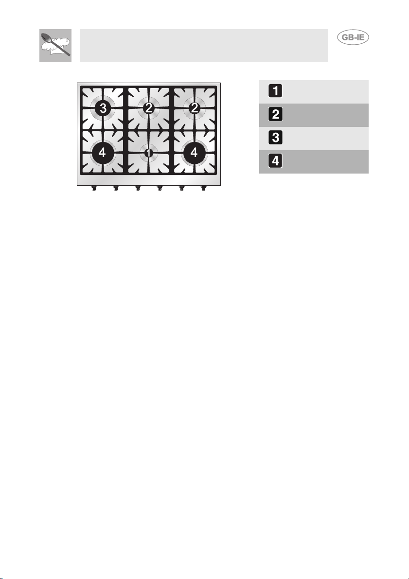
4. KNOW YOUR APPLIANCE
Auxiliary Burner
(AUX)
Semi-rapid Burner
(SR)
Rapid
Burner (R)
Ultra-rapid Burner
(URP)
7

Instructions for the User
5. USING THE HOB
5.1 Gas hob
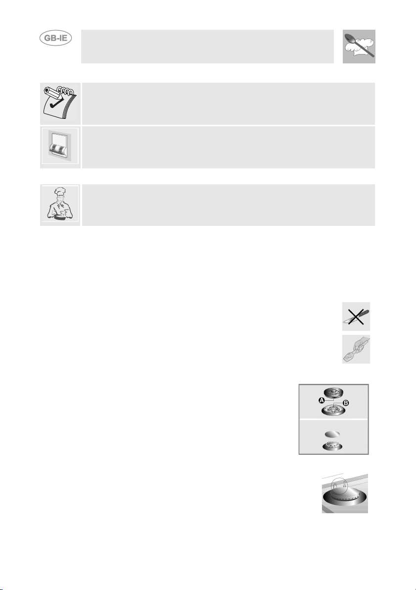
Before lighting the hob burners, check that the flame-spreader crowns are
correctly in place with their respective burner caps, making sure that the
holes A in the flame-spreaders are aligned with the plugs and
thermocouples.
Before using the electric plates or the barbecue (if included) for the first
time, pre-heat them to the maximum temperature long enough to burn off
any manufacturing oily residues which could give the food a bad smell.
The pan stand B is for use with woks. To prevent damage to the cooker
hob, it comes complete with a raised pan stand C. This must be placed
under pans with a diameter bigger than those indicated in the table in point
"5.3 Pan diameters". The pan stand C must never be used on the ultra-
rapid burner.
The burner controlled by each knob is shown next to
the knob. The appliance is equipped with an
electrical ignition device. Simply press the knob and
turn it counterclockwise to the maximum flame
symbol, until the burner lights. If it does not light in
the first 15 seconds, position the knob on 0 and wait
at least 60 seconds before trying to light it again.
On valved models, once the burner is lit, keep the knob pressed for a few
seconds to give the thermocouple time to heat up. The burner may go out
when the knob is released: in this case, the thermocouple has not heated
up sufficiently. Wait a few moments and repeat the operation keeping the
knob pressed for a longer time. This is not necessary on burners that are
not equipped with thermocouple. Once the burner is lit, the flame can be
adjusted as needed. Always check that the control knobs are in the (off)
position when you finish using the hob.
If the burners should go out accidentally, after about 20 seconds a safety
device will be tripped, cutting off the gas supply, even if the gas tap is
open. In this case, turn the knob to the OFF position and wait at least 60
seconds before trying to light the burner again.
8
Instructions for the User
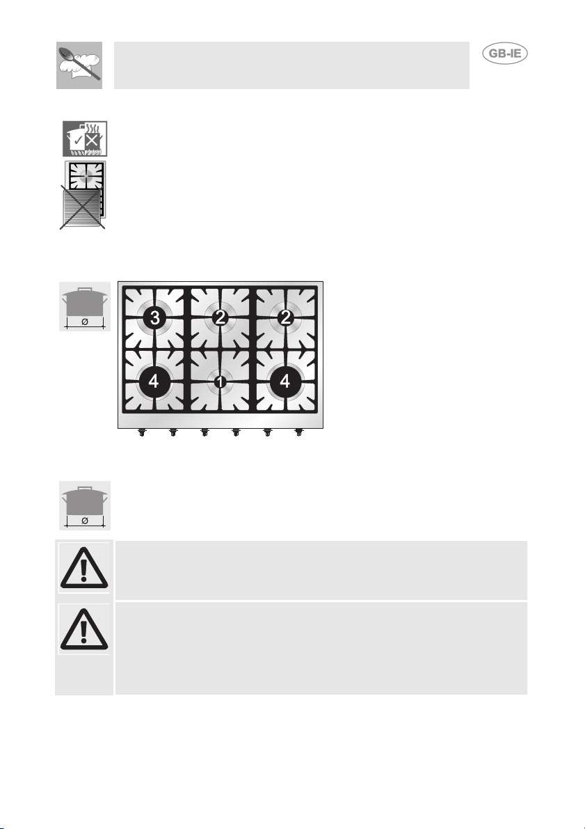
5.2 Practical tips for using the burners
For better burner efficiency and to minimise gas consumption, use pans
with a flat, smooth base and a lid that have a suitable size for the burner,
thus avoiding that the flames reach the sides of the pan (see point "5.3
Pan diameters"). Once the contents come to the boil, turn down the flame
far enough to prevent the liquid from boiling over.
To prevent burns or damage to the hob during cooking, all pans or griddle
plates must be placed inside the perimeter of the hob.
Take the greatest care when using fats or oils since they may catch fire if
overheated.
5.3 Pan diameters
BURNERS
MIN. AND MAX.
Ø (IN CM)
1 Auxiliary 2 Semi rapid 3Rapid 4 Ultra-rapid
12 - 14
16 - 20
18 - 24
20 - 26
The following are the diameters of the pans that can be used with the
raised pan stand:
BURNERS
1 Auxiliary 2 Rapid
MIN. AND MAX. Ø (IN CM)
16 - 24
26 - 28
If you have the Tepanyaki plate (optional extra) never use it on the ultrarapid burner for any reason.
Warning:
At the end of cooking using pans with aluminium bases you may find white
residues on the cast iron pan stands. These residues are usually caused
by the pan base rubbing against the pan stand and are difficult to remove
with normal cleaning. Using abrasive or excessively aggressive products
to clean the pan stand could damage its enamel surface.
9
Instructions for the User
6. CLEANING AND MAINTENANCE
NEVER USE A JET OF STEAM FOR CLEANING THE APPLIANCE.
Before performing any operations requiring access to powered
parts, switch off the power supply to the appliance.
6.1 Cleaning stainless steel
To keep stainless steel in good condition it should be cleaned regularly
after use. Let it cool first.
6.1.1 Ordinary daily cleaning
To clean and preserve the stainless steel surfaces, use only specific
products that do not contain abrasives or chlorine-based acids.
How to use: pour the product onto a damp cloth and wipe the surface,
rinse thoroughly and dry with a soft cloth or deerskin.
6.1.2 Food stains or residues
Do not use metallic sponges or sharp scrapers: they will
damage the surface. Use ordinary non-abrasive products for
steel, with the aid of wooden or plastic utensils if necessary.
Rinse thoroughly and dry with a soft cloth or deerskin.
10
6.2 Cleaning the gas components
For easier cleaning the pan stands, burner caps,
flame spreader crowns and burners can all be
removed; wash them with warm water and a nonabrasive detergent making sure to remove any
encrustation and wait until they are perfectly dry.
Replace the burner caps on their corresponding
crowns, making sure that the slots A are centred
with the burner pins B.
For correct operation the igniters and thermocouples must
always be perfectly clean. Check them frequently and
clean them with a damp cloth if necessary. Remove any dry
residues with a wooden toothpick or a needle.

Instructions for the installer
7. INSTALLING THE APPLIANCE
7.1 Positioning
This is a class 1 (B2) and 3 (A, B1)appliance.
The following operation requires building and/or carpentry work, therefore
it must be carried out by a skilled technician.
Installation can be carried out on various materials such as masonry,
metal, solid wood or plastic laminated wood as long as they are heat
resistant (T 90°C).
7.2 Heights for type A installation (empty base)
A
DISTANCES A B C L H
MINIMUM 866 mm 630 mm 50 mm 904 mm 750 mm
MAXIMUM 866 mm 650 mm - - -
The supporting strips must be of the appropriate size and secured
to the base in order to support the weight of the product and its use.
11

Instructions for the installer
7.3 Heights for type B installation (full base)
B
1
12
B
2
DISTANCES B C L H
MINIMUM 630 mm 50 mm 904 mm 750 mm
MAXIMUM 650 mm - - -

Instructions for the installer
681 mm
681 mm
355 mm
189.5 mm
96 mm 200 mm
434 mm
120 mm
83.5 mm
Ø 8 mm
Ø8mm
Ø8mm
Ø8mm
109. mm5
Z
83.5 mm
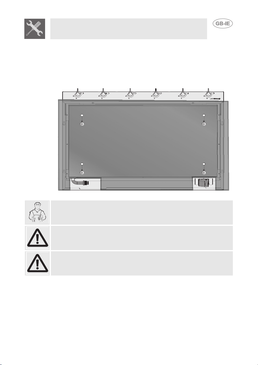
7.3.1 Supporting base
Make two openings in the rear part of the base as described in the figure
below. The left opening must be used for gas connections, and the right
one for electrical connections. Before securing the hob to the supporting
base, make 4 holes 8mm in diameter at the indicated points through
which the screws will pass that are to be secured into the rivets in the
bottom part of the product.
The interaxes of the holes and the dimensions of the openings refer to a
hob installed against the back wall.
13

Instructions for the installer
7.4 Mounting for type A installations
Once the hob is correctly positioned
in its support, place the brackets (A)
over the bottom part of the product
(B). Attachment requires 2 brackets
for each side of the hob.
1)
Secure the brackets to the walls of
the base by screwing the supplied
screws through the appropriate holes
(C). These operations will guarantee
that the entire product is mounted in
a stable way.
14
2)
Important: for fixing the product, use the supplied brackets in all the fixing
points.
Instructions for the installer
7.5 Mounting for type B installations
Once the hob is correctly positioned on the supporting base, complete
the mounting by tightening the product using the 4 supplied metric
screws, by screwing them through the 8mm Ø holes made before
installation. Make sure that the holes on the structure are centred with
those on the bottom of the product.
Important: other types of installation are possible if supervised by the
manufacturer.
Important: for fixing this product to the support structure, you are advised
not to use mechanical or electrical screwdrivers and to exert moderate
pressure by hand on the mounting parts.
If this product is installed over an oven, the oven must have a cooling fan.
15

Instructions for the installer
7.6 Electrical connection
Make sure that the voltage and capacity of the power line conform to the
data shown on the plate located under the casing.
Do not remove this plate for any reason.
The appliance must be connected to earth in compliance with electrical
system safety regulations.
If the appliance is connected to the power grid using a fixed connection, fit
the power line with an omnipolar circuit-breaker, in accordance with the
installation instructions, located in a readily accessible position near the
appliance.
If a plug and socket connection is being used make sure that the plug and
socket are compatible. Avoid use of adapters and shunts as these could
cause overheating and burns.
Operation at 220-240 V~: use an
H05V2V2-F type three-core cable
2
(3 x 0.75 mm
The end to be connected to the
appliance must be an earth wire
(yellow-green) at least 20 mm
longer.
The manufacturer declines all responsibility for damage to persons or
things caused by the non-observance of the above prescriptions or
deriving from tampering with any part of the appliance.
)
16

Instructions for the installer
7.7 Clearance above and around domestic appliances
Extract from AS5601
REQUIREMENTS
1 Overhead clearances – (Measurement A)
Range hoods and exhaust fans shall be installed in accordance with
the manufacturer’s instructions. However, in no case shall the
clearance between the highest part of the hob of the cooking appliance
and a range hood be less than 600 mm or, for an overhead exhaust
fan, 750 mm.
Any other downward facing combustible surface less than 600 mm
above the highest part of the hob shall be protected for the full width
and depth of the cooking surface area in accordance with Clause
5.12.1.2. However, in no case shall this clearance to any surface be
less than 450 mm.
17
Instructions for the installer
2 Side clearances – (Measurements B & C)
Where B, measured from the periphery of the nearest burner to any
vertical combustible surface, is less than 200 mm, the surface shall be
protected in accordance with Clause 5.12.1.2 to a height C of not less
than 150 mm above the hob for the full dimension (width or depth) of
the cooking surface area. Where the cooking appliance is fitted with a
‘splashback’, protection of the rear wall is not required.
3 Additional requirements for Freestanding and Elevated Cooking
Appliaces – (Measurements D & E)
Where D, the distance from the periphery of the nearest burner to a
horizontal combustible surface is less than 200 mm, then E shall be 10
mm or more, or the horizontal surface shall be above the trivet. See
insets above.
NOTES
1 Requirement 3 does not apply to a freestanding or elevated cooking
appliance which is designed to prevent flames or the cooking vessels
from extending beyond the periphery of the appliance.
2 The ‘cooking surface area’ is defined as that part of the appliance
where cooking normally takes place and does not include those parts
of the appliance containing control knobs.
3 For definition of hob, see Clause 1.4.64.
4 For definition of trivet, see Clause 1.4.109.
5 Consideration is to be given to window treatments when located near
cooking appliances. See Clause 5.3.4.
18

Instructions for the installer
8. GAS CONNECTION
This appliance is suitable for installation with
Natural Gas or ULPG (propane/butane). Refer
to page 12 for the relevant burner pressure and
appropriate injector sizes. When the appliance
is to be connected to Natural Gas then the
pressure regulator supplied must be fitted to the
gas inlet. A test point (for checking the gas
pressure) is supplied either with the regulator or
as a separate fitting in the case of ULPG
(propane/butane) appliances.
Connection of the appliance to the gas supply
must be in accordance with the requirements of
AS5601. A ½” BSP connector at the inlet is
recommended and the gas supply line to the
appliance must be of adequate length to allow
sufficient withdrawal of appliance for service or
disconnection and be:
1 annealed copper pipe or; 2 flexible hose according to AS/NZ1869 & be at least Class “B”, 10 mm
diameter.
The appliance must be installed with provision to allow the gas to be turned off and
disconnected for servicing and removal of the appliance as required from the gas
supply.
Before the appliance is operated make certain all relevant parts are placed in the
correct position.
When the installation is completed the installation connections of appliance will
require to be leak tested, the burner operating pressure and flame checked and
adjusted.
Warranty service calls do not cover these adjustments!
To check the operating pressure of the appliance it is recommended at least 2
large size burners are used. Ensure appliance is secured to wall when installation
is completed.
N.G. The regulator supplied must be fitted to the ½ BSP thread at the rear of the
appliance. An approved manual shut-off valve must be installed. The N.G.
regulator must be checked and adjusted to 1.0kPa after installation.
U.L.P.G.
directly. The pressure must be checked to
ensure it is operating at 2.75kPa. A separate
test point fitting must be installed between the
piping & the appliance for the pressure to be
checked to ensure it is operating at 2.75kPa.
Can be connected to the inlet fitting
19

Instructions for the installer
Installation with the flexible hose must be carried out so that the length of
the piping does not exceed 2 metres fully extended; make sure that the
hoses do not come into contact with moving parts and that they are not
crushed in any way.
8.1 Connection to liquid gas
Use a pressure regulator and make the connection on the gas cylinder
following the guidelines established by the regulations in force.
Make sure that the feed pressure complies with the values indicated in the
table at point “9.2 Burner and nozzle characteristics table”.
8.2 Room ventilation
Caution – This appliance may only be installed and operated in rooms
permanently ventilated in accordance with current regulations. For proper
operation of a gas appliance it is essential for the air necessary for
combustion of the gas to be able to flow naturally into the room. Air must
flow directly into the room through openings in its outside walls. This
(these) opening (s) must have a free passage cross-section of at least 100
cm2, or 200 cm2 for appliances not equipped with gas safety device.
These openings must be constructed so that they cannot be obstructed
indoors or outdoors, and should preferably be close to the floor on the side
opposite to the combustion gas discharge point. If it is not possible to
make the openings in the room where the cooker is installed, the
necessary air may be taken from an adjoining room, proveded it is not a
bedroom or a room with fire risk.
8.3 Combustion gas discharge
Combustion gases may be discharged by means of hoods connected to a
flue with reliable natural draught, or a fan extraction system. An effective
extraction system requires careful design by an authorised specialist, and
must comply with the regulation distances and positions. After installation,
the engineer must issue a certificate of compliance.
20

Instructions for the installer
9. ADAPTATION TO DIFFERENT TYPES OF GAS
Before carrying out the following operations, disconnect the appliance
from the electricity supply.
The appliance is preset for natural gas NG (2H) at a pressure of 1 kPa. In
the case of operation with other types of gas the burner nozzles must be
changed and the minimum flame adjusted on the gas taps. To change the
nozzles, proceed as described below.
9.1 Replacement of nozzles on the hob
1 Extract the pan stands and remove all the caps and flame-spreader
crowns;
2 Unscrew the burner nozzles with a 7 mm socket wrench;
3 Replace the burner nozzles according to the type of gas to be used
(see point “9.2 Burner and nozzle characteristics table“).
4 Replace the burners in the correct position.
21

Instructions for the installer
9.2 Burner and nozzle characteristics table
Burner ULPG - 2.75 kPa
Nominal gas
consumption
(MJ/h)
Auxiliary (1) 3.9 0.54
Semi rapid (2) 6.3 0.68
Rapid (3) 10.8 0.88
Ultra-rapid (4)
Burner NG - 1.0 kPa
Auxiliary (1) 3.9 0.90
Semi rapid (2) 7.5 1.20
Rapid (3) 12.0 1.55
Ultra-rapid (4)
13.5 1.00
Nominal gas
consumption
(MJ/h)
15.0 1.75
Injector
(mm)
Injector
(mm)
9.3 Arrangement of burners on cooking hob
BURNERS
1 Auxiliary 2 Semi rapid 3Rapid 4 Ultra-rapid
22

Instructions for the installer
10. FINAL OPERATIONS FOR GAS APPLIANCES
After making the adjustments described above, reassemble the appliance
by following the instructions in point "9.1 Replacement of nozzles on the
hob" in reverse order.
After adjustment with a gas other than the preset one, replace the label on
the casing of the appliance with the label corresponding to the new gas.
This label can be obtained from the nearest Authorised Service Centre.
10.1 Adjusting the minimum for natural gas
Light the burner and turn it to the minimum
position. Extract the gas tap knob and turn the
adjustment screw inside or next to the tap rod
(depending on the model) until the correct
minimum flame is achieved. Refit the knob and
verify that the burner flame is stable (turning the
knob rapidly from the maximum to the minimum
position the flame must not go out). Repeat the
operation on all the gas taps.
10.2 Adjusting the minimum for liquid gas
To adjust the minimum with liquid gas, you must tighten the screw inside
or next to the tap rod (depending on the model) fully in a clockwise
direction. The bypass diameters for each individual burner are shown in
the table "9.2 Burner and nozzle characteristics table".
10.3 Lubrication of gas taps
Over time the gas taps may become difficult to turn and get blocked. Clean
them internally and replace the lubrication grease. This operation must
be carried out by a specialised technician.
23


914773280/ A
 Loading...