

Contents
3
We advise you to read t his manual carefully . It contains all neces sary instructions for
and test the
use, a
1. Precautions for safety and use _________________________ 4
2. Instructions for disposal – our enviromental care ___________ 5
3. Safety instructions __________________________________ 6
4. Fitting the appliance in the top _________________________ 7
4.1 Fixing to the supporting structure ________________________________________ 7
4.2 Fitting the adhesive foam rubber strip _____________________________________ 8
4.3 Fitting the fixing clips __________________________________________________ 8
4.4 Fitting the hob into the hole in the work-top _________________________________ 8
5. Electrical connection _________________________________ 9
5.1 Clearances above and around domestic appliances _________________________10
6. Gas connection ____________________________________ 12
6.1 Connection to liquid gas ______________________________________________12
6.2 Room ventilation ____________________________________________________12
6.3 Combustion gas discharge ____________________________________________12
7. Adapting to different types of gas ______________________ 13
7.1 Removing the hob skin _______________________________________________13
7.2 Burner and nozzle characteristics table ___________________________________14
7.3 Hob burner layout ___________________________________________________14
7.4 Adjusting the primary air flow ___________________________________________14
7.5 Reassembling the hob skin ____________________________________________15
7.6 Adjusting the minimum setting for natural gas ______________________________15
7.7 Adjusting the minimum setting for liquid gas _______________________________15
7.8 Greasing the gas taps ________________________________________________15
8. De scr iption of controls ______________________________ 16
8.1 The front panel ______________________________________________________16
9. Using the hob _____________________________________ 17
9.1 Fitting the pan stands ________________________________________________17
9.2 Lighting burners with safety device ______________________________________20
9.3 Practical hints for using the burners _____________________________________20
9.4 Pan diameters ______________________________________________________20
10. Cleaning and maintenance _________________________ 21
10.1 Cleaning the hob ____________________________________________________21
10.2 Cleaning instructions for an acid-etched glass hob __________________________21
10.3 Cleaning the components _____________________________________________21
Thank you for choosing our product.
maintaining unaltered the appearance and functional qualities of the cooking hob.
INSTRUCTIONS FOR THE INSTALLER: these are intended for the authorized
person w ho is to check the gas supp ly system and install, commiss ion
appliance.
INSTRUCTIONS FOR THE USER: these provide recommendations for
description of the con t rols and the c orr ec t proc edures for cleanin g and maintaini ng t h e
appliance.
Precautions for Safety and Use
4
THIS MANUAL IS AN INTEGRAL PART OF THE APPLIANCE. TAKE GOOD CARE OF IT AND KEEP IT
O READ THIS MANUAL
KEEP THE SET OF
ED OUT BY QUALIFIED
DO NOT USE THIS APPLIANCE FOR HEATING ROOMS
DO NOT DISCARD PACKING IN THE HOME ENVIRONMENT. SEPARATE THE VARIOUS WASTE
WHEN DISPOSING OF THE APPLIANCE I T MUST BE TAKEN TO A SELECTIVE WAS TE CO LLECT IO N
DO NOT OBSTRUCT VENTILATION OPENINGS AND HEAT DISPERSAL SLITS.
DO NOT MODIFY THI S APPLIANCE.
DO NOT USE OR STORE FLAMMABLE MATERIALS IN THE APPLIANCE STORAGE DRAWER OR
THIS APPLIANCE IS DESIGNED FOR COOKING FOOD AND IT SHALL NOT BE USED AS A SPACE
DO NOT SPRAY AEROSOLS IN T H E VIC INITY OF THIS A PPL I ANCE WHILE IT IS IN OP E R ATION.
THE IDENTIFICATION PLATE, WITH THE TECHNICAL DATA, SERIAL NUMBER AND MARK IS IN A
1. Precautions for safety and use
TO HAND THROUGHOUT THE HOB'S LIFE CYCLE. USERS ARE ADVISED T
AND A LL THE INSTRUCTIONS IT CONTAINS BEFORE USING THE HOB. ALSO
NOZZLES PROVIDED IN A SAFE PLACE. INSTALLATION MUST BE CARRI
STAFF IN COMPLIANCE W ITH THE RELEVANT REGULATIONS. THIS APPLIANCE IS INTENDED FOR
HOUSEHOLD USE AND COMPLIES WITH THE EEC DIRECTIVES CURRENTLY IN FORCE. THE
APPLIANCE IS BUILT TO PROVIDE THE FOLLOWING FUNCTION: COOKING AND HEATING FOODS;
ALL OTHER USES ARE TO BE C O N SID ERED IMPROPER.
THE MANUFACTURER DECLINES ALL LIABILITY FOR USES OTHER THAN THOSE STATED ABOVE.
MATERIALS AND TAKE THEM TO THE NEAREST SELECTIVE WASTE COLLECTION CENTRE.
CENTRE.
NEAR THIS APPLIAN CE.
HEATER.
VISIBLE POSITIO N UN D ER THE CASING.
THE DUPLICATE DATA PLATE MUST BE ATTACHED TO AN ADJACENT SURFACE.
BEFORE CONNECTING THE DEVICE, MAKE SURE THAT IT HAS BEEN REGULATED FOR THE TYPE
OF GAS THAT WILL FEED IT, CHECKING THE LABEL UNDER THE CASING.
ALL SERVICING AND MAINTENANCE ARE TO BE COMPLETED BY THE MANUFACTURER’S
AUTHORISED PERSONNEL ONLY.

Instructions for disposal
5
Our product's packing is made of non-pollut ing materials, therefor e c ompatible with the
rectly. Find the
disposal centres from your retailer or from the
suffocat ion hazar d
the collec tion of
means intelligent recycling of
it along with the plug.
2. Instructions for disposal – our enviromental care
environme nt and recycl able. Please help by dispos ing of the packing cor
addresses of collection, recycling and
competent local organisations.
Do not thr ow the pack ing or any par t of it away . Th ey c an cons tit ute a
for children, especially the plastic bags.
Your old applian c e al so ne ed s t o b e di spos ed of co rrec tly.
Important : hand over your app liance to the loca l agency authoris ed for
household appliances no longer in use. Correct disposal
valuable materials.
It is also necessary to cut the intercon necting c able to the power suppl y net work, remo ving
Safety instructions
6
REFER TO THE INSTALLATION I NSTRUCTI ONS FOR THE SAFETY REGULATIONS FOR ELECTRIC
BY LAW THAT THE
OUT BY
SUITABLY SKILLED
IT IS OBLIGATORY FOR ALL ELECTRICAL SYSTEMS TO BE GROUNDED ACCORDING TO THE
THE PLUG TO BE CONNECTED TO THE POWER SUPPLY CABLE AND ITS SOCKET MUST BE OF
IMMEDIATELY AFTER INSTALLATION, CARRY OUT A QUICK TEST ON THE HOB FOLLOWING THE
FAILS TO OPERATE,
AFTER EACH USE OF THE HOB, ALWAYS CHECK THAT THE CONTROL KNOBS ARE TURNED TO
NEVER PLACE PANS WITH BOTTOMS WHICH ARE NOT PERFECTLY FLAT AND SMOOTH ON THE
NEVER USE PANS OR GRIDDLE PLATES WHICH PROJECT BEYOND THE OUTSIDE EDGE OF THE
THE APPLIANCE BECOMES VERY HOT DURING USE. SUITABLE HEATPROOF GLOVES SHOULD BE
THE USE OF THIS APPLIANCE IS NOT PERMITTED TO PEOPLE (INCLUDING CHILDREN) OF
HE USE OF
CTED BY ADULTS OR
WHERE THIS APPLIANCE IS INSTALLED IN MARINE CRAFT OR IN CARAVANS, IT SHALL NOT BE
The manufacturer declines all responsibility for injury or damage caused by failure to comply
iving from tampering with even just one part of the appliance
3. Safety instructions
OR GAS APPLIANCES AND VENTILATION FUNCTIONS.
IN YOUR INTERESTS AND FOR YOUR SAFETY IT HAS BEEN ESTABLISHED
INSTALLATION AND SERVICING OF ALL ELECTRICAL APPLIANCES IS TO BE CARRIED
QUALIFIED PERSONNEL IN ACCORDANCE WITH THE REGULATIONS IN FORCE.
OUR REGULAR INSTALLERS GUARANTEE A SATISFACTORY JOB.
GAS OR ELECTRIC APPLIANCES MUST ALWAYS BE DISCONNECTED BY
PEOPLE.
METHODS REQUIRED BY SAFETY RULES.
THE SAME TYPE AN D CONFORM TO THE REGULATIONS IN FORCE.
THE SOCKET MUST BE ACC ESSIBLE AFTER TH E APPLIANCE IS BUILT IN.
NEVER UNPLUG BY PULLING ON THE CABLE.
INSTRUCTIONS PROVIDED LATER IN THIS MANUAL. IF THE APPLIANCE
DISCONNECT IT FROM THE ELECTRICAL MAINS AND CONTACT YOUR NEAREST SERVICE
CENTRE.
NEVER ATTEMPT TO REPAIR THE APPLIANCE YOURSELF.
"ZERO" (OFF).
HOB PAN STANDS.
HOB.
WORN FOR ALL OPERATIONS.
REDUCED PHYSICAL AND MENTAL ABILITY, OR LACKING IN EXPERIENCE IN T
ELECTRICAL APPLIANCES, UNLESS THEY ARE SUPERVISED OR INSTRU
PEOPLE RESPONSIBLE FOR TH EIR SAFETY.
USED AS A SPACE HEATER.
with the above regulations or der
and the use of non-origin al sp ar e parts.
Instructions for the Installer
7
e of gas different from the one for which it
is preset in the factory, make this adjusting before building it into the unit,
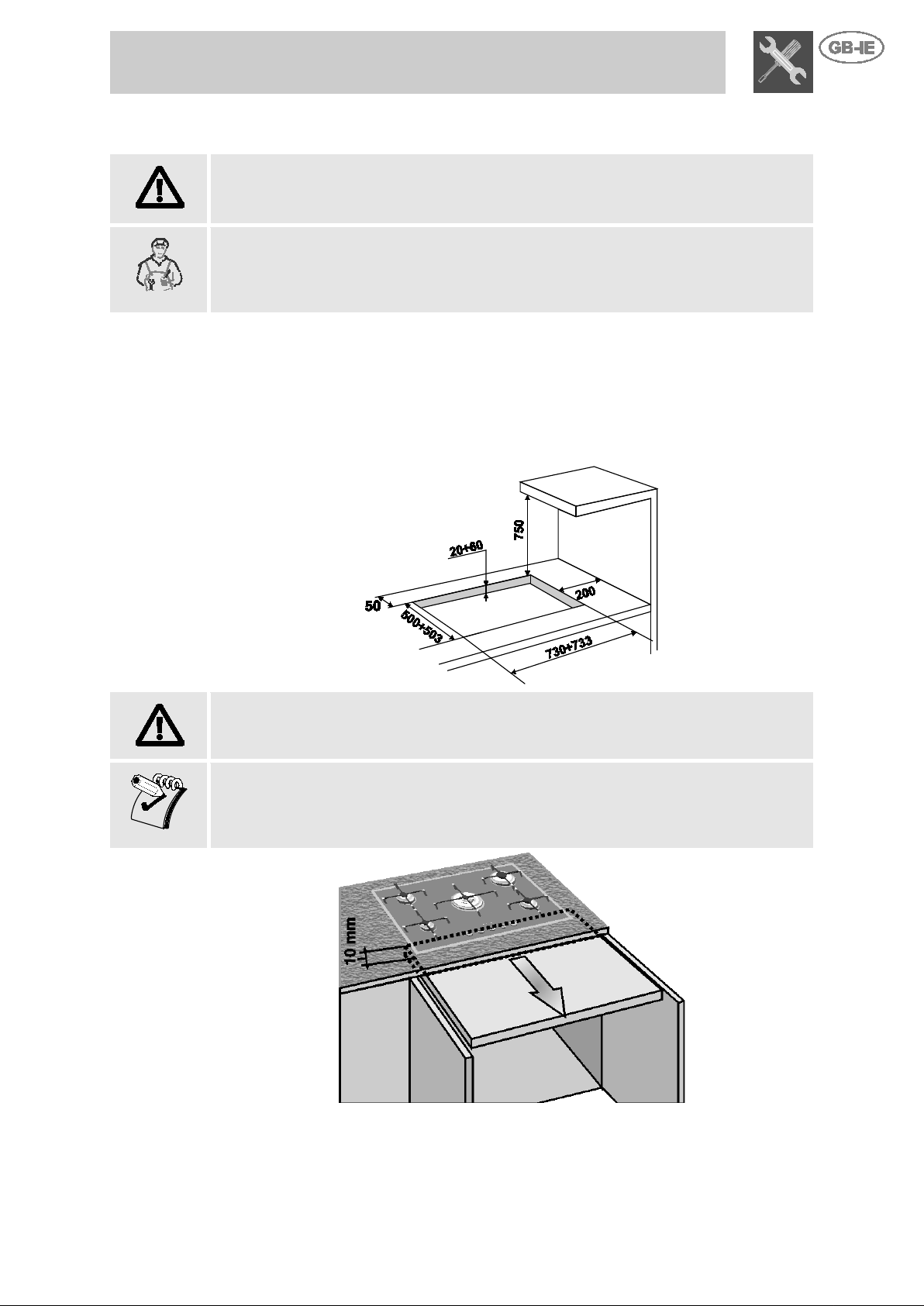
The hob can be installed o n various materials, including maso nry, metal, solid wood
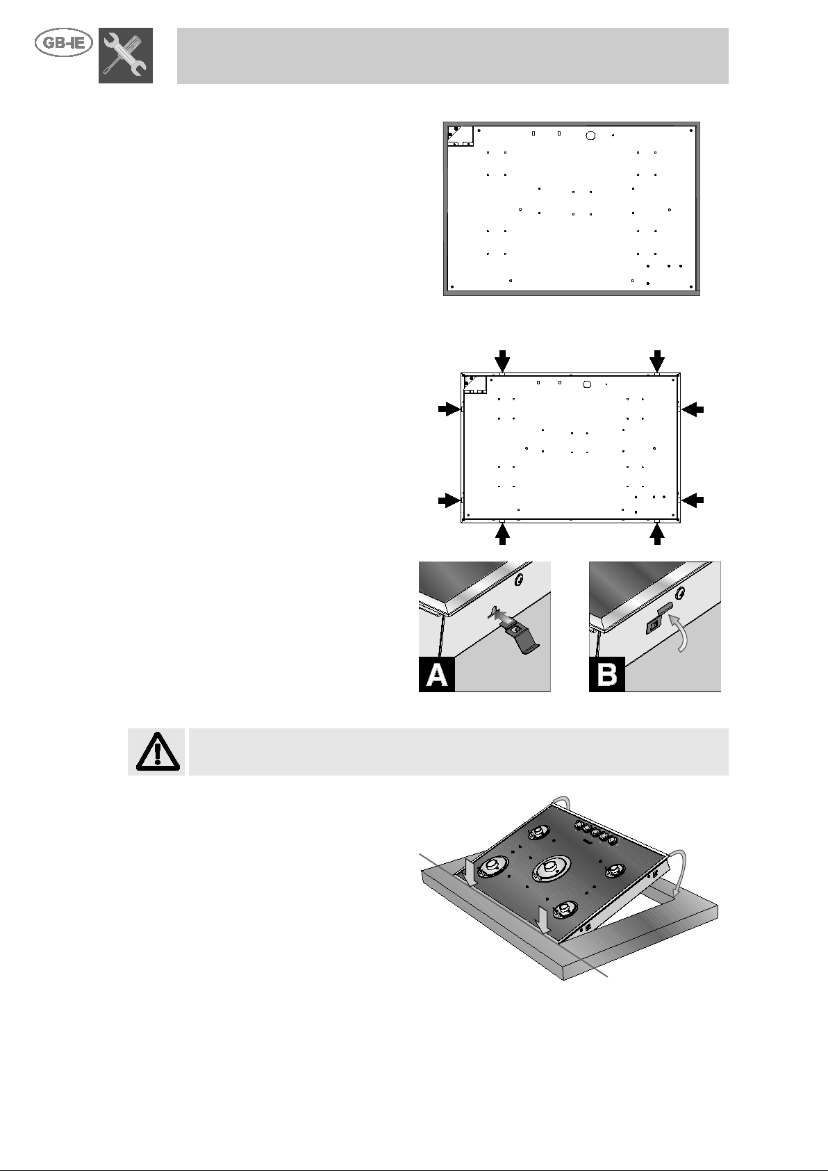
Make a hole in the cabinet top with the dimensions shown here, maintaining a
above them.
If the hob is installed above a cupboard with doors, a separator panel must be
installed underneath it. Le ave a gap of at le ast 10 mm betwe en the bottom of the hob
e of the panel, which must be easily removable to allow sufficient
4. Fitting the appliance in the top
If the hob has to be adapted for a typ
following the instructions in point “5. Adapting to different types of gas”.
The procedures required below must be carried out by a skilled builder and/or joiner.
and wood finished with plastic laminates, provided the material is heat-resistant
(T 90° C).
4.1 Fixing to the supporting structure
distance of at least 50 mm from the rear edge. This appliance may be installed
against walls higher than the worktop surface, provided the distance shown here is
maintained, in order to prevent damage due to overheating. Make sure that there is at
least 750 mm between the hob burners and a shelf or hood (if any) placed vertically
If the hob is installed above an oven, the oven must be fitted with a cooling fan.
and the surfac
access for any servicing procedures.
8
Fit the adhesive foam ru bber strip
(supplied with the h ob) aro und the
It will act as a cushion between
the surface of the surround and
that of the cabinet. The diagram
on the right shows the correct
m rubber strip.
Take great care when fitting it to
it does not project
beyond the outside edge of the
frame.
fixing cl ips in all th e points
marked with an arrow. The clips
fix the hob an ensure that it is
To fit the clips t o the hob, simply
press them gently horizont ally into
Then turn them upwards to fix
Before fitting the hob, remove
the pan stands (if fitted) and the
When fitting the hob, f irst rest the
round entirely on the back
top.
Do not apply leverage to the
surround; since this part is very
delicate there is a risk of
Then lower the front of the hob
until the appliance is completely in
place.
Instructions for the Installer
4.2 Fitting the adhesive foam rubber strip
outside edge of its surround.
position for the foa
ensure that
4.3 Fitting the fixing clips
Fit the
centred correctly.
the groove provided (fig. A).
them permanently in place (fig. B).
4.4 Fitting the hob into the hole in the work-top
Take special care when fitting the hob into the work-top. If the procedures are not
carried out correctly, exactly as described, the hob may be damaged.
burners from the hob.
sur
edge of the hole in the work-
damaging it.

Instructions for the Installer
9
Check that the po wer supply line voltage an d size are as specified on th e nameplate
The plug on the end of th e power supply lead and t he wall sock et must be of the same
type and comply with the relevant regulations. Check that the power supply line is
properly earthed.
Pass the power supply cab le throug h the rear of the c abinet, taking c are tha t it does not
If the appliance is connec ted to the power grid using a fixed c onnection, fit the power
breaker, in accordance with the installation instructions,
The use of reductions, adapters or junctions is not recommended.
the wires in the new cable must
must be at least 2 0 mm longer at th e end for conn ection to t he applia nce. Use only a type
mperature of up to 90°C. Th e cable must be
The manufacturer decl ines all responsibility for injury or damage caused by f ailure to
comply with the abov e regulations or deriving from tamper ing with even jus t one part
5. Electrical con nection
underneath the appliance's casing. This nameplate must never be removed.
touch the bottom case of the hob, or the oven (if any) built in underneath it.
line with an omnipolar circuitlocated in a readily accessible position near the appliance.
If the power supply cable has to be replaced, the gauge of
be at least 0.75 mm2 ( 3 x 0.75 cable), b earing in mind that the earth wire (y ellow-green)
H05V2V2-F or similar cable resist ant to a te
replaced by a q ualified electrici an, w ho mu st m a ke th e mai n s conn e ction a s s hown bel ow .
L = brown
N = blue
= yellow-green
The power supply lead mus t be repl ac ed by an a uthorised service centr e to pr eve nt al l
risks.
of the appliance.

10
1. Overhead clearances – (Measurement A)
and depth of the
5.12.1.2. However, in no
2. Side clearances – (Measurements B & C)
protected in
the cooking surfac e
‘splashback’, protect ion of
3. Additional requirements for Freestanding and Elevated Cooking
or more, or the horizontal surface shall be above the trivet. See insets above.
Instructions for the Installer
5.1 Clearances above and around domestic appliances
Extract from AS5601
REQUIREMENTS
Range hoods and exhaust fans shall be installed in accordance with the
manufacturer’s instruc t ions . How ev er , i n no cas e s ha ll the clearance betw e en
the highest part of the hob of the cooking appliance and a range hood be less
than 600 mm or, for an overhead exhaust fan, 750 mm.
Any other downward facing combustible s urfac e les s t han 60 0 mm above the
highest part of the h ob shall be protected for t he full width
cooking surface area in accordance with Clause
case shall this clearance to any surface be less than 450 mm.
Where B, measur ed from the periphery of the nearest burn er to any vertical
combustible surface, is less than 200 mm, the s urface shall be
accordance with Clause 5.12.1.2 to a height C of not less than 150 mm
above the hob for the fu ll dimension (width or de pth) of
area. Where the cook ing appliance is f itted with a
the rear wall is not required.
Appliaces – (Measurements D & E)
Where D, the distance from the periphery of the nearest burner to a
horizontal combustib le surface is less than 200 mm, then E sha ll be 10 mm

Instructions for the Installer
11
NOTES
1. Requirement 3 does not ap ply to a freestanding or ele v ated cook i ng appliance
from extending
of the
appliances. See Clause 5.3.4.
which is designed to prevent flames or the cooking vessels
beyond the periphery of the appliance.
2. The ‘cooking surface area’ is defined as that part of the appliance
3. where cooking norma lly takes place and does not include those parts
appliance containing control knobs.
4. For definition of hob, see Clause 1.4.64.
5. For definition of trivet, see Clause 1.4.109.
6. Consideration is to be give n to wind ow treatm ents wh en locat ed near cooking

12
This appliance is suitable for installation with Natural Gas or
to page 12 for the relevant
appropriate injector sizes. When the
pressure) is suppl ied either with the regul ator
must be in
AS5601. A ½” BSP
recommended and the gas supply line
withdrawal of appliance for service or disconnection and be:
1. annealed copper pipe or;
2. flexible hose according to AS/NZ1869 & be at least Class “B”, 10 mm diameter.
The appliance must be installed with provision to allow the gas to be turned off and
ted make certai n all relevant parts are placed in
When the installation is completed the installation connections of
require to be leak tested, the burner operating pressure and flame
large size burners
N.G. The
appliance. An
regulator must be checked
and adjusted to 1.0kPa after installation.
U.L.P.G. Can be conn ected to the inlet fi tting directly. T he
ensure it is operating at
test point fitting must be installed
the piping
hoses do not come into
Use a press ure regulator and make the connection on the gas cylinder f ollowing the
Make sure that the feed pressure
table at point “9.2 Burner and nozzle
characteristics table”.
Caution – This hob may only be installed and operated in rooms permanently
operation of a gas
appliance it is ess ential for the air necess ary for combustion of th e gas to be able to
section of at
least 100 cm2, or 200 cm2 for applia nces not e quipped w ith gas s afety dev ice. Thes e
openings must be constr ucted so that t hey cannot be obs tructed indoors or out doors,
site to the combus tion gas
discharge point. If it is not possible to make the openings in the room where the
cooker is installed, t he necess ary air may be taken from a n adjoinin g room, pro veded
it is not a bedroom or a room with fire risk.
Combustion gases may be discharged by means of hoods connected to a flue with
careful des ign by an authori sed spec ialist , and mus t comply with t he regul ation d istances
Instructions for the Installer
6. Gas connection
ULPG (propane/butane). Refer
burner pressure and
appliance is to be c onnected to Natural Gas then the pressure
regulator supplied must be fitted to the gas inlet. A test point (for
checking the gas
or as a separate fitting in t he case of ULPG (propane/butane)
appliances.
Connection of the appliance to the gas supply
accordance with the requirements of
connector at the inlet is
to the appl iance must be of adequ ate length to allow sufficient
disconnected for servicing and removal of the appliance as required from the gas
supply. Before the applian ce is opera
the c orrect position.
appliance will
checked and adjusted. Warranty ser v ice c alls do n ot cover these adjus tme nts ! To check
the operating pressur e of the appliance it is recommended at least 2
are used. Ensure appliance is secured to wall when installation is completed.
regulator supplied mus t be fitted to the ½ BSP thr ead at the rear of the
approved manual shu t-off valve mus t be installed . The N.G.
pressure must be checked to
2.75kPa. A separate
between the p iping & the appliance f or the pressure to b e
checked to ensure it is operating at 2.75kPa.
Installation with the flexible hose must be carried out so that the length of
does not exceed 2 metres fully extended; make sure that the
contact with moving parts and that they are not crushed in any way.
6.1 Connection to liquid gas
guidelines establis hed by the regulations in force.
complies with the values indicated in the
6.2 Room ventilation
ventilated in accordance with current regulations. For proper
flow naturally into the ro om. Air must flow direc tly i nto t he r oo m thr ou gh ope nin gs in its
outside walls. This (t hese) opening (s) must h ave a free passage cross -
and should preferab ly be c lose to t he floor on the s ide oppo
6.3 Combustion gas discharge
reliable natur al draught, or a fan extraction system. An effective extraction system r equires
and positions. Afte r installa tion, the enginee r must i ssue a cer tificat e of compl iance.

Instructions for the Installer
13
Lift all the burner
1
of each burner by
2
Remove the hob skin
ve the
screws shown on the
3
After removing all the
components described
above, lift off the hob
4
7. Adapting to different types of gas
The operations described below must be carried out with the appliance not
built-in and not connected to the gas or electricity supply.
The appliance is tested with NG (2H) natural gas at the pressure of 1 kPa.
If it is to be used with other types of gas, the burner nozzles have to be changed
and the primary air flow adjusted.
To replace the nozzles and adjust the burners, the hob skin has to be removed.
Proceed as described below.
7.1 Removing the hob skin
Remove all the burner components in the numerical order shown below:
• Pull off all the knobs.
•
components off the hob.
• Remove the cover plate
undoing the screws.
•
fixing screws, taking car e
only to remo
right.
•
skin.

14
Nominal gas consumption
(MJ/h)
Injector
(mm)
Auxiliary
4.1
0.54
Semi rapid
6.0
0.67
Rapid
10.4
0.85
Ultra Rapid
15.1
1.05
Nominal gas consumption
(MJ/h)
Injector
(mm)
Auxiliary
4.7
0.98
Semi rapid
6.1
1.10
Rapid
10.8
1.45
Ultra Rapid
14.6
1.70
Burner type
ULPG
2.75 kPa
Natural Gas
1.0 kPa
Auxiliary
9.5
2
Semi rapid
1
2
Rapid
3
3
Ultra Rapid
open
5
Instructions for the Installer
7.2 Burner and nozzle characteristics table
Burner ULPG – 2.75 kPa
Burner Natural Gas – 1.0 kPa
7.3 Hob burner layout
7.4 Adjusting the primary air flow
Refers to the gap “X” in mm.
BURNER
1 Auxiliary
2 Semi rapid
3 Rapid
4 Ultra rapid
To identify the burners on your hob, refer to the drawings in point “7.3 Hob burner
layout”.

Instructions for the Installer
15
Fit the pan stands as described in point 9.1Fitting the pan stands.
Reassemble the compone nts on the b urner and fit t he
Remove the knob again and adjust the regulator
on the
Put the knob back in place and c heck the stability of
the burner flame (the fla me must not go out when the
knob is turned quickly from the maximum to the
Use a pressure regulator and make the connection on the gas cylinder fol lowing the
e that the feed pressure complies with the values indicated in the table at
Over time, the gas taps m ay bec ome stiff or jam. Cle an their i nsides and change their
7.5 Reassembling the hob skin
Reverse the procedure described in point “7.1 Removing the hob skin”.
When replacing the cover plates, check that the seals are fitted correctly.
7.6 Adjusting the minimum setting for natural gas
knobs onto the tap rods.
Light the burner and turn it to the minimum setting.
screw inside or beside the tap rod (depending
model) until an even minimum flame is obtained.
minimum setting).
7.7 Adjusting the minimum setting for liquid gas
guidelines established by the regulations in force.
Make sur
point “7.2 Burner and nozzle characteristics table”.
7.8 Greasing the gas taps
lubricating grease. This operation must be carried out by a skilled technician.

16
5 Burner Hob
KNOB OPERATING MODE
clockwise to
Instructions for the User
8. Description of controls
8.1 The front panel
All the hob's control and monitoring devices are placed together on the front panel.
CONTROL AREA
To light the flame, press th e knob and at the same t ime turn it antithe minimum flame symbol .
To adjust the flame, turn t h e knob t o t he z one betw ee n the m ax im um and the
minimum settings.
To turn off the burner, turn the knob back to the O position.
BURNER LAYOUT - Key to symbols
Front left-hand burner
Rear right-hand burner
Rear left-hand burner
Front right-hand burner
Middle burner

Instructions for the User
17
Do not place anything, e.g.
flame tamer, asbestos mat,
between pan and pan
to the appliance may result.
Do not remove the pan
support and enclose the
this will concentrate and
deflect heat onto the hotplate.
Do not use large pots or heav y
weights which can bend the
, the
burners, the flame diffuser rings and the pan
e diffuser rings
in the burner.
in the burner must mate with the
The pan stands are supplied dis mantled from the ho b. To place each pan stan d on its
9. Using the hob
supports as serious damage
Check that the fixing cover plates E
stands are fitted correctly.
The projections A on the flam
must be fitted i nto the rece ss es B
The holes C
ignition plugs and thermocouples D on the hob.
9.1 Fitting the pan stands
burner with a wok stand as
pan support or deflect flame
onto the hotplate.
burner correctly, follow the instructions provided below:

Instructions for the User
18
should rest on top of it.
WRONG
RIGHT
Each rack must be position ed on the cor responding burner in
order to guarantee proper operation.
Be very careful to match the different central diameters of the
racks to the flame-spreader crowns.
At the ends of the legs of the racks ther e are
silicone rests wit h a hole t hat must be cent red
onto the matching fixing pins on the hob.
Make sure that the pan stands are simply fi tted over their burners, and are not
left in a raised or tilted position; if this occurs, repeat the fitting procedure.
To position the rack, you first need to centre
the fastening pins (1) and (2) and then lower it
until it is resting on the hob.
When properly positione d, the legs of the racks
must not be suspended above the hob but

Instructions for the User
19
WRONG
RIGHT
After performing the oper ations described above (for each pan stand), the hob will be
as shown below, with the feet of the pan stands for ming a pattern of horizontal and
vertical lines .
If a pan wobbles noticeably, check tha t th e pan stands have not been fitted
incorrectly.

Instructions for the User
20
The burner it controls is shown next to eac h knob (the exampl e here shows the fr ont
appliance is equip ped with electronic ignition. Simply press the knob and t urn it
e knob
pressed down for about 2 seconds to keep the flame alight and prime the safety
device. The burner may go out when the knob is released. In this case, repeat the
ol knob will ligh t up to confirm th at it is in oper ation.
e burner
goes out accidentally. The knob light comes on and goes out gradually.
If the burners should go out accidentally the safety device will be tripped about 20
For better burner efficienc y and to m in imis e gas cons u mpti on, us e f lat,
When cooking, to prevent burns or damage to the hob all pans or
BURNERS
min. and max.
k or heat
food.
9.2 Lighting burners with safety device
left-hand burner).
The
anti-clockwise to the mini mum flame symbol , until the burner lig hts. Keep th
operation, keeping the knob pressed down for longer.
When the burner has lit, its contr
The knob will go out a f ew seconds after it is tur ned to the O position, or if t h
seconds later, cutting off the gas supply even if the gas tap is open.
9.3 Practical hints for using the burners
even -bottomed pans wit h l i ds of s uit abl e s ize for t he b ur ner ( s ee po int
"9.4 Pan Diameters").
griddle plates must be placed inside the perimeter of the hob and must
be at least 5-7 cm from the knobs.
9.4 Pan diameters
1 Auxiliary
2 Semi rapid
3 Rapid
4 Ultra Rapid
Ø
(in cm)
7-18
10-24
18-24
20-28
• Do not use griddles or plates to cook or heat food on the ultra-
rapid/triple crown burner;
• Do not place aluminium foil under the burners during use;
• It is not advisable to use earthenware or steatite pans to coo

Instructions for the User
21
Never use metal scouring pads or sharp scrapers which will damage the
10. Cleaning and maint e nance
Before carrying out any operations, disc o nn ect the appliance from the
electricity supply.
Never use a jet of steam for cleaning the appliance.
10.1 Cleaning the hob
To keep the hob in good condition, it must be cleaned regularly, after each use, first
allowing it to cool.
10.1.1 Routine daily glass hob cleaning
When cleaning and car ing for glas s surfaces alway s use only specific products which
do not contain abrasives or chlorine-based acids.
Instructions for use: pour the product onto a da mp cloth and wipe ov er the surfac e,
then rinse thoroughly and dry with a soft cloth or chamois leather.
10.1.2 Food stains or spills
surface.
Use ordinary non-abrasive products for glass, with the aid of nonscratching sponges and wooden or plastic utensils if necessary.
Rinse thoroughly and dry with a soft cloth or chamois leather.
10.2 Cleaning instructions for an acid-etched glass hob
10.2.1 Grease
Use washing up liquid and a microfibre cloth.
10.2.2 Rings and encrustations
Use stainless steel cream or mildly a brasive creams ; leave the pro duct to act for a few
minutes, then wipe away with a microfibre cloth.
10.2.3 Stubborn encrustati o ns
If using the microf ibre cloth is not enough, a brass wire sponge can be used together
with stainless steel cream or standard abrasive creams available in shops.
To avoid encrustations which are difficult to remove, you are advised to clean
the hob every time you finish cooking.
10.3 Cleaning the components
Never clean the knobs with aggressive products containing alcohol or steel or glass
cleaners, since they might cause permanent damage.
NEVER REMOVE THE FIXING COVER PLATES TO CLEAN THE HOB.
The components described below must never be washed in a dishwasher.

Instructions for the User
22
The knobs must be cleaned with a soft cloth dipped in warm water and dried
thoroughly. They can easily be lifted off.
Remove the pan stands an d wash th em in warm wate r with a non -abras ive deter gent,
The burner caps and fl ame diffuser rings can be removed f or easier cleaning; wash
abrasive detergent, tak ing care to r emove all dep osits, and
in the flame diffuser ring. The
in the flame diffuse r ring must mate w ith t he ig nition plugs and thermoc ouples
D on the hob.
For best performance, the ignition plugs and thermocouples must always be kept
thoroughly clean. Check them fr equent ly and if neces sary clean them w ith a wet cloth.
914773752/ G
10.3.1 The knobs
10.3.2 The pan stands
taking care to remov e all d eposits. Rep lace the m on the h ob follow ing the i nstructions
provided in point “
10.3.3 The flame diffuser rings
them in hot water and nonwait for them to dry completely.
The burner pins A must be fitted into the recesses B
holes C
10.3.4 The plugs and thermocouples
Remove any dry residues with a wooden toothpick or a needle.
9.1Fitting the pan stands”.
 Loading...