

Contents
1. INSTRUCTIONS FOR USE ................................................................ 4
2. SAFETY PRECAUTIONS ................................................................... 6
3. ENVIRONMENTAL RESPONSIBILITY............................................... 8
4. USING THE HOB................................................................................ 9
5. CLEANING AND MAINTENANCE.................................................... 12
6. POSITION NEAR THE COUNTER TOP .......................................... 15
7. ADAPTATION TO DIFFERENT TYPES OF GAS ............................ 24
8. FINAL OPERATIONS ....................................................................... 26
THESE INSTRUCTIONS ARE VALID ONLY FOR THE DESTINATION COUNTRIES
WHOSE IDENTIFYING SYMBOLS ARE INCLUDED ON THE COVER OF THIS MANUAL.
INSTRUCTIONS FOR THE USER: these instructions contain user
recommendations, a description of the controls and the correct
procedures for cleaning and maintenance of the appliance.
INSTRUCTIONS FOR THE INSTALLER: these are intended for the
authorized person who must install the appliance, set it functioning and
carry out an inspection test.
3

General instructions
1. INSTRUCTIONS FOR USE
THIS MANUAL CONSTITUTES AN INTEGRAL PART OF THE APPLIANCE. THIS
MANUAL CONSTITUTES AN INTEGRAL PART OF THE APPLIANCE. IT SHOULD BE
KEPT INTACT AND AT HAND FOR THE APPLIANCE’S ENTIRE LIFE CYCLE.
IT IS IMPORTANT TO CAREFULLY READ THIS MANUAL AND ALL THE
INSTRUCTIONS CONTAINED HEREIN BEFORE USING THE APPLIANCE.
INSTALLATION MUST BE CARRIED OUT BY AUTHORIZED PERSONNEL AND
COMPLY WITH THE REGULATIONS IN FORCE. THIS APPLIANCE IS SPECIFIED FOR
DOMESTIC USE, AND COMPLIES WITH THE EEC DIRECTIVES CURRENTLY IN
FORCE. THE APPLIANCE IS MANUFACTURED IN ORDER TO PERFORM THE
FOLLOWING FUNCTIONS: COOKING FOOD; IT IS CONSIDERED UNSUITABLE FOR
ANY OTHER USE.
THE MANUFACTURER CANNOT BE HELD RESPONSIBLE FOR USES OTHER THAN
THOSE INDICATED.
IF THE APPLIANCE IS INSTALLED ON BOATS OR IN CARAVANS, DO NOT USE IT AS
A ROOM HEATER.
UNSUITABLE IN MARINE CRAFT, CARAVANS OR MOBILE HOMES, UNLESS EACH
BURNER IS FITTED WITH A FLAME SAFEGUARD
NEVER USE THIS APPLIANCE TO HEAT YOUR ENVIRONMENT.
BEFORE OPERATING THE APPLIANCE, IT IS MANDATORY TO REMOVE ALL
PROTECTIVE FILM.
DO NOT USE STEEL SPONGES AND SHARP SCRAPERS AS THEY WILL
DAMAGE THE SURFACE.
USE NORMAL NON-ABRASIVE PRODUCTS, INCLUDING WOODEN OR
PLASTIC UTENSILS IF NECESSARY. RINSE THOROUGHLY AND DRY
USING A SOFT CLOTH OR A MICROFIBRE CLOTH.
DO NOT LEAVE THE APPLIANCE UNATTENDED DURING COOKING PROCESSES
WHERE FATS OR OILS COULD BE RELEASED.
FATS AND OILS MAY CATCH FIRE.
ALWAYS CHECK THAT THE CONTROL KNOBS ARE IN THE
WHEN YOU FINISH USING THE APPLIANCE
NEVER PLACE PANS WITH BOTTOMS WHICH ARE NOT PERFECTLY FLAT AND
SMOOTH ON THE COOKING HOB PAN STANDS.
O (OFF) POSITION
4
General instructions
NEVER USE PANS OR GRIDDLE PLATES WHICH PROJECT BEYOND THE OUTSIDE
EDGE OF THE HOB.
SUITABLE HEAT-PROOF GLOVES SHOULD BE WORN FOR ALL OPERATIONS.
DO NOT USE OR STORE FLAMMABLE MATERIALS IN THE APPLIANCE STORAGE
DRAWER OR NEAR THIS APPLIANCE.
THIS APPLIANCE IS DESIGNED FOR COOKING FOOD AND IT SHALL NOT BE USED
AS A SPACE HEATER.
IN CASE OF SERVICE, CONTACT YOUR NEAREST SERVICE AGENT DISTRIBUTOR
LISTED IN THE WARRANTY CARD
5
General instructions
2. SAFETY PRECAUTIONS
REFER TO THE INSTALLATION INSTRUCTIONS FOR THE SAFETY REGULATIONS
FOR ELECTRIC OR GAS APPLIANCES AND VENTILATION FUNCTIONS.
IN YOUR INTERESTS AND FOR YOUR SAFETY THE LAW REQUIRES THAT THE
INSTALLATION AND SERVICING OF ALL ELECTRICAL APPLIANCES IS CARRIED
OUT BY QUALIFIED PERSONNEL IN ACCORDANCE WITH THE REGULATIONS IN
FORCE.
OUR APPROVED INSTALLERS GUARANTEE A SATISFACTORY JOB.
GAS OR ELECTRICAL APPLIANCES MUST ALWAYS BE DISCONNECTED BY
SUITABLY SKILLED PEOPLE.
BEFORE CONNECTING THE APPLIANCE TO THE POWER GRID, CHECK THE DATA
ON THE PLATE AGAINST THE DATA FOR THE GRID ITSELF.
THE IDENTIFICATION PLATE CONTAINING THE TECHNICAL DATA, SERIAL NUMBER
AND BRAND NAME IS IN A VISIBLE POSITION UNDER THE CASING.
DO NOT REMOVE THIS PLATE ON THE CASING FOR ANY REASON.
BEFORE CONNECTING THE DEVICE, MAKE SURE THAT IT HAS BEEN REGULATED
FOR THE TYPE OF GAS THAT WILL FEED IT, CHECKING THE LABEL UNDER THE
CASING.
BEFORE CARRYING OUT INSTALLATION/MAINTENANCE WORK, MAKE SURE THAT
THE APPLIANCE IS NOT CONNECTED TO THE POWER GRID.
THE PLUG TO BE CONNECTED TO THE POWER SUPPLY CABLE AND ITS SOCKET
MUST BE OF THE SAME TYPE AND CONFORM TO THE REGULATIONS IN FORCE.
THE SOCKET MUST BE ACCESSIBLE AFTER THE APPLIANCE HAS BEEN BUILT IN.
NEVER DISCONNECT THE PLUG BY PULLING ON THE CABLE.
IF THE POWER SUPPLY CABLE IS DAMAGED, CONTACT THE TECHNICAL SUPPORT
SERVICE IMMEDIATELY AND THEY WILL REPLACE IT.
IT IS OBLIGATORY FOR ALL ELECTRICAL EQUIPMENT TO BE EARTHED
ACCORDING TO THE METHODS LAID DOWN BY SAFETY REGULATIONS.
IMMEDIATELY AFTER INSTALLATION, CARRY OUT A BRIEF INSPECTION TEST,
FOLLOWING THE INSTRUCTIONS BELOW. SHOULD THE APPLIANCE NOT
FUNCTION, DISCONNECT IT FROM THE ELECTRICITY SUPPLY AND CALL THE
NEAREST TECHNICAL SUPPORT CENTRE.
NEVER ATTEMPT TO REPAIR THE APPLIANCE.
DURING USE THE APPLIANCE BECOMES VERY HOT. MAKE SURE YOU DO NOT
TOUCH THE HEATING ELEMENTS.
THIS APPLIANCE MAY NOT BE USED BY PEOPLE (INCLUDING CHILDREN) OF
REDUCED PHYSICAL AND MENTAL CAPACITY, OR LACKING IN EXPERIENCE IN
THE USE OF ELECTRICAL APPLIANCES, UNLESS THEY ARE SUPERVISED OR
INSTRUCTED BY ADULTS RESPONSIBLE FOR THEIR SAFETY.
6
General instructions
DO NOT LET CHILDREN GO NEAR THE APPLIANCE WHEN IT IS IN OPERATION OR
PLAY WITH IT AT ANY TIME.
DO NOT INSERT POINTED METAL OBJECTS (CUTLERY OR UTENSILS) INTO THE
SLITS IN THE APPLIANCE.
DO NOT USE STEAM JETS FOR CLEANING THE APPLIANCE.
THE STEAM COULD REACH THE ELECTRONICS, DAMAGING THEM AND CAUSING
SHORT-CIRCUITS.
DO NOT MODIFY THIS APPLIANCE.
DO NOT SPRAY ANY SPRAY PRODUCTS NEAR THE ELECTRICAL APPLIANCE
WHILE IT IS IN OPERATION.
DO NOT USE SPRAY PRODUCTS WHILE THE PRODUCT IS STILL HOT.
The manufacturer cannot be held liable for damage to persons or things caused by
failure to observe the above instructions, by interference with any part of the
appliance or by the use of non-original spare parts.
7
Instructions for disposal
3. ENVIRONMENTAL RESPONSIBILITY
Our products packing is made of non-polluting materials, which are therefore
compatible with the environment and recyclable. Please help by disposing of the
packaging correctly. You can obtain the addresses of collection, recycling and
disposal centres from your retailer or from the competent local organisations.
Do not discard the packaging or any part of it, or leave it unattended. It can
constitute a suffocation hazard for children, especially the plastic bags.
Your old appliance also needs to be disposed of correctly.
Important: hand over your appliance to the local agency authorised for the
collection of electrical appliances no longer in use. Correct disposal enables
intelligent recovery of valuable materials.
Before disposing of your appliance it is important to remove doors and leave
shelves in the same position as for use, to ensure that children cannot
accidentally become trapped inside during play. It is also necessary to cut the
connecting cable to the power grid, removing it along with the plug.
8
Instructions for the user
4. USING THE HOB
4.1 Lighting the hob burners
Before lighting the hob burners, check that the flame-spreader crowns are
correctly in place with their respective burner caps, making sure that the holes A
in the flame-spreaders are aligned with the igniters and thermocouples.
The burner controlled by each knob is shown next to the knob.
The appliance is equipped with an electrical ignition device.
Simply press the knob and turn it anti-clockwise to the
maximum flame symbol , until the burner lights.
On valved models, once the burner is lit, keep the knob pressed for a few
seconds to give the thermocouple time to heat up. The burner may go out when
the knob is released: in this case, the thermocouple has not heated up
sufficiently.
Wait a few moments and repeat the operation keeping the knob pressed for
longer. This is not necessary on burners that are not equipped with a
thermocouple.
Once the burner is lit, the flame can be adjusted as required.
Always check that the control knobs are in the O (off) position when you finish
using the hob.
If the burners should go out accidentally, after about 20 seconds a safety device
will be tripped, cutting off the gas supply, even if the gas tap is open. Turn off the
control knob and wait at least 1 minute before trying to re-light the burner.
9
Instructions for the user
4.2 Practical tips for using the burners
For better burner efficiency and to minimise gas consumption, use pans with a
flat, smooth base and a lid that have a suitable size for the burner, thus
preventing the flames reaching the sides of the pan (see paragraph “4.3 Pan
Diameter”). Once the contents come to the boil, turn down the flame far enough
to prevent the liquid from boiling over.
To prevent burns or damage to the hob during cooking, all pans or griddles must
be placed inside the perimeter of the hob.
Take the greatest care when using fats or oils since they may catch fire if
overheated.
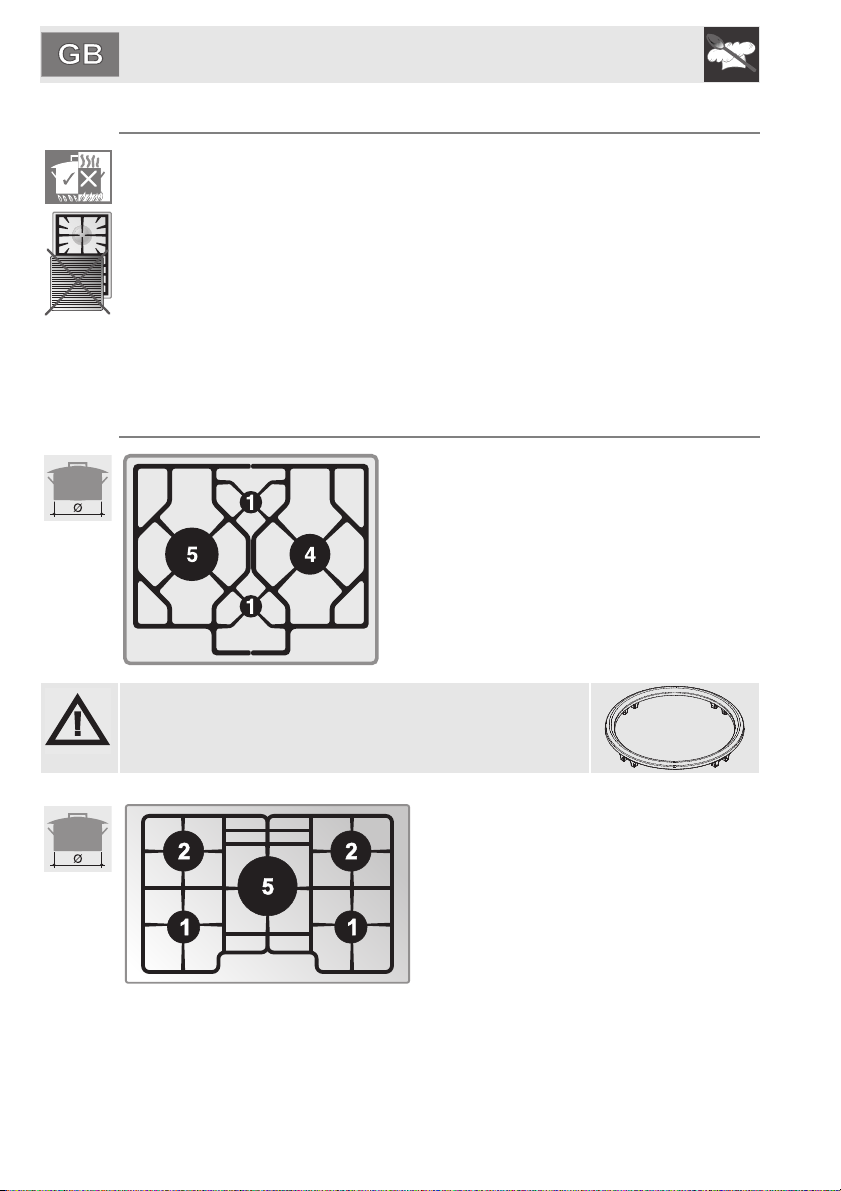
4.3 Pan diameters
HOB BURNER
1 Auxiliary
4 Rapid
5 Ultra-rapid
In this hob, the supplied reduced grill must only be
used for Chinese wok pans.
HOB BURNER
1 Auxiliary
2 Semi rapid
5 Ultra-rapid
The following are the diameters of the pans that can be used with the raised pan stand:
HOB BURNER
1 Auxiliary
2 Semi rapid
5 Ultra-rapid
Ø min. and max. (in cm)
Ø min. and max.
(in cm)
12 - 16
18 - 24
22 - 26
Ø min. and max.
(in cm)
12 - 16
16 - 22
20 - 26
16 - 26
22 - 26
26 - 34
10

Instructions for the user
3
1
HOB BURNER
1 Auxiliary
2 Semi rapid
5 Ultra-rapid
The following are the diameters of the pans that can be used with the raised pan stand:
HOB BURNER
1 Auxiliary
2 Semi rapid
5 Ultra-rapid
HOB BURNER
1 Auxiliary
3 Reduced rapid
6 Dual control
The following are the diameters of the pans that can be used with the raised pan stand:
HOB BURNER
1 Auxiliary
3 Reduced rapid
Ø min. and max. (in cm)
Ø min. and max. (in cm)
Ø min. and max.
(in cm)
12 - 20
16 - 24
20 - 26
16 - 26
22 - 26
26 - 34
Ø min. and max.
(in cm)
12 - 16
18 - 26
20 - 31
16 - 24
26 - 28
HOB BURNER
1 Auxiliary
3 Reduced rapid
HOB BURNER
1 Auxiliary
3 Reduced rapid
Ø min. and max. (in cm)
Ø min. and max.
(in cm)
12 - 16
18 - 26
16 - 24
26 - 28
11

Instructions for the user
5. CLEANING AND MAINTENANCE
Before performing any operations requiring access to powered parts,
switch off the power supply to the appliance.
NEVER USE A STEAM JET FOR CLEANING THE APPLIANCE.
5.1 Cleaning stainless steel
To keep stainless steel in good condition it should be cleaned regularly
after use. Let it cool first.
5.1.1 Ordinary daily cleaning
To clean and preserve the stainless steel surfaces, use only specific products
that do not contain abrasives or chlorine-based acids.
How to use: pour the product onto a damp cloth and wipe the surface, rinse
thoroughly and dry with a soft cloth or chamois leather.
5.1.2 Food stains or residues
Never use metallic sponges or sharp scrapers as they will damage the
surface.
Use ordinary non-abrasive products for steel, with the aid of wooden
or plastic utensils if necessary.
Rinse thoroughly and dry with a soft cloth or chamois leather.
12
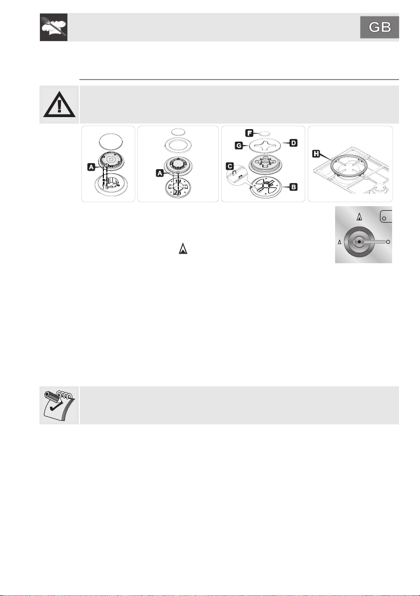
5.2 Cleaning the cooking hob parts
For easier cleaning the pan stands, burner caps, flame
spreader crowns and burners can all be removed; wash them
with warm water and a non-abrasive detergent making sure to
remove any encrustation, then wait until they are completely
dry. Replace the burner caps on their corresponding crowns,
making sure that the slots A are centred with the pins B on the
burners.
For correct operation, the igniters and thermocouples must
always be perfectly clean. Check them frequently and clean
them with a damp cloth if necessary. Remove any dry residues
with a wooden toothpick or a needle.

Instructions for the user
In models with central pan stand, fit this piece, taking care that its centre is
perfectly aligned with the centre of the burner
In models equipped with pan stands, fit as shown in the figure, taking care to
position them exactly as shown. Refer to the enlarged details in the figure below
for guidance.
13

Instructions for the user
5.3 Preventive Maintenance
This appliance does not need any special maintenance. However, a few simple
operations have to be carried out periodically to prevent malfunctioning;
Burners: the burners must be cleaned periodically to ensure correct conbustion
make sure that all the openings and flame ports are clean and free of obstacles,
and the burners rest firmly on their supports.
Gas connection: the gas connection must be checked periodically.
Flexible pipes: if a flexible pipe is used, it must be inspected periodically (once
a year) for leakages if the surface of the pipe appears rigid and cracked,
disconnect immediately the cooker from the gas supply and replace the pipe
with a new one.
Valves: if the gas valves get stuck or hard to turn, they need to be cleaned and
re-greased; this operation must be carried out by an authorised person.
5.4 Problems and causes
Each of the following cases is caused by an abhnormal operation of the
appliance and should be dealt with by an authorised person: please contact
your local dealer or Service Center in case you detect any of these
malfunctioning.
PROBLEM CAUSE WHAT TO DO
The flame is very long
with bright yellow .
Black deposits on the
bottom of the pans.
The flame is very short
and noisy. The flame
moves away from the
burner ports.
The flame extingulshes
when the burner knob is
set to the low flame
position.
The valve knob is hard to
rotate.
Defect of comburent air
or incorrect injectors.
Burner dirty or flame
ports obstructed.
Excess of comburent air. Call Service Center
Incorrect adjustment of
the minimum heat input
or excess of comburent
air.
Gas valve worn out or
needs lubrification.
Clean the burner.
Call Service Center if the
problem remains.
Call Service Center
Call Service Center
14

Instructions for the installer
6. POSITION NEAR THE COUNTER TOP
The following operation requires building and/or carpentry work so must be carried out by
a competent tradesman.
Installation can be carried out on various materials such as masonry, metal, solid wood or
plastic laminated wood as long as they are heat resistant (T 90°C).
6.1 Fixing to a support structure model with traditional casing (fig. 1)
Create an opening with the dimensions shown in the figure in the top surface of the
counter, keeping a minimum distance of 50 mm from the rear edge. This appliance can be
mounted against walls higher than the work surface on condition that a distance of "X" be
kept between the appliance and the wall as shown in the figure so as to avoid damage
from overheating. Make sure that there is a minimum of 750 mm between the gas rings
and any shelf that may be installed directly above them.
1)
Carefully position the supplied insulating seal on the outer edge of the hole on the top hob,
as indicated in figure 2. Try and make it stick to the whole surface by applying light hand
pressure. The front and back sides of the seal must be touching the hole.
complete flatness.
Trim any excess trimming from border A with care (Fig.3). The quotes in figure 2 are
references for the hole on the inside of the trimming. The small brackets in figure 4 are
only positioned after having mounted the hob.
(only 60 cm models)
2)
3)
Carry out this operation by supporting the hob on the isolating seal and using screws and
clamping brackets (Fig. 4) to fix the hob to the support structure, in order to obtain the
complete flatness.
4)
15

Instructions for the installer
494
292
510,8
310,8
73
3,3
PGA64
PGA75SC3
PGA95SC3
PSA906
16
(only “906” models)
PGA32

Instructions for the installer
6.2 Fixing to the electric model support structure
Create an opening with the dimensions shown in the figure in the top surface of
the counter, keeping a minimum distance of 50 mm from the rear edge.
The lower part of the casing must be fully accessible after the appliance has
been installed. This appliance can be mounted against walls higher than the
work surface on condition that a distance of "X" be kept between the appliance
and the wall as shown in the figure so as to avoid damage from overheating.
Make sure that there is a minimum of 750 mm between the hob ring flames and
any shelves placed directly above them (Fig. 1). Furthermore, this kind of
appliance needs a milling on the hob top of 3 mm in depth; the measurements
are indicated in figure 4 (detail A of figure 3).
1)
Before positioning the hob, the supplied adhesive sponge “E” should be spread
out flat over the milling surface (fig. 3). Carry out this operation by supporting the
hob on the isolating seal and using screws and clamping brackets (Fig. 2
sequence) to fix the hob to the support structure, in order to obtain the complete
flatness. The small brackets in figure 2 are only positioned after having
mounted the hob.
(only 60 cm models)
2)
17

Instructions for the installer
PGA64F
PGA75F3 - PGA75FSC3
PGA95F3 - PGA95FSC3
PSFA906
3)
18
4)
(only “906” models)
If laminated surfaces are used, it is advisable to spread a layer of anti-infiltration
“primer” across the milled surface.
Important: Other types of installation are possible if supervised by the
manufacturer!

Instructions for the installer
31,5
228
122
480
14,2
24,7
Obstructions: location of gas and electric connectors (measured in mm).
PGA64F
PGA95F3 - PGA95FSC3
PGA32
PGA75F3 - PGA75FSC3
PSFA906
Precautions: the temperature of the inside surface of the hob may exceed
125°C.
To avoid any hazardous situations, over-the-hob access must be restricted.
Refer to the installation instructions.
19

Instructions for the installer
IMPORTANT: if the appliance is mounted on a unit, make sure that a separating
shelf is installed, as shown in the figure.
However, if the appliance is on an oven installed under the hob, there is no need
to install a separating shelf.
If installed on top of an oven, the latter must be equipped with a cooling fan.
20

Instructions for the installer
6.3 Clearances above and around domestic appliances
Extract from AS5601
REQUIREMENTS
1 Overhead clearances – (Measurement A)
Range hoods and exhaust fans shall be installed in accordance with the
manufacturer’s instructions. However, in no case shall the clearance between the
highest part of the hob of the cooking appliance and a range hood be less than 600
mm or, for an overhead exhaust fan, 750 mm.
Any other downward facing combustible surface less than 600 mm above the highest
part of the hob shall be protected for the full width and depth of the cooking surface
area in accordance with Clause 5.12.1.2. However, in no case shall this clearance to
any surface be less than 450 mm.
2 Side clearances – (Measurements B & C)
Where B, measured from the periphery of the nearest burner to any vertical
combustible surface, is less than 200 mm, the surface shall be protected in
accordance with Clause 5.12.1.2 to a height C of not less than 150 mm above the
hob for the full dimension (width or depth) of the cooking surface area. Where the
cooking appliance is fitted with a ‘splashback’, protection of the rear wall is not
required.
3 Additional requirements for Freestanding and Elevated Cooking
Appliaces – (Measurements D & E)
Where D, the distance from the periphery of the nearest burner to a horizontal
combustible surface is less than 200 mm, then E shall be 10 mm or more, or the
horizontal surface shall be above the trivet. See insets above.
21

Instructions for the installer
NOTES
1 Requirement 3 does not apply to a freestanding or elevated cooking appliance which
is designed to prevent flames or the cooking vessels from extending beyond the
periphery of the appliance.
2 The ‘cooking surface area’ is defined as that part of the appliance
3 where cooking normally takes place and does not include those parts of the appliance
containing control knobs.
4 For definition of hob, see Clause 1.4.64.
5 For definition of trivet, see Clause 1.4.109.
6 Consideration is to be given to window treatments when located near cooking
appliances. See Clause 5.3.4.
6.4 Electrical connection
Make sure that the voltage and capacity of the power line conform to the data
shown on the plate located under the casing. Do not remove this plate for any
reason.
The plug at the end of the supply cable and the wall socket must be of the same
type and must conform to the applicable legislation on electrical installations.
Make sure that the supply line is suitably earthed.
Fit power line with an omnipolar circuit breaker with a contact opening gap equal
to or greater than 3 mm in an easily accessible position close to the hob.
22
Avoid the use of adapters and shunts.
If the power cable is replaced, the crosssection of wires in the new cable must be
no less than 0.75 mm2 (3 x 0.75 cable),
remembering that the end for connection to
the appliance must have a longer earth
wire (yellow/green)
, longer by at least 20 mm. Only use a H05V2V2-F or similar resistance cable to
the maximum temperature of 90°C. Its replacement must be carried out be a
specialised technician who must carry out the network connection following the
diagram below.
L = brown
N - blue
= yellow/green
The manufacturer cannot be held liable for damage to persons or things caused
by non-observance of the above directions or by interference with any part of the
appliance.

Instructions for the installer
6.5 Gas connection
This appliance is suitable for installation with
Natural Gas or ULPG (propane/butane). Refer to
page 25 for the relevant burner pressure and
appropriate injector sizes. When the appliance is
to be connected to Natural Gas then the pressure
regulator supplied must be fitted to the gas inlet.
A test point (for checking the gas pressure) is
supplied either with the regulator or as a separate
fitting in the case of ULPG (propane) appliances.
Connection of the appliance to the gas supply
must be in accordance with the requirements of
AS5601. A ½” BSP connector at the inlet is
recommended and the gas supply line to the
appliance must be of adequate length to allow
sufficient withdrawal of appliance for service or
disconnection and be:
1. annealed copper pipe or;
2. flexible hose according to AS/NZ1869 & be at least Class “B”, 10 mm
diameter.
The appliance must be installed with provision to allow the gas to be turned off
and disconnected for servicing and removal of the appliance as required from
the gas supply.
Before the appliance is operated make certain all relevant parts are placed in
the correct position.
On completion of the installation, the installer MUST check for gas leaks and
test each burner individually for the correct flame. Once all burners have been
tested individually, turn all burners on together.
Warranty service calls do not cover these adjustments!
To check the operating pressure of the appliance it is recommended at least 2
large size burners are used. Ensure appliance is secured to wall when
installation is completed.
N.G. The regulator supplied must be fitted to the ½ BSP thread at the rear of the
appliance. An approved manual shut-off valve must be installed. The N.G.
regulator must be checked and adjusted to 1.0kPa after installation.
U.L.P.G. Can be connected to the inlet fitting
directly. The pressure must be checked to ensure
it is operating at 2.75kPa. A separate test point
fitting must be installed between the piping & the
appliance for the pressure to be checked to
ensure it is operating at 2.75kPa.
23

Instructions for the installer
Installation with the flexible hose must be carried out so that the length of the
piping does not exceed 2 metres fully extended; make sure that the hoses do
not come into contact with moving parts and that they are not crushed in any
way.
6.6 Connection to liquid gas
Use a pressure regulator and make the connection on the gas cylinder following
the guidelines established by the regulations in force. Make sure that the feed
pressure complies with the values indicated in the table at point “9.2 Burner and
nozzle characteristics table”.
6.7 Room ventilation
Caution – This hob may only be installed and operated in rooms permanently
ventilated in accordance with current regulations. For proper operation of a gas
appliance it is essential for the air necessary for combustion of the gas to be
able to flow naturally into the room. Air must flow directly into the room through
openings in its outside walls. This (these) opening (s) must have a free passage
cross-section of at least 100 cm2, or 200 cm2 for appliances not equipped with
gas safety device. These openings must be constructed so that they cannot be
obstructed indoors or outdoors, and should preferably be close to the floor on
the side opposite to the combustion gas discharge point. If it is not possible to
make the openings in the room where the cooker is installed, the necessary air
may be taken from an adjoining room, proveded it is not a bedroom or a room
with fire risk.
24
6.8 Combustion gas discharge
Combustion gases may be discharged by means of hoods connected to a flue
with reliable natural draught, or a fan extraction system. An effective extraction
system requires careful design by an authorised specialist, and must comply
with the regulation distances and positions. After installation, the engineer must
issue a certificate of compliance.

Instructions for the installer
7. ADAPTATION TO DIFFERENT TYPES OF GAS
Before carrying out the following operations, disconnect the appliance from the
power supply.
The appliance is preset for natural gas NG at a pressure of 1.0 kPa. In the case
of operation with other types of gas, the burner nozzles must be changed and
the minimum flame adjusted on the gas taps. To change the nozzles, proceed
as described in the following paragraphs.
7.1 Replacement of the cooking hob nozzles
1 Extract the pan racks and remove all the caps and flame-spreader crowns;
2 Unscrew the burner nozzles with a 7 mm socket spanner;
3 Replace the burner nozzles according to the gas to be used (see paragraph
“7.2 Burner and nozzle characteristics table”);
4 Replace the burners in the correct position.
25

Instructions for the installer
7.2 Burner and nozzle characteristics table
Burner ULPG – 2.75 kPa
Nominal gas
Consumption (MJ/h)
Auxiliary (1) 3.9 0.54
Semi rapid (2) 6.3 0.68
Reduced rapid (3) 9.0 0.85
Rapid (4) 10.8 0.88
Ultra rapid (5) 15.0 1.05
Dual control (6)
Burner NG – 1.0 kPa
Consumption (MJ/h)
Auxiliary (1) 3.9 0.90
Semi rapid (2) 7.5 1.20
Reduced rapid (3) 9.0 1.40
Rapid (4) 12.0 1.55
Ultra rapid (5) 15.0 1.75
Dual control (6)
3.2
13.6
Nominal gas
3.6
15.0
Injector
(mm)
Centre 0.50
Outer 0.72 + 0.72
Injector
(mm)
Centre 0.85
Outer 1.26 + 1.26
26

Instructions for the installer
3
1
7.3 Arrangement of the burners on the cooking hob
HOB BURNER
1 Auxiliary
2 Semi rapid
3 Reduced Rapid
4 Rapid
5 Ultra-rapid
6 Dual control
27

Instructions for the installer
914773814/ C
8. FINAL OPERATIONS
After making the adjustments described above, reassemble the appliance by
following in reverse the instructions reported in paragraph "7.1 Replacement of
the cooking hob nozzles".
After adjustment with a gas other than the preset one, replace the label on the
casing of the appliance with the label corresponding to the new gas. This label
can be obtained from the nearest Authorised Service Centre.
8.1 Adjusting the minimum for town and natural gas
Light the burner and turn it to the
minimum position. Extract the gas tap
knob and turn the adjustment screw
inside or next to the tap rod (depending
on the model) until the correct
minimum flame is achieved.
Refit the knob and verify that the burner
flame is stable (when turning the knob
rapidly from the maximum to the
minimum position the flame must not
go out). Repeat the operation on all
the gas taps.
28
8.2 Adjusting the minimum setting for liquid gas
To adjust the minimum setting with liquid gas, you must tighten the screw inside
or next to the tap rod (depending on the model) fully in a clockwise direction.
The diameters of the by-passes for the individual burners are given in the
paragraph “7.2 Burner and nozzle characteristics tables".
8.3 Lubrication of gas taps
Over time the gas taps may become difficult to turn and get blocked. Clean them
internally and replace the lubrication grease. This procedure must be carried
out by a specialised technician.
 Loading...