

Page 1
EN - PAD / PAD1 DEMINERALISED WATER PUMP
1
WARNING
This instruction sheet is intended for authorised SMEG technical
personnel.
WARNING - WHEN INSTALLING THE “PAD” OR “PAD1” MAKE SURE THAT:
The pump intake pressure is less than 1 bar. SMEG is not liable for any damage if the
demineralised water pump is installed with higher intake pressures.
Warning: this component is powered at mains voltage:
~230V 50Hz 1/N/PE - grounding is required.
SMEG declines all responsibility for any damage or injury caused by incorrect installation
of the pump by unauthorised technical staff. Use only the fixing devices supplied by Smeg.
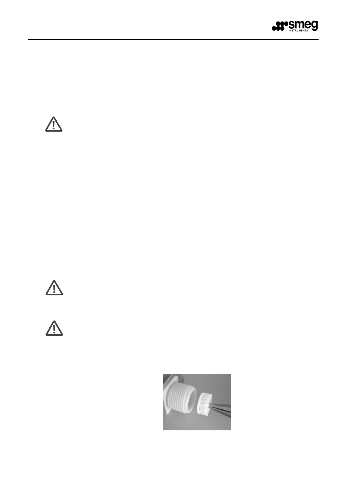
WARNING – DEMI WATER SOLENOID VALVE FLOW REDUCER
In some cases, if the water pressure is insufficient for proper operation of the solenoid
valve even with the pump installed, the flow reducer fitted inside the valve must be
removed as shown below.
1. Remove the valve’s external filter (white)
SMEG PAD-PAD1
INSTALLATION INSTRUCTION SHEET
DEMINERALISED WATER PUMP
1 CONTENTS OF THE PACK
1. 1 (one) pump support box; the steel box contains the assembled PAD pump.
2. 1 (one) power cord for electrical connection of the pump.
3. Mounting and sealing accessories (4 self-tapping screws for sheet metal, for fixing the box to the
rear casing, one gasket for connecting the water supply hose to the pump)
2 ATTENTION
SMEG appliances may not be connected to non-pressurised demineralised water supplies (e.g. tanks
operating by gravity) unless a special “PAD” demineralised water pump is installed.
This pump ensures that the demineralised water is supplied to the appliance with sufficient pressure to
ensure its proper operation. The PAD is installed on the outside of the rear of the appliance.
The PAD must be installed on the appliance by a SMEG authorised technician.
19 390 1994 08
Page 2
EN - PAD / PAD1 DEMINERALISED WATER PUMP
2
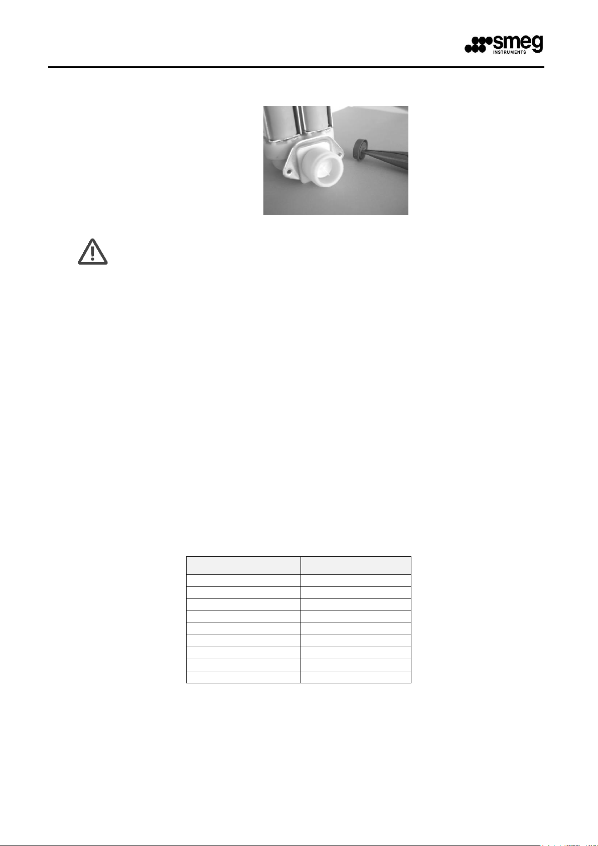
2. Remove the flow reducer underneath the filter, then put the filter back in place.
WARNING
Once the reducer has been removed, the valve is able to deliver a higher flow rate.
If the intake pressure increases due to changes in the upstream system, reassess
the operating conditions.
At high pressures, valves without flow reducers may malfunction and be unable to
shut off the flow effectively.
SERIES
COMPATIBILITY
GW2045
PAD1
GW1060
PAD
GW3060
PAD
GW4060
PAD1
GW4090
PAD
GW4190
PAD1
WD1050
PAD
WD4060
PAD1
WD4190
PAD1
3 COMPATIBILITY BETWEEN PAD AND SMEG APPLIANCE MODELS
Appliance models which can be fitted with the optional PAD demineralised water pump:
GW1060, WD1050, GW3060, GW4090.
4 COMPATIBILITY BETWEEN PAD1 AND SMEG APPLIANCE MODELS
Appliance models which can be fitted with the optional PAD1 demineralised water pump:
GW1160, WD1160, GW4060, WD4060, GW4190, WD4190.
The pump is connected to the electrical system in parallel with the “EVD” demineralised water solenoid
valve.
Some models are prewired for electrical connection of the PAD; the connection cable is inside the rear
casing. The relevant products are:
GW3060, GW4090.
Other models are not prewired and the PAD or PAD1 pump has to be connected in parallel with the EVD
demi water solenoid valve using the cable provided:
GW2045, GW1060, WD1050, GW1160, WD1160, GW4060, WD4060, GW4190, WD4190.
5 PAD INSTALLATION PROCEDURE
The procedure for installing the PAD pump is similar on different models; for the sake of brevity, only
installation on the SMEG WD1050 model is described in detail below.
Access to the rear of the appliance, and the rear cross-piece in particular, is required.
19 390 1994 08
Page 3
EN - PAD / PAD1 DEMINERALISED WATER PUMP
3
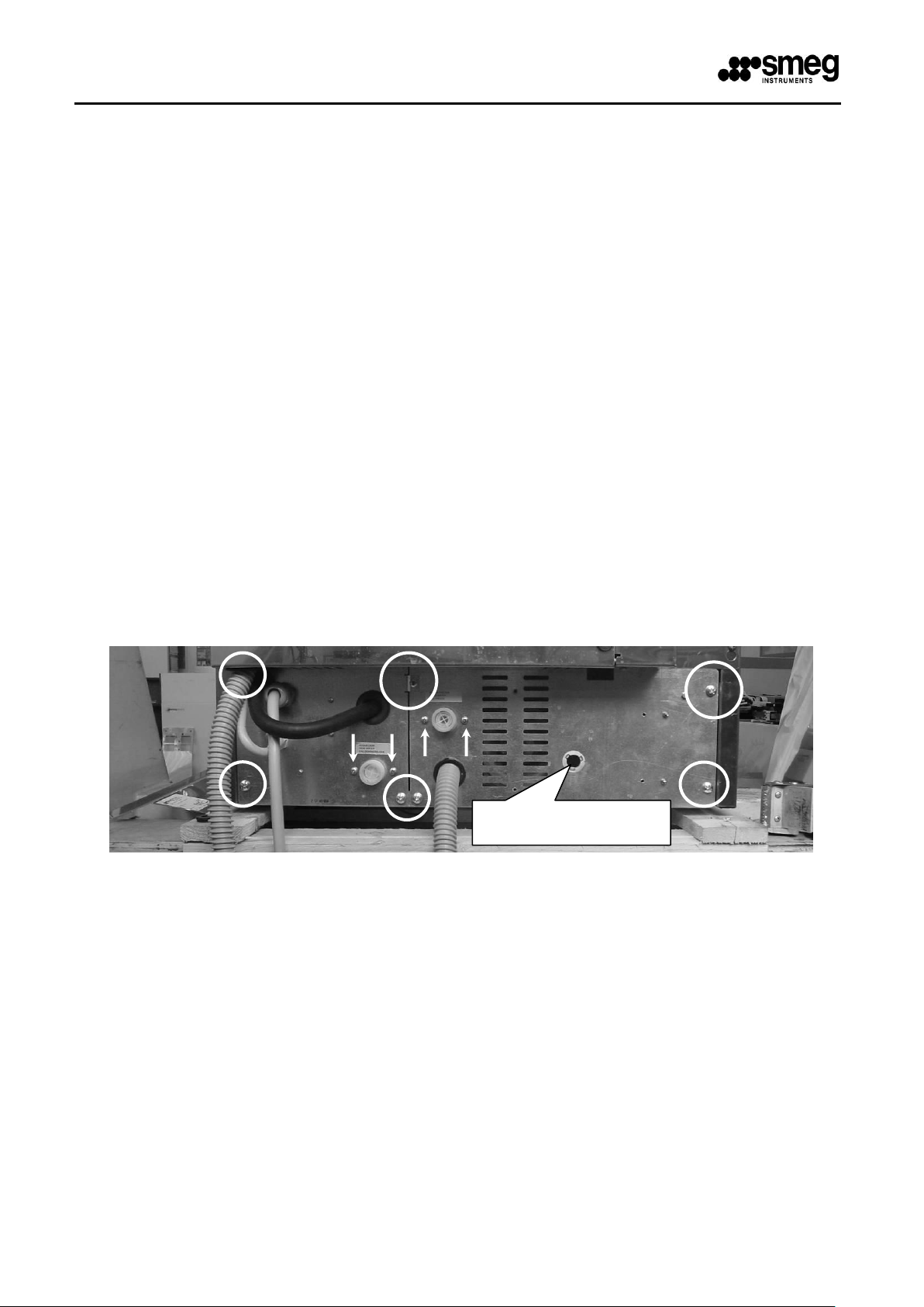
PAD POWER SUPPLY
CABLE ENTRY SLEEVE
The PAD comes complete with a cable for the electrical connection to the appliance.
The installation procedure is as follows:
a. Disconnect the water intake hoses from their respective solenoid valves:
b. Unscrew the fixing screws that secure the right and left lids to the rear cross-piece
and the solenoid fixing screws;
c. Pass the PAD connection cable supplied through the sleeve on the right-hand lid and
connect the end with “dual faston” terminal (insulated female faston terminal
combined with male terminal) to the demi water solenoid valve and the appliance’s
wiring system. This connects the PAD pump in parallel with the solenoid valve.
d. The yellow/green ground wire must be connected to the unused faston terminal fixed to the
brass screw on the plate on the right at the rear of the appliance (on the inside). The
appliance’s main ground line is connected to the brass screw;
e. Close the metal lids and secure the solenoid valves;
f. Make the electrical connection to the pump;
g. Fix the metal box containing the “PAD” to the plate on the rear of the appliance using the
self-tapping screws provided;
Reconnect the intake hoses. The demineralised water intake hose is a transparent mesh-
reinforced hose.
N.B.: on GW3060 and GW4090 models the connecting cable supplied with the pump is not required. There
is a terminal board to which the wiring for connection of the PAD is connected on the inside of the rear
casing.
Disconnect the wiring from the terminal board and use it to make the electrical connection to the PAD.
fig. 1 – Rear of the appliance showing the cross-piece lid and solenoid valve fixing points. The sleeve
through which the electrical connection cable is passed is on the right-hand lid.
19 390 1994 08
Page 4
EN - PAD / PAD1 DEMINERALISED WATER PUMP
4
CONNECT THE DUAL FASTON
TERMINALS OF THE CABLE SUPPLIED
TO THE DEMI WATER SOLENOID VALVE
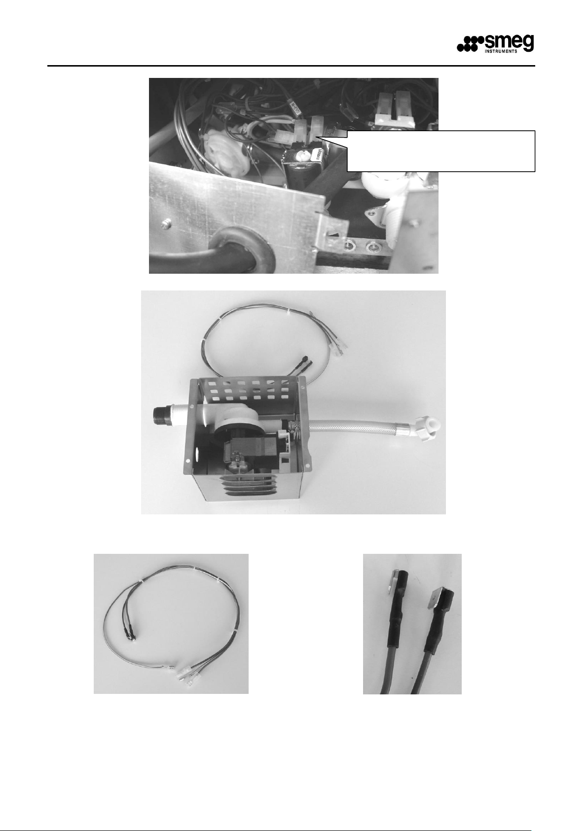
fig. 2 – Rear of the appliance showing the demi water solenoid valve.
fig. 3 – PAD accessory: pump intake port (for connection of the intake hose) on left, delivery port (for
fig. 4 – PAD accessory: connection cable supplied and detail of the dual faston terminals for parallel
connection of the PAD pump and the DEMI water solenoid valve.
19 390 1994 08
connection to the demi water solenoid valve) on right.
Page 5

EN - PAD / PAD1 DEMINERALISED WATER PUMP
5
“EVD” DEMI WATER
SOLENOID VALVE
PAD STEEL BOX
fig. 5 - tube with cap to vent air from the impeller.
6 PAD1 INSTALLATION PROCEDURE
The procedure for installing the PAD1 pump is similar on different models; for the sake of brevity, only
installation on the SMEG GW4060SC model is described in detail below.
19 390 1994 08
fig. 6 – PAD accessory, PAD mounting position on rear of WD1050 model.
Page 6

EN - PAD / PAD1 DEMINERALISED WATER PUMP
6
CONNECT THE DUAL FASTON
TERMINALS OF THE CABLE
SUPPLIED TO THE DEMI
WATER SOLENOID VALVE
CONNECT THE GROUND
FASTON TERMINAL TO THE
UNUSED MALE FASTON
TERMINAL
Access to the rear of the appliance, and the rear cross-piece in particular, is required.
The PAD1 comes complete with a cable for the electrical connection to the appliance.
The installation procedure is as follows:
a. Disconnect the water intake hoses from their respective solenoid valves:
b. Remove the rear of the appliance;
c. Unscrew the fixing screws that secure the left lid to the rear cross-piece;
d. Pass the PAD1 electrical connection cable supplied, complete with sleeve, through the hole
in the left-hand lid and connect the end with “dual faston” terminal (insulated female
faston terminal combined with male terminal) to the demi water solenoid valve and the
appliance’s wiring system. This connects the PAD pump in parallel with the solenoid
valve.
e. The yellow/green ground wire must be connected to the unused male faston terminal next to
the demi water solenoid valve;
f. Close the metal lid, taking care not to trap any of the appliance’s wiring;
g. Replace the rear of the appliance;
h. Fix the metal box containing the “PAD1” to the rear of the appliance using the self-tapping
screws provided;
Reconnect the intake hoses. The demineralised water intake hose is a transparent mesh-
reinforced hose.
fig. 7 – Rear of the appliance showing the points where the right-hand lid is fixed to the cross-piece; note the
hole through which the electrical connection cable, complete with sleeve, has to be passed.
fig. 8 – Rear of the appliance showing the demi water solenoid valve.
19 390 1994 08
Page 7

EN - PAD / PAD1 DEMINERALISED WATER PUMP
7
Inlet
Outlet
fig. 9 – PAD1 accessory: pump intake port (for connection of the intake hose) on left, delivery port (for
connection to the demi water solenoid valve) on right.
19 390 1994 08
Page 8

EN - PAD / PAD1 DEMINERALISED WATER PUMP
8
PAD STEEL BOX
“EVD” DEMI WATER
SOLENOID VALVE
PAD1 CABLE
FIXING POINT
fig. 10 – PAD accessory: connection cable, detail of the sleeve and the dual faston terminals for parallel
connection of the PAD1 pump and the DEMI water solenoid valve.
NB: The power supply cable can be fixed to the rear of the appliance as shown in fig. 11.
19 390 1994 08
fig. 11 – PAD1 accessory, PAD1 mounting position on GW4060SC model.
Page 9

EN - PAD / PAD1 DEMINERALISED WATER PUMP
9
PAD power cable
exit point;
Remove power
cable protection;
Remove the cap
from the stainlesssteel box and insert
the tube in the hole
then fix the nut by
using the tool;
7 MOUNTING PAD-PAD1 PUMP ON PREPARED MODELS
Pictures are referred to GW4060 model.
19 390 1994 08
Page 10

EN - PAD / PAD1 DEMINERALISED WATER PUMP
10
Fix wires on the
electrical
connectors of the
pump;
Fix the stainlesssteel box on the
machine backside
by using 4 screws;
Connect the PAD
output tube to demi
electric-valve;
19 390 1994 08
Page 11

EN - PAD / PAD1 DEMINERALISED WATER PUMP
11
Connect water inlet
hose to PAD pump
Outlet
Inlet
8 FUNCTIONAL DIAGRAM - PRESENCE OF PAD-PAD1 PUMP
fig. 5 – Water system diagram of WD1050 and GW4060SC, as modified by connection of the PAD or PAD1
accessory
19 390 1994 08
Page 12

EN - PAD / PAD1 DEMINERALISED WATER PUMP
12
08
13 / 01 / 2015
PAD1 instructions.
REV.
DATA
NOTE
9 DIMENSION ACCESSORY
19 390 1994 08
Smeg S.p.A.
Instruments Division
Via Leonardo da Vinci, 4
Tel +39 0522 8211 – Fax +39 0522 821 592
E-mail: instruments@smeg.it – service.instruments@smeg.it
www.smeg-instruments.com
 Loading...