

Contents
1. INSTRUCTIONS FOR USE....................................................... 4
2. SAFETY PRECAUTIONS.......................................................... 6
3. ENVIRONMENTAL RESPONSIBILITY ..................................... 8
4. DESCRIPTIONS OF THE CONTROLS .................................... 9
5. USING THE HOB .................................................................... 10
6. CLEANING AND MAINTENANCE .......................................... 11
7. POSITIONING OF THE HOB .................................................. 14
8. ADAPTATION TO DIFFERENT TYPES OF GAS ................... 20
9. FINAL OPERATIONS.............................................................. 23
THESE INSTRUCTIONS ARE VALID ONLY FOR THE DESTINATION COUNTRIES
WHOSE IDENTIFYING SYMBOLS ARE INCLUDED ON THE COVER OF THIS MANUAL.
INSTRUCTIONS FOR THE USER: these instructions contain user
recommendations, a description of the controls and the correct
procedures for cleaning and maintenance of the appliance.
INSTRUCTIONS FOR THE INSTALLER: these are intended for the
authorized person who must install the appliance, set it functioning and
carry out an inspection test.
3
General instructions
1. INSTRUCTIONS FOR USE
THIS MANUAL CONSTITUTES AN INTEGRAL PART OF THE APPLIANCE. THIS
MANUAL CONSTITUTES AN INTEGRAL PART OF THE APPLIANCE. IT SHOULD BE
KEPT INTACT AND AT HAND FOR THE APPLIANCE’S ENTIRE LIFE CYCLE.
IT IS IMPORTANT TO CAREFULLY READ THIS MANUAL AND ALL THE
INSTRUCTIONS CONTAINED HEREIN BEFORE USING THE APPLIANCE.
INSTALLATION MUST BE CARRIED OUT BY AUTHORIZED PERSONNEL AND
COMPLY WITH THE REGULATIONS IN FORCE. THIS APPLIANCE IS SPECIFIED FOR
DOMESTIC USE, AND COMPLIES WITH THE EEC DIRECTIVES CURRENTLY IN
FORCE. THE APPLIANCE IS MANUFACTURED IN ORDER TO PERFORM THE
FOLLOWING FUNCTIONS: COOKING FOOD; IT IS CONSIDERED UNSUITABLE FOR
ANY OTHER USE.
THE MANUFACTURER CANNOT BE HELD RESPONSIBLE FOR USES OTHER THAN
THOSE INDICATED.
WHERE THIS APPLIANCE IS INSTALLED IN MARINE CRAFTS OR IN CARAVANS, IT
SHALL NOT BE USED AS A SPACE HEATER
UNSUITABLE IN MARINE CRAFT, CARAVANS OR MOBILE HOMES, UNLESS EACH
BURNER IS FITTED WITH A FLAME SAFEGUARD
NEVER USE THIS APPLIANCE TO HEAT YOUR ENVIRONMENT.
BEFORE OPERATING THE APPLIANCE, IT IS MANDATORY TO REMOVE ALL
PROTECTIVE FILM.
DO NOT USE STEEL SPONGES AND SHARP SCRAPERS AS THEY WILL
DAMAGE THE SURFACE.
USE NORMAL NON-ABRASIVE PRODUCTS, INCLUDING WOODEN OR
PLASTIC UTENSILS IF NECESSARY. RINSE THOROUGHLY AND DRY
USING A SOFT CLOTH OR A MICROFIBRE CLOTH.
DO NOT LEAVE THE APPLIANCE UNATTENDED DURING COOKING PROCESSES
WHERE FATS OR OILS COULD BE RELEASED.
FATS AND OILS MAY CATCH FIRE.
ALWAYS CHECK THAT THE CONTROL KNOBS ARE IN THE
WHEN YOU FINISH USING THE APPLIANCE
NEVER PLACE PANS WITH BOTTOMS WHICH ARE NOT PERFECTLY FLAT AND
SMOOTH ON THE COOKING HOB PAN STANDS.
O (OFF) POSITION
4
General instructions
NEVER USE PANS OR GRIDDLE PLATES WHICH PROJECT BEYOND THE OUTSIDE
EDGE OF THE HOB.
SUITABLE HEAT-PROOF GLOVES SHOULD BE WORN FOR ALL OPERATIONS.
DO NOT USE OR STORE FLAMMABLE MATERIALS IN THE APPLIANCE STORAGE
DRAWER OR NEAR THIS APPLIANCE.
THIS APPLIANCE IS DESIGNED FOR COOKING FOOD AND IT SHALL NOT BE USED
AS A SPACE HEATER.
IN CASE OF SERVICE, CONTACT YOUR NEAREST SERVICE AGENT DISTRIBUTOR
LISTED IN THE WARRANTY CARD
5
General instructions
2. SAFETY PRECAUTIONS
REFER TO THE INSTALLATION INSTRUCTIONS FOR THE SAFETY REGULATIONS
FOR ELECTRIC OR GAS APPLIANCES AND VENTILATION FUNCTIONS.
IN YOUR INTERESTS AND FOR YOUR SAFETY THE LAW REQUIRES THAT THE
INSTALLATION AND SERVICING OF ALL ELECTRICAL APPLIANCES IS CARRIED
OUT BY QUALIFIED PERSONNEL IN ACCORDANCE WITH THE REGULATIONS IN
FORCE.
OUR APPROVED INSTALLERS GUARANTEE A SATISFACTORY JOB.
GAS OR ELECTRICAL APPLIANCES MUST ALWAYS BE DISCONNECTED BY
SUITABLY SKILLED PEOPLE.
BEFORE CONNECTING THE APPLIANCE TO THE POWER GRID, CHECK THE DATA
ON THE PLATE AGAINST THE DATA FOR THE GRID ITSELF.
THE APPLIANCE IS SUPPLIED WITH A DUPLICATE DATAPLATE, PLEASE ATTACH TO
AN ADJACENT SURFACE FOR FUTURE REFERENCE.
THE IDENTIFICATION PLATE CONTAINING THE TECHNICAL DATA, SERIAL NUMBER
AND BRAND NAME IS IN A VISIBLE POSITION UNDER THE CASING.
THE DUPLICATE MUST BE ATTACHED TO AN ADJACENT SURFACE.
BEFORE CONNECTING THE DEVICE, MAKE SURE THAT IT HAS BEEN REGULATED
FOR THE TYPE OF GAS THAT WILL FEED IT, CHECKING THE LABEL UNDER THE
CASING.
BEFORE CARRYING OUT INSTALLATION/MAINTENANCE WORK, MAKE SURE THAT
THE APPLIANCE IS NOT CONNECTED TO THE POWER GRID.
THE PLUG TO BE CONNECTED TO THE POWER SUPPLY CABLE AND ITS SOCKET
MUST BE OF THE SAME TYPE AND CONFORM TO THE REGULATIONS IN FORCE.
THE SOCKET MUST BE ACCESSIBLE AFTER THE APPLIANCE HAS BEEN BUILT IN.
NEVER DISCONNECT THE PLUG BY PULLING ON THE CABLE.
IF THE POWER SUPPLY CABLE IS DAMAGED, CONTACT THE TECHNICAL SUPPORT
SERVICE IMMEDIATELY AND THEY WILL REPLACE IT.
IT IS OBLIGATORY FOR ALL ELECTRICAL EQUIPMENT TO BE EARTHED
ACCORDING TO THE METHODS LAID DOWN BY SAFETY REGULATIONS.
IMMEDIATELY AFTER INSTALLATION, CARRY OUT A BRIEF INSPECTION TEST,
FOLLOWING THE INSTRUCTIONS BELOW. SHOULD THE APPLIANCE NOT
FUNCTION, DISCONNECT IT FROM THE ELECTRICITY SUPPLY AND CALL THE
NEAREST TECHNICAL SUPPORT CENTRE.
NEVER ATTEMPT TO REPAIR THE APPLIANCE.
DURING USE THE APPLIANCE BECOMES VERY HOT. MAKE SURE YOU DO NOT
TOUCH THE HEATING ELEMENTS.
THIS APPLIANCE MAY NOT BE USED BY PEOPLE (INCLUDING CHILDREN) OF
REDUCED PHYSICAL AND MENTAL CAPACITY, OR LACKING IN EXPERIENCE IN
THE USE OF ELECTRICAL APPLIANCES, UNLESS THEY ARE SUPERVISED OR
INSTRUCTED BY ADULTS RESPONSIBLE FOR THEIR SAFETY.
6
General instructions
DO NOT LET CHILDREN GO NEAR THE APPLIANCE WHEN IT IS IN OPERATION OR
PLAY WITH IT AT ANY TIME.
DO NOT INSERT POINTED METAL OBJECTS (CUTLERY OR UTENSILS) INTO THE
SLITS IN THE APPLIANCE.
DO NOT USE STEAM JETS FOR CLEANING THE APPLIANCE.
THE STEAM COULD REACH THE ELECTRONICS, DAMAGING THEM AND CAUSING
SHORT-CIRCUITS.
DO NOT MODIFY THIS APPLIANCE.
DO NOT USE OR STORE FLAMMABLE MATERIALS NEAR THIS APPLIANCE.
DO NOT SPRAY AEROSOLS IN THE VICINITY OF THIS APPLIANCE WHILE IT IS IN
OPERATION.
ALL SERVICING AND MAINTENANCE ARE TO BE COMPLETED BY THE
MANUFACTURER’S AUTHORISED PERSONNEL ONLY.
DO NOT USE THIS APPLIANCE AS A SPACE HEATER.
DO NOT PLACE ARTICLES ON OR AGAINST THIS APPLIANCE.
NOT SUITABLE FOR USE WITH AFTERMARKET LIDS OR COVERS.
The manufacturer cannot be held liable for damage to persons or things caused by
failure to observe the above instructions, by interference with any part of the
appliance or by the use of non-original spare parts.
7

Instructions for disposal
3. ENVIRONMENTAL RESPONSIBILITY
Our products packing is made of non-polluting materials, which are therefore
compatible with the environment and recyclable. Please help by disposing of the
packaging correctly. You can obtain the addresses of collection, recycling and
disposal centres from your retailer or from the competent local organisations.
Do not discard the packaging or any part of it, or leave it unattended. It can
constitute a suffocation hazard for children, especially the plastic bags.
Your old appliance also needs to be disposed of correctly.
Important: hand over your appliance to the local agency authorised for the
collection of electrical appliances no longer in use. Correct disposal enables
intelligent recovery of valuable materials.
Before disposing of your appliance it is important to remove doors and leave
shelves in the same position as for use, to ensure that children cannot
accidentally become trapped inside during play. It is also necessary to cut the
connecting cable to the power grid, removing it along with the plug.
8
Instructions for the user
4. DESCRIPTIONS OF THE CONTROLS
4.1 Front control panel
All of the commands and controls for the hob are found on the front panel.
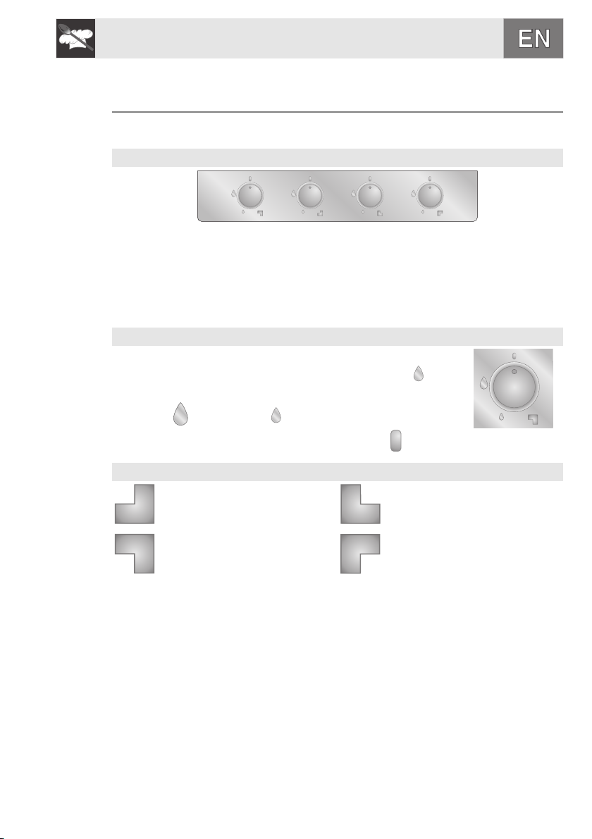
MODEL 60 CONTROL PANEL
DESCRIPTION OF THE KNOB
The flame is lit by pressing the knob and simultaneously
turning it anticlockwise to the minimum flame symbol .
To adjust the flame, turn the knob to the zone between
maximum and minimum .
Turn off the flame by turning the knob to position .
ARRANGEMENT OF THE BURNERS – Description of symbols
REAR LEFT REAR RIGHT
FRONT LEFT FRONT RIGHT
9
Instructions for the user
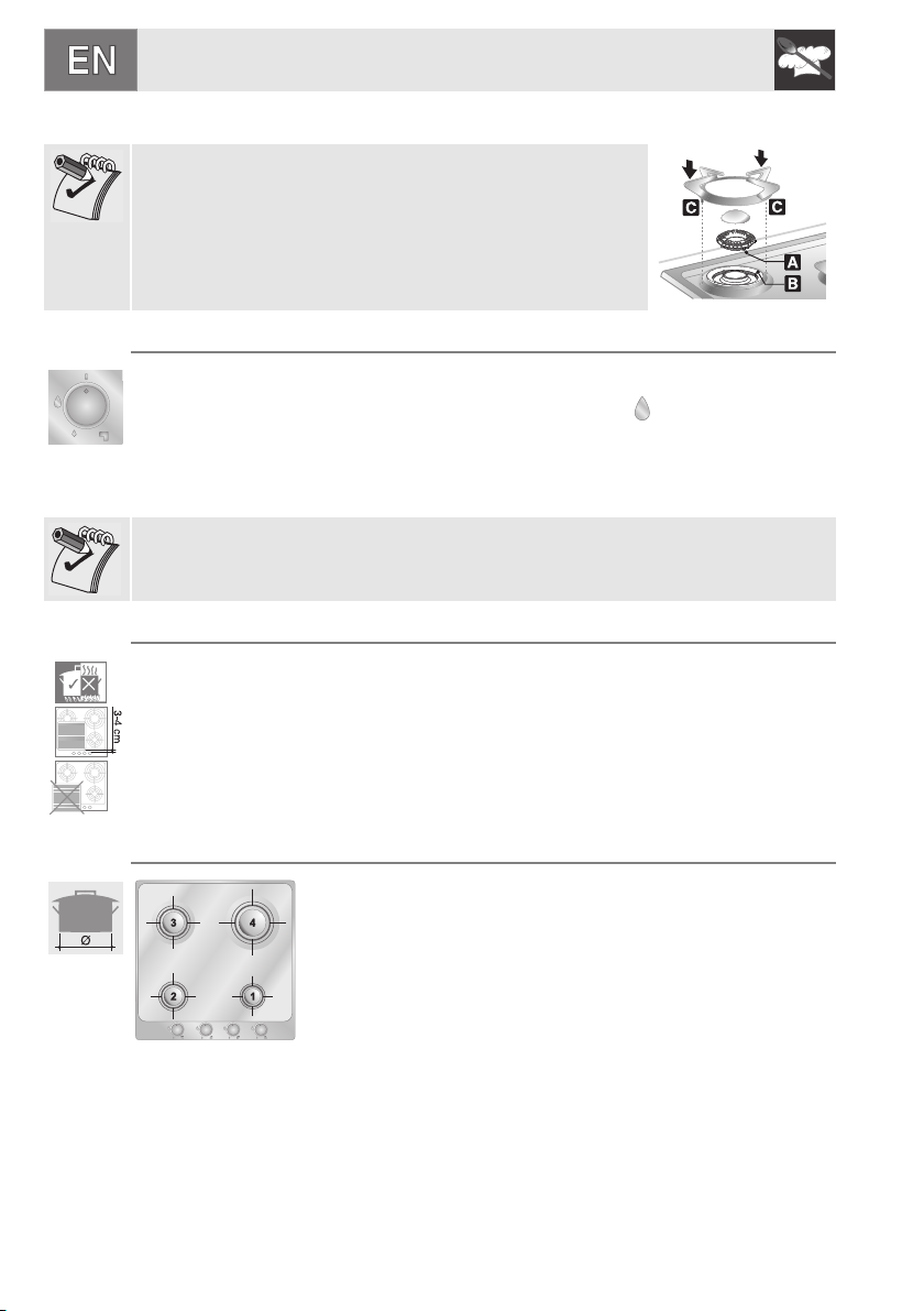
5. USING THE HOB
Check that the flame crowns, the burner caps and grids
are correctly assembled. Pins A of the flame crowns must
be inserted in housings
B of the burner rings, and pins C on the grids must be
blocked in their respective housings on the hob.
5.1 Ignition of the burners
The device is fit with electronic ignition. Simply press and simultaneously turn
the knob counter-clockwise on the low flame symbol , until the burner is
ignited.
The burner might go off when the knob is released. In this case repeat the
aforesaid operation keeping the knob pressed for more than 2 seconds.
Should the burners go off accidentally in the models with valves, a safety device
will trip after approximately 20 seconds to block the gas outlet even if the cock is
open.
5.2 Practical tips for using the burners
For better burner performance and minimum gas consumption, flat bottomed,
even pans must be used, with covers and proportional in size to the burners
(see paragraph “5.3 Pan diameters”).
To avoid overcooking or damage to the surface top while cooking, all pans or
griddles must be positioned within the cooking hob perimeter and must be at a
minimum distance of 3-4 cm from the knobs.
10
5.3 Pan diameters
HOB BURNER
1 Auxiliary
2 Semi rapid
3 Medium rapid
4 Large rapid
Ø min. and max. (in cm)
7-18
10-24
18-24
20-24

Instructions for the user
6. CLEANING AND MAINTENANCE
Before performing any operations requiring access to powered parts,
switch off the power supply to the appliance.
NEVER USE A STEAM JET FOR CLEANING THE APPLIANCE.
6.1 Cleaning stainless steel
To keep stainless steel in good condition it should be cleaned regularly
after use. Let it cool first.
6.1.1 Ordinary daily cleaning
To clean and preserve the stainless steel surfaces, use only specific products
that do not contain abrasives or chlorine-based acids.
How to use: pour the product onto a damp cloth and wipe the surface, rinse
thoroughly and dry with a soft cloth or chamois leather.
6.1.2 Food stains or residues
Never use metallic sponges or sharp scrapers as they will damage the
surface.
Use ordinary non-abrasive products for steel, with the aid of wooden
or plastic utensils if necessary.
Rinse thoroughly and dry with a soft cloth or chamois leather.
6.2 Cleaning the cooking hob parts
6.2.1 Knob
The knobs are made of stainless steel and therefore should be
cleaned in the same way as the hob.
6.2.2 Flame crowns
The flame crowns are removable. Wash them with hot water and
non-abrasive detergent. Be careful to remove all deposits.
When you replace them, make sure that they are completely dry
and inserted correctly in their housings (see Section “8. Using
the hob”).
11

Instructions for the user
6.2.3 Grids and burners cap (EVERSHINE treatment)
The special EVERSHINE treatment makes the polished
stainless-steel burners and grids highly heat resistant and
prevents yellowing due to the exposure to high temperatures.
Follow the cleaning instructions below for the best results and to
avoid damaging the treatment:
1 Remove the burner cap.
2 Pull one of the two horizontal spokes of the pan stand
upwards to extract it.
3 Wash these components with hot water and a non-abrasive cleaner, taking
care to remove any deposits. Do not use metal pan scourers, abrasive
sponges or sharp scrapers.
4 Dry the components.
5 Replace the burner caps on their corresponding crowns; position the grids,
ensuring that the pins C line up with their holes on the hob, then push them
down with the palm of your hand until they click into place.
6.2.4 Ignition plugs and safety devices
For good functioning of the ignition plugs and the safety devices,
keep them very clean.
Check frequently and clean with a damp cloth when necessary.
12
6.3 Preventive maintenance
This appliance does not need any special maintenance. However, a few simple
operations have to be carried out periodically to prevent malfunctioning:
Burners: the burners must be cleaned periodically to ensure correct conbustion
make sure that all the openings and flame ports are clean and free of obstacles,
and the burners rest firmly on their supports.
Gas connection: the gas connection must be checked periodically.
Flexible pipes: if a flexible pipe is used, it must be inspected periodically (once
a year) for leakages if the surface of the pipe appears rigid and cracked,
disconnect immediately the cooker from the gas supply and replace the pipe
with a new one.
Valves: if the gas valves get stuck or hard to turn, they need to be cleaned and
re-greased; this operation must be carried out by an authorised person.
Annual service by an authorised person is recommended, or if any of the
following conditions are noticed; incomplete ignition, appreciable yellow tipping,
carbon deposition, lifting, floating, lighting back or objectionable odour.

Instructions for the user
6.4 Problems and causes
Each of the following cases is caused by an abhnormal operation of the
appliance and should be dealt with by an authorised person: please contact
your local dealer or Service Center in case you detect any of these
malfunctioning.
PROBLEM CAUSE WHAT TO DO
The flame is very long
with bright yellow .
Black deposits on the
bottom of the pans.
The flame is very short
and noisy. The flame
moves away from the
burner ports.
The flame extingulshes
when the burner knob is
set to the low flame
position.
The valve knob is hard to
rotate.
Defect of comburent air
or incorrect injectors.
Burner dirty or flame
ports obstructed.
Excess of comburent air. Call Service Center
Incorrect adjustment of
the minimum heat input
or excess of comburent
air.
Gas valve worn out or
needs lubrification.
Clean the burner.
Call Service Center if the
problem remains.
Call Service Center
Call Service Center
13

Instructions for the installer
7. POSITIONING OF THE HOB
The following operation requires building and/or carpentry work so must be carried out by
a competent tradesman.
Installation can be carried out on various materials such as masonry, metal, solid wood or
plastic laminated wood as long as they are heat resistant (T 90°C).
7.1 Fixing to a support structure
Create an opening with the dimensions shown in the figure in the top surface of the
counter, keeping a minimum distance of 50 mm from the rear border.
This appliance is classified as “type Y” in relation to fire hazards and can therefore be
mounted against walls higher than the work surface on condition that a certain distance
“X” be kept between the appliance and the wall as shown in the figure so as to avoid
damage from overheating. Make sure there is a minimum of 600 mm between the hot
plate flames and any shelf that may be installed directly above them. In case of installation
on a hollow compartment with doors, a separating panel has to be placed under the hob.
Keep a minimum distance of 10 mm between the bottom of the unit and the panel surface.
The panel has to be easily removable to allow access in the event of technical service.
14

Instructions for the installer
Carefully position the insulation gasket (supplied) on the external perimeter of
the hole made in the top surface (see figures below) and try to make it stick to
the entire surface by applying light pressure with your hands. Refer to the
distances shown in the figure for the model to be installed, keeping in mind that
for both models the long front side has to skim the hole. Secure the hob to the
counter with brackets A (supplied). Carefully trim any excess from border B of
the gasket. The distances in the following drawing refer to the hole on the inner
side of the gasket.
The diagram below shows the exact positions of the holes to be used for
clamping the hob to the top correctly
Obstructions: location of gas and electric connectors (measured in mm).
60 cm
hob
A 45
B 290
C 45
D 45
15

Instructions for the installer
7.2 Clearances above and around domestic appliances
This appliance must be installed by an authorised person in accordance with
this instruction manual, AS/NZS 5601.1 – Gas installations (installation and pipe
sizing), local gas fitting regulations, local electrical regulations, Building Code of
Australia and any other government authority.
16
REQUIREMENTS
1 Overhead clearances – (Measurement A)
Range hoods and exhaust fans shall be installed in accordance with the
manufacturer’s instructions. However, in no case shall the clearance between the
highest part of the hob of the cooking appliance and a range hood be less than 600
mm or, for an overhead exhaust fan, 750 mm.
Any other downward facing combustible surface less than 600 mm above the highest
part of the hob shall be protected for the full width and depth of the cooking surface
area in accordance with Clause 5.12.1.2. However, in no case shall this clearance to
any surface be less than 450 mm.
2 Side clearances – (MeasurementsB&C)
Where B, measured from the periphery of the nearest burner to any vertical
combustible surface, is less than 200 mm, the surface shall be protected in
accordance with Clause 5.12.1.2 to a height C of not less than 150 mm above the
hob for the full dimension (width or depth) of the cooking surface area. Where the
cooking appliance is fitted with a ‘splashback’, protection of the rear wall is not
required.

Instructions for the installer
3 Additional requirements for Freestanding and Elevated Cooking
Appliaces – (MeasurementsD&E)
Where D, the distance from the periphery of the nearest burner to a horizontal
combustible surface is less than 200 mm, then E shall be 10 mm or more, or the
horizontal surface shall be above the trivet. See insets above.
NOTES
1 Requirement 3 does not apply to a freestanding or elevated cooking appliance which
is designed to prevent flames or the cooking vessels from extending beyond the
periphery of the appliance.
2 The ‘cooking surface area’ is defined as that part of the appliance
3 where cooking normally takes place and does not include those parts of the appliance
containing control knobs.
4 For definition of hob, see Clause 1.4.64.
5 For definition of trivet, see Clause 1.4.109.
6 Consideration is to be given to window treatments when located near cooking
appliances. See Clause 5.3.4.
7.3 Room ventilation
Caution – This hob may only be installed and operated in rooms permanently
ventilated in accordance with current regulations. For proper operation of a gas
appliance it is essential for the air necessary for combustion of the gas to be
able to flow naturally into the room. Air must flow directly into the room through
openings in its outside walls. This (these) opening (s) must have a free passage
cross-section of at least 100 cm2, or 200 cm2 for appliances not equipped with
gas safety device. These openings must be constructed so that they cannot be
obstructed indoors or outdoors, and should preferably be close to the floor on
the side opposite to the combustion gas discharge point. If it is not possible to
make the openings in the room where the cooker is installed, the necessary air
may be taken from an adjoining room, proveded it is not a bedroom or a room
with fire risk.
AUSTRALIA - the hob must be installed in accordance with AS/NZS 5601
ventilation requirements.
7.4 Discharge of combustion products
Discharge of combustion products must be guaranteed by means of hoods
connected to a natural draught flue with certain efficiency, or by means of forced
aspiration.
An efficient aspiration system requires careful planning by a specialist capable
of installing it, respecting the positions and distances prescribed
by standards. After installation, the installer must issue a certificate of
conformity.
17

Instructions for the installer
7.5 Gas connection
This appliance must be installed by an authorised
person in accordance with this instruction
manual, AS/NZS 5601 - Gas installations
(installation and pipe sizing), local gas fitting
regulations, local electrical regulations, local
water regulations, Building Code of Australia and
any other government authority. This appliance is
suitable for connection with rigid pipe or flexible
hose. The isolating manual shut-off valve
connection point must be accessible when the
appliance is installed. Flexible hose assembly
must be certified to AS/NZS 1869 class B or D, be
of appropriate internal diameter for the total gas
consumption, be kept as short as possible (not
exceeding 1200mm), must not be in contact with
the floor or any hot sharp surfaces. The hose
assembly must not be subject to strain, abrasion,
kinking or deformation.
Natural Gas: the supplied regulator must be fitted to the appliance inlet connection. Gas
pressure must be adjusted to 1.0 kPa when approximately 50% of the burners are on high
flame, the appliance test point is located on th regulator.
L.P.G.: the supplied test point adaptor must be fitted to the appliance inlet connection.
Gas pressure must be adjusted to 2.75 kPa, the appliance test point is located on the test
point adaptor.
In case the appliance fails to operate correctly after all checks have been carried out, refer
to the authorised service provider in your area. Gas leakage and operation of the
appliance must be tested by the installer before leaving. Check burner flames are blue in
colour, stable and completely ignite at both high and low flame settings with no
appreciable yellow tipping, carbon deposition, lifting, floating, lighting back or
objectionable odour. Test burners individually and in combination. When satisfied with the
operation of the cooker, please instruct the user on the correct method of operation.
18
Installation with the flexible hose must be carried out so that the length of the
piping does not exceed 2 metres fully extended; make sure that the hoses do
not come into contact with moving parts and that they are not crushed in any
way.

Instructions for the installer
7.6 Connection to liquid gas
Use a pressure regulator and make the connection on the gas cylinder following
the guidelines established by the regulations in force. Make sure that the feed
pressure complies with the values indicated in the table at point “9.2 Burner and
nozzle characteristics table”.
7.7 Electrical connection
Make sure that the voltage and capacity of the power line conform to the data
shown on the plate located under the casing. Do not remove this plate for any
reason.
The plug at the end of the supply cable and the wall socket must be of the same
type and must conform to the applicable legislation on electrical installations.
Make sure that the supply line is suitably earthed.
Fit power line with an omnipolar circuit breaker with a contact opening gap equal
to or greater than 3 mm in an easily accessible position close to the hob.
Avoid the use of adapters and shunts.
If the power cable is replaced, the crosssection of wires in the new cable must be
no less than 0.75 mm2 (3 x 0.75 cable),
remembering that the end for connection to
the appliance must have a longer earth
wire (yellow/green)
, longer by at least 20 mm. Only use a H05V2V2-F or similar resistance cable to
the maximum temperature of 90°C. Its replacement must be carried out be a
specialised technician who must carry out the network connection following the
diagram below.
L = brown
N - blue
= yellow/green
The manufacturer cannot be held liable for damage to persons or things caused
by non-observance of the above directions or by interference with any part of the
appliance.
19

Instructions for the installer
8. ADAPTATION TO DIFFERENT TYPES OF GAS
Before carrying out the following operations, disconnect the appliance from the
power supply.
The appliance is preset for natural gas NG at a pressure of 1.0 kPa. In the case
of operation with other types of gas, the burner nozzles must be changed and
the minimum flame adjusted on the gas taps. To change the nozzles, proceed
as described in the following paragraphs.
8.1 Removing the hob
Remove all of the burner components by following the numerical sequence
shown in the figure:
• Remove all of the knobs (1) by pulling them upward;
• Remove the grids (2), lifting up one of the two horizontal spokes;
• Remove the burner caps (3) and flame crowns (4);
• With wrench A (supplied), open the bayonet clamps on the burner rings by
levering on guides B;
• Insert a wrench or a screw driver in one of the holes of the tool to simplify
removal;
• After having removed all of the above-described components, raise the
surface to access the burners and gas taps.
20

Instructions for the installer
8.2 Adjustment for ULPG
Caution: The maximum torque of the screw C should not exceed 1 Nm.
Check that the connection has been made as
described in the “Gas connection” section.
Undo the screw “C” and push the air regulator “D”
fully down. Use a spanner to remove the nozzles
“E” and fit those of suitable type following the
instructions given in the tables for bottled gas
ULPG 2.75 kPa. The nozzle must not be
tightened to a torque of over 3Nm.
Burner ULPG – 2.75 kPa
Nominal gas
Consumption (MJ/h)
Auxiliary (1) 4.0 0.54
Semi rapid (2) 5.9 0.65
Medium rapid (3) 8.5 0.78
Large rapid (4) 9.5 0.85
Injector
(mm)
8.3 Adjustment for natural gas
The hob has been adjusted for natural gas at a pressure of 1.0kPa.
To allow the unit to work back with this type of gas, after it has been adjusted for
ULPG, perform the same operations described in paragraph “8.2 Adjustment for
ULPG”, but refer to the following table for the proper injectors.
21

Instructions for the installer
Burner NG – 1.0 kPa
Nominal gas
Consumption (MJ/h)
Injector
(mm)
Auxiliary (1) 4.2 0.92
Semi rapid (2) 5.9 1.10
Medium rapid (3) 8.6 1.25
Large rapid (4) 11.4 1.50
8.4 Primary air adjustment
Refers to distance “X”inmm.
BURNER
Auxiliary open 2
Semi rapid 2 2.5
Medium rapid 2 2
Large rapid 2 2
ULPG
2.75 kPa
To identify the burners on your hob, please refer to the illustrations in paragraph
“9.4 Arrangement of the burners on the hob”.
If having adjusted the air the flame appears as illustrated in the figure:
the following modifications must be made:
A: the flame is "noisy", unstable or "detaches" from the burner: the primary air is
too high.
B: The flame is opaque, dull or has yellow tips and "wraps around" the burner:
the primary air is too low.
C: The flame is blue, clear and stable, does not "detach" or "wrap around" the
burner: the air is adjusted correctly.
Natural Gas
1.0 kPa
22

Instructions for the installer
9. FINAL OPERATIONS
Follow the instructions given in paragraph “5.1 Removing the hob”, but in the
reverse order.
When replacing the burner rings, remember that they have to be tightened
completely by means of the wrench supplied, otherwise the flame interruption
zones on the flame crowns will not be aligned with the grid spokes.
When positioning the grids, make sure that the pins are
aligned with their seats in the surface, then press them in
with the palm of your hand until they lock in place.
9.1 Adjusting the minimum for natural gas
Reposition the components on the burner and
slide the knobs onto the tap rods.
Light the burner and set it to the minimum
position .
Extract the knob again and turn the adjustment
screw inside or next to the tap rod (depending
on the model) until the correct minimum flame
is achieved.
Refit the knob and verify that the burner flame
is stable (when turning the knob rapidly from
the maximum to the minimum position the
flame must not go out).
9.2 Adjusting the minimum setting for LPG
To adjust the minimum setting with LPG, you must tighten the screw inside or
next to the tap rod (depending on the model) fully in a clockwise direction.
The diameters of the by-passes for the individual burners are given in the table
“10.3 Burner and nozzle characteristics tables”.
9.3 Lubrication of gas taps
Over time the gas taps may become difficult to turn and get blocked. Clean them
internally and replace the lubrication grease. This procedure must be carried
out by a specialised technician.
23

Instructions for the installer
9.4 Arrangement of the burners on the hob
BURNERS
1 Auxiliary
2 Semi rapid
3 Medium rapid
4 Large rapid
When replacing the burner rings, remember that they have to be tightened
completely by means of the wrench supplied, otherwise the flame interruption
zones on the flame crowns will not be aligned with the grid spokes.
24


 Loading...