

Smeg P23 LINEAR,P23LIN,P23 CLASSIC,P23CL,L23 LINEAR,L23LIN,L23 CLASSIC,L23CL,L30 FAB,L30FA Installation & User's Instructions
INSTALLATION & USER INSTRUCTIONS
All instructions must be handed to the user for
safekeeping.
MODELS COVERED BY THESE INSTRUCTIONS
P23 LINEAR - P23LIN
P23 CLASSIC - P23CL
L23 LINEAR - L23LIN
L23 CLASSIC - L23CL
L30 FAB - L30FAB
SMEG (UK) LTD
3 Milton Park
Abingdon, Oxon
OX14 4RN
WALL MOUNTED HIGH EFFICIENCY GAS FIRE
P23 Linear P23 Classic
L23 Classic
Please note : Except where otherwise stated, all rights,
including copyright in the text, images and layout of this
booklet is owned by Smeg (UK) Ltd. You are not permitted
to copy or adapt any of the content without the prior written permission of Smeg (UK) Ltd.
This product is tested and approved to EN14829 : 2007.
L23 Linear
L30 Fab
© 2012 Smeg (UK) Ltd.
1
Rev. B 03/12
GB IE
• This appliance is a high efficiency, flueless catalytic flame effect gas fire. It provides radiant and convected warmth both efficiently
and safely utilising the latest type catalytic converter and burner technology.
• The appliance does not require a flue system of any type as the catalytic converter cleans the flue products to provide a complete
combustion system, which is intrinsically safe. It is designed to operate on Natural Gas and is factory set for operation on the gas
type, and at the pressure stated on the appliance data plate.
• The appliance incorporates a combustion monitoring system (Oxygen Depletion System). It must not be adjusted or put out of
operation. If replaced then manufacturer’s original parts must be used.
• This appliance must be installed by a competent (GAS SAFE registered) person to ensure that the size of the room in which the
appliance is to be installed is sufficient and the ventilation provision for that room is sufficient for the appliance. Details of how to
determine the suitable room size is given in section 3.1 of these instructions and details of how to determine suitable ventilation are
given in section 4.1. LPG models must not be installed in cellars, basements or any room which is completely below ground level.
• In the event of gas leakage from the appliance, the gas supply must be turned off at the nearest isolating valve.
• The appliance must be installed in accordance with the following:
• Failure to comply with the above could lead to prosecution and deem the manufactur-
er’s warranty invalid.
• This appliance must be installed in accordance with the rules in force and used only in a
sufficiently ventilated space. The appliance is designed to fit various types of situations as
described in sections 3.0 and 4.0. The appliance must be installed in a correctly sized room
(see section 3.1), and the correct purpose provided ventilation must be provided (see section 4.1).
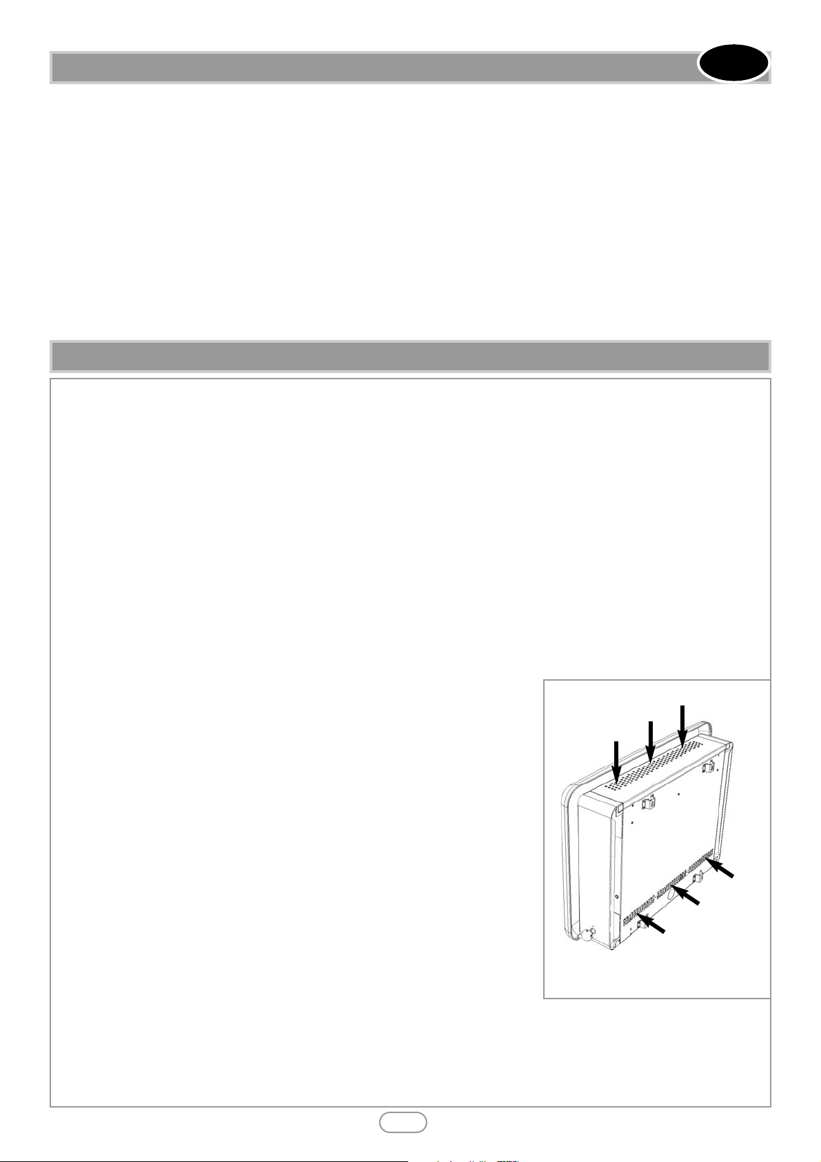
• On no account should the appliance inlet or outlet openings be blocked or obstructed
in any way (see figure 1). Do not place objects on top of the appliance. Do make sure the
appliance is installed on a flat wall.
• It should be noted that heaters create warm air currents. These currents move heat to
wall surfaces next to the heater. Installing the heater next to vinyl or cloth wall coverings
or operating the heater where impurities in the air (such as tobacco smoke, candle smoke
etc.) exist, may cause the walls to become discoloured.
• This appliance is intended as a secondary source of heat only and should not be used in
a room without some form of background heating present. If the appliance is used in a
room as the sole source of heat, then condensation may occur on colder surfaces within
the room.
• On first light up of a new appliance, burning off of high temperature paint and lubricants
may occur for the first few hours of operation. During this period some smoke may be
emitted from the outlet grille, this should be no cause for concern. Accordingly, the room
should be well ventilated with all windows and doors open during this period. During this
period the appliance may cause smoke alarms to sound. If this happens, reset the alarms,
but do not remove the batteries.
• WARNING: Due to the nature of this product the area around the top of the appliance (i.e. the grille) gets very hot. Care should
be taken when operating the appliance. The manufacturer of this appliance considers all surfaces as working surfaces with the
exception of the control knob. The guard (glass front) is to prevent risk of fire or injury from burns and no part of it should be
permanently removed. It Does Not Give Full Protection For Young Children Or The Infirm. Where young children, pets,
the elderly or infirm are concerned, a suitable fireguard should be used.
• Consult ALL instructions before installation and use of this appliance. This appliance is free from any asbestos material.
Section Contents Page No.
1.0 Important Notes 2
2.0 Appliance Data 3
3.0 Installation Requirements 3
3.1 Room Sizing 3
4.0 Site Requirements 3
4.1 Ventilation 3
5.0 Unpacking the Appliance 5
5.1 Component Checklist 5
6.0 Gas Supply Routes 5
7.0 Fixing the Appliance 5
7.1 Checking the Burner & Spark Gap 6
8.0 Testing and Commissioning 6
Section Contents Page No.
8.1 Operating the Appliance 7
8.2 Setting pressure 7
8.3 Fitting the Decorative Frame 8
9.0 Briefing the customer 8
10.0 Servicing 8
10.1 Servicing the Burner Unit 9
10.2 Pilot Assembly 9
10.3 Catalysts 10
10.4 Testing for Firebox Leakage 10
11.0 Troubleshooting Guide 11
12.0 Appliance Dimensions 12
1.0 IMPORTANT NOTES
INSTALLATION INSTRUCTIONS
© 2012 Smeg (UK) Ltd.
Note : L30FAB shown from rear as example,
however the air inlet and outlet openings are in
the same relative positions on all models.
Figure 1
Outlet openings :
DO NOT BLOCK
Inlet openings :
DO NOT BLOCK
2
GB IE
• Manufacturers' Instructions.
• The Building Regulations issued by the Department for Communities and Local Government, the Building Standards (Scotland)
(Consolidation) Regulations issued by the Scottish Development Department.
• Relevant British standards insofar as the relevant areas are not covered by these instructions.
• For Republic of Ireland, reference should be made to the current edition of IS813 (the relevant standards governing installation).
2.0 APPLIANCE DATA
© 2012 Smeg (UK) Ltd.
3
GB IE
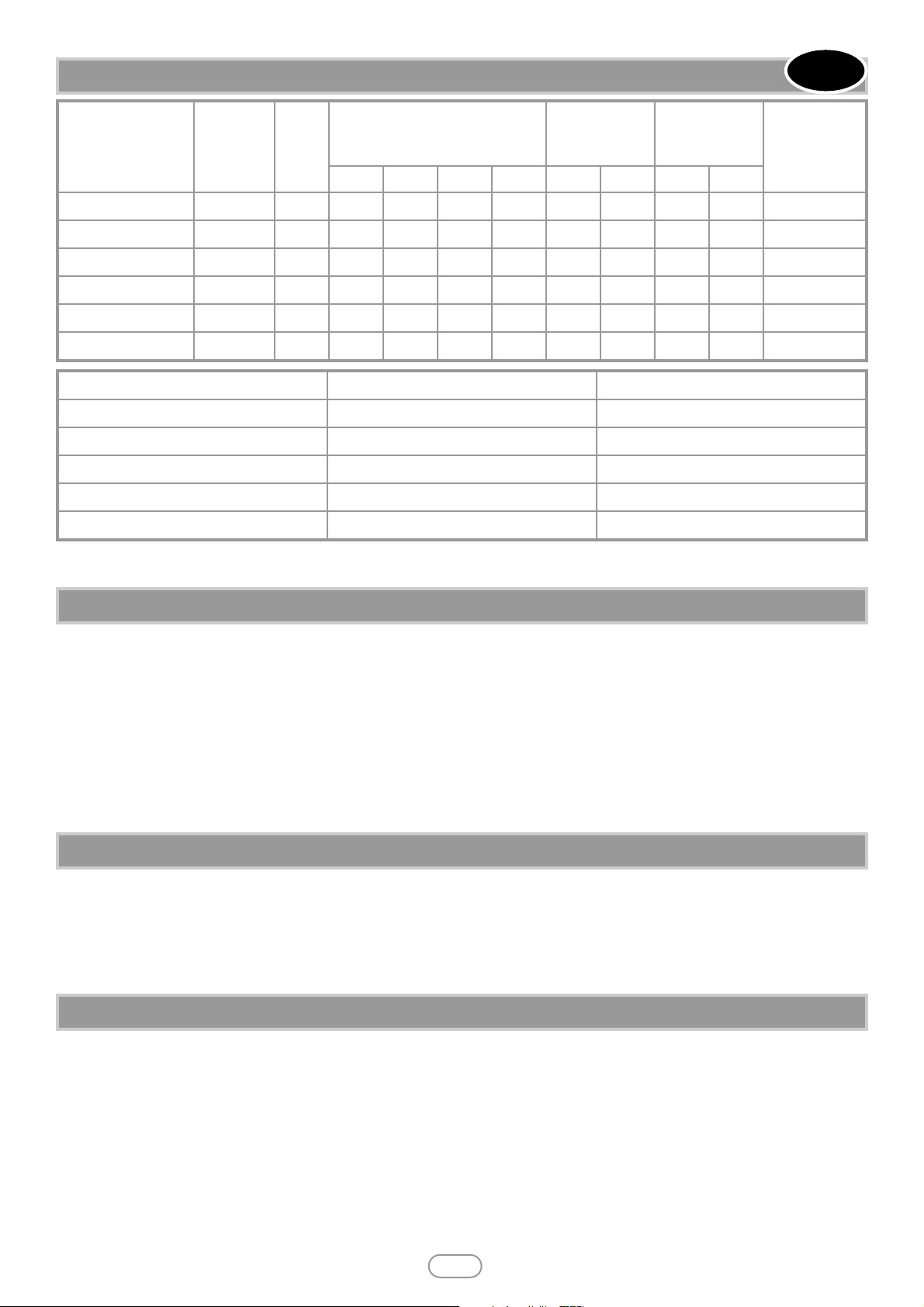
Model
Country of
destination
Cat
Inlet/Operating pressure
(±2.0 mbar)
Max Energy
Input (kW)
Min Energy
Input (kW)
Main burner
Flow Restrictor
G20 G25 G30 G31 Gross Net Gross Net
P23 Natural gas GB/IE
I
2H
20 -
- - 2.0 1.8 1.0 0.9 Stereo 1.30
P23 Propane GB/IE
I
3P
--
- 37 1.7 1.55 1.0 0.92 Stereo 0.65
L23 Natural gas GB/IE
I
2H
20 -
- - 2.0 1.8 1.3 1.15 Stereo 1.30
L23 Propane GB/IE
I
3P
--
- 37 1.7 1.55 1.3 1.2 Stereo 0.65
L30 Natural gas GB/IE
I
2H
20 -
- - 2.6 2.35 1.5 1.35 Stereo 1.50
L30 Propane GB/IE
I
3P
--
- 37 2.2 2.0 1.5 1.38 Stereo 0.86
Specifications NG Models LPG Models
Oxypilot SIT 9082/SIT 9114 SIT 9286/Seagas P5-19
Gas Control Copreci 21400 Copreci 21400
Gas Inlet 8mm restrictor elbow 8mm restrictor elbow
Ignition Double Piezo Spark Double Piezo Spark
Spark Gap 3.5 - 4.5mm 3.5 - 4.5mm
Please see Data Badge affixed to appliance for current data.
This appliance is for use only with the gas type, and at the pressure stated on the appliance Data Badge.
If the appliance is to be sited near a disused or unserviceable fireplace served by a natural draught flue then the old flue must be
sealed off. It will be necessary to ventilate the old flue to prevent condensation and dampness forming, however any air vent used
to ventilate the old flue must not be sited within 500mm of this appliance. If the flue can be ventilated to the outside of the building then this is usually the best solution. If in doubt then advice should be sought from a local building control officer. The appliance is designed to be wall mounted. If the appliance is to be mounted on a newly fabricated area of wall that also serves the purpose of sealing off the old flue then it is very important that there are no holes, gaps or otherwise in this wall that will allow
draughts from the old flue to enter the room, especially directly behind the appliance. Such draughts could affect the performance of the ODS system and result in nuisance cutting out, for example. If the gas supply pipe is to enter the appliance from the
rear, i.e. emerge from the wall behind the appliance, then any hole in the wall from which the pipe emerges must be tightly sealed.
P23 and L23 Models : The room size MUST be a minimum of 23m3(e.g. 3.06m x 3.06m x 2.45m or 10’1” x 10’1” x 8’).
L30 Models : The room size MUST be a minimum of 30m
3
(e.g. 3.5m x 3.5m x 2.45m or 11'6" x 11'6" x 8').
This is to allow adequate circulation of air and ensure the correct operation of the fire. This volume may include adjacent spaces
but these spaces must not be separated by a door. To calculate a room size in cubic metres (m
3
) divide the room volume in cubic
feet (ft
3
) by 35.3.
This appliance may be installed in any room in the home except bathrooms. In accordance with BS5871 part 4, installation in bedrooms is permitted. If the appliance is to be installed in a bedroom then an electronic carbon monoxide detector complying with
the current edition of BSEN 50291 must be installed in the same room as the appliance. For maximum safety it is recommended
that such device is continuously (mains) powered and arranged in such a way that the gas supply to the appliance is isolated in
the event of an alarm. The selection and installation of such device shall be in accordance with the current edition of BSEN 50292,
and the user must be briefed regarding the use and maintenance of such a device.
The appliance is designed to be versatile, and as such will operate correctly when exposed to normal gentle draughts experienced
within the home. It is not recommended, however that the appliance be installed in areas where it is likely to be directly exposed
to persistent strong draughts, that may be generated by outside doors, windows, air vents, air conditioning units, extractor fans,
ceiling fans etc. See section 4.1 for more information on ventilation.
3.0 INSTALLATION REQUIREMENTS
3.1 ROOM SIZING
4.0 SITE REQUIREMENTS
© 2012 Smeg (UK) Ltd.
4
Clearances to non-combustible materials
Non combustible surfaces are defined as brick, metal, marble, concrete etc. and also a
number of man-made materials impervious to flame. If in doubt refer to the material
manufacturer for further information before proceeding with installation.
Clearances to the sides of the appliance are 100mm (4”). Clearance to the front of the
appliance is 500mm (20”).
The back of the appliance may be installed directly onto a non-combustible wall, pro-
viding the area behind the appliance is flat and does not interfere with the various vent holes in the back panel of the appliance.
A non combustible shelf of any depth may be positioned above the appliance provided it is no closer than 400mm (16”) from the
top of the appliance glass panel and the wall above the appliance is non combustible. The appliance must not be positioned vertically within 60mm (2.4”) of a solid floor (i.e. wood or stone) or hearth. This dimension is measured vertically to the bottom of
the appliance firebox.
Clearances to combustible materials
Combustible materials are defined as wood, fabrics, or other materials likely to combust if exposed to flame. Generally, any material, which is likely to discolour, melt or misshape when exposed to moderate heat, should be considered as a combustible material or surface. Clearance to the sides of the appliance are 100mm (4”) but curtains, drapes and other fabrics are not permitted
within a distance of 500mm (20”) of the appliance sides. No such materials are permitted directly above the appliance regardless
of distance.
The minimum clearance to the ceiling above the appliance is 800mm (31.5”) measured from the top of the appliance glass panel.
Combustible materials should not be positioned directly in front of the appliance within a distance of one metre.
Under no circumstances should any electrical equipment e.g. plasma/LCD screen TV sets etc. be positioned on the wall above the
appliance.
The appliance is designed to be wall mounted alone and not in conjunction with any type of combustible fire surround. No combustible shelves should be positioned on the wall above the appliance. It should be established that any mirrors or picture frames
etc. to be positioned on the wall above the appliance are able to withstand prolonged exposure to moderate heat and moisture
before proceeding with their installation.
The back of the appliance may be installed directly onto a combustible wall, providing it is relatively flat and does not interfere
with the various vent holes in the back panel of the appliance. The wall must be structurally sound and constructed from a material capable of withstanding moderate heat. Brick, concrete, finished plaster, most types of conventional wall paper and dry-lined
plasterboard are examples of suitable materials. Materials such as flock, blown vinyl and embossed paper which are sensitive to
even small amounts of heat should be avoided as scorching and or discolouration may occur over time.
If the appliance is to be mounted on a dry lined wall or a timber framed construction wall then the integrity and ability of the
wall to carry the weight of the appliance must be confirmed. It is important in these circumstances that any vapour control barrier is not damaged, and that any structural members of the house frame are not damaged - refer to section 7.0.
The appliance must not be positioned vertically within 100 mm (4”) of a carpeted floor, rugs or fabric materials of any kind. This
dimension is measured vertically to the bottom of the appliance firebox.
If the room in which the appliance is installed is naturally ventilated, a minimum of 100 cm
2
purpose provided ventilation MUST
be provided for this appliance. This may be achieved either with one vent 100 cm
2
at a high or low position in the room, or split
ventilation i.e. 50 cm2be installed at high level and 50 cm2be installed at low level within the room. An openable window or
equivalent is also required. To reduce the possibility of draughts, road noise or insects entering the room via the air vent, we recommend the use an air vent of the type that feature internal baffles.
Ventilation fitted under, or within immediate vicinity of the appliance must not be used as it may adversely affect performance of
the ODS system. The appliance shall not be installed within one metre of any existing air vent, and any new air vent shall not be
installed within one metre of the appliance.
If the room in which the appliance is to be installed is served by heat recovery ventilation (HRV) or energy recovery ventilation
(ERV) then no purpose provided ventilation is required but a room air change rate of at least one air change per hour is required
for this appliance. The appliance MUST be interlocked with the ventilation system such that it is only possible to operate the appliance if the ventilation system is in operation.
In all cases, the requirements of any other gas, oil or solid fuel appliances operating in the same room or space must be taken
into consideration when assessing ventilation. Any ventilation fitted must comply (where applicable) with BS 5871 part 4 and BS
5440 part 2.
For Republic of Ireland refer to the current edition of IS813 and any relevant rules in force.
Note : With the appliance installed in the minimum size room and with the ventilation specified, the concentration of NO
2
in the
room is less than 300ppb.
This appliance is designed to be
wall-hung. Do not recess any part
of the appliance into the wall.
WARNING
4.0 SITE REQUIREMENTS (CONTINUED)
GB IE
4.1 VENTILATION
© 2012 Smeg (UK) Ltd.
5
Remove the outer packaging, remove any instructions or fixing kits. Read ALL these instructions before continuing to unpack or
install this appliance. Lift off the remaining packaging components and remove the contents of the box. Check that the components supplied correlate with the component checklist. Please dispose of all the packaging materials at your local recycling centre.
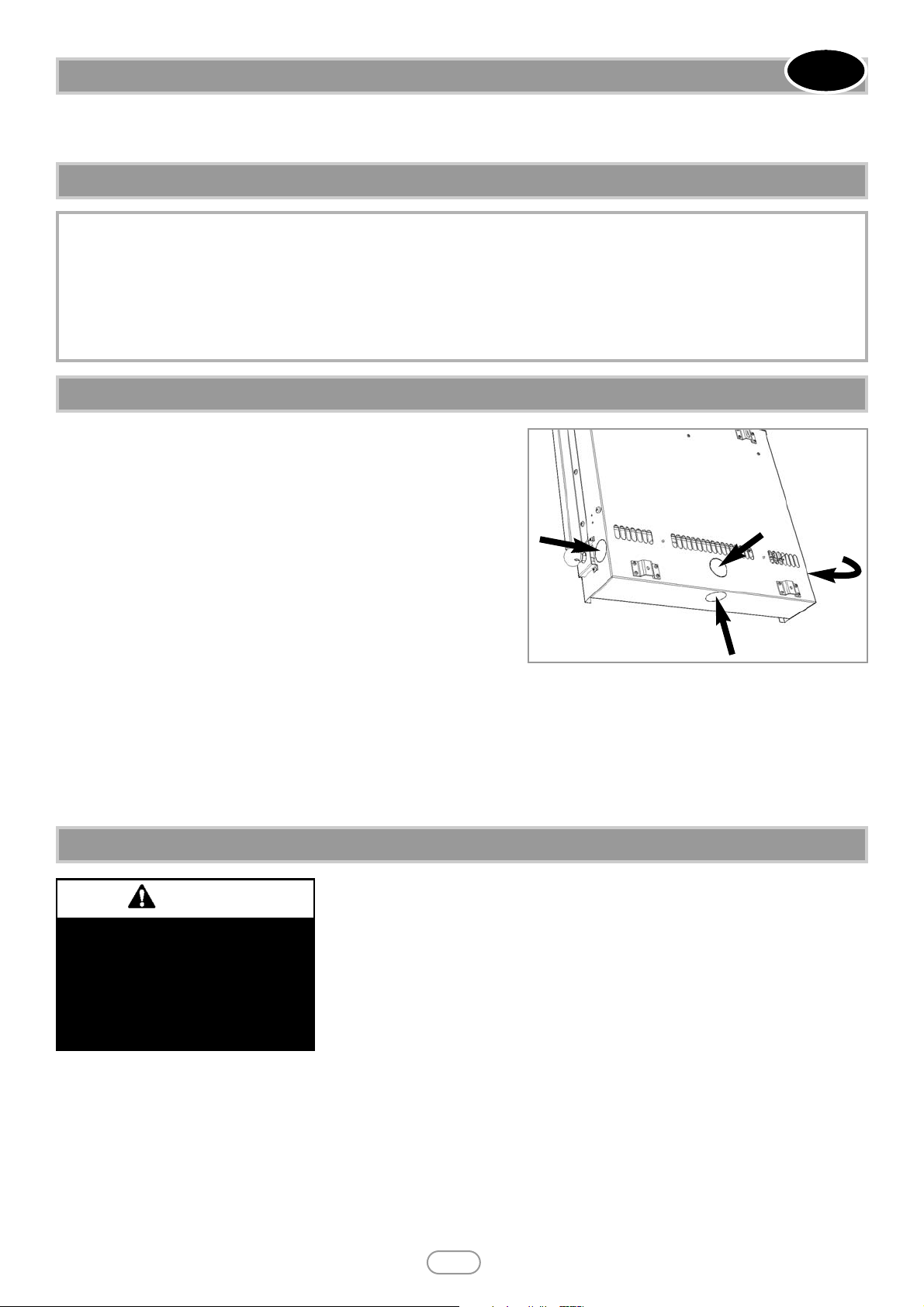
All models: There are four possible entry points for the gas supply
pipework to enter the appliance firebox. The L23 firebox is shown in figure 2 as an example, but the relative locations of these holes are the
same for all models.
These entry points are ‘knock out’ type holes. Non-concealed gas connections may be made using the entry points in the bottom or sides of
the firebox. A concealed gas connection may be made using the knock
out hole in the centre back of the firebox. Select the most appropriate
entry point and knock out the relevant hole with a sharp tap from a hammer and fit the rubber grommet supplied. A small incision can now be
made in the rubber to slip snugly around the outside of the supply pipe
and sleeving.
All installation pipework must be in accordance with the current edition of
National regulations/codes and the rules in force.
In order to avoid unnecessary pressure drops, use of small diameter pipe should be kept to a minimum, for example, we recommend no
more than 1.5 metres of 8mm pipe. If a concealed gas connection is to be made, the supply pipe should always be sleeved through walls
and floors using the shortest possible route. For concealed supply pipe routing, pipes must (where possible) be vertical and providing there
is sufficient wall thickness available, they should be placed in pipe chases. Horizontal pipe runs should be avoided. Prior to chasing a solid
wall, an inspection should be made to note the proximity of any cables/sockets outlets which may already be buried. Pipes must be secured
using suitable clips and protected against corrosion. Ideally factory finished protected pipework and fittings should be used. Joints should be
kept to a minimum and compression fittings must not be used. The pipework installation must be tested for tightness before any protection is applied and/or the pipework and fittings are buried.
Remove any protective film coatings from the finished/decorative surfaces of the appliance.
After having selected the final mounting position of the appliance, taking into account the
requirements as specified in sections 3 and 4 of these instructions, the integrity of the wall,
and the feasibility of the proposed supply pipe routing, the firebox of the appliance may be
secured to the wall.
To ensure customer safety, be sure to design the installation so that the strength of both
the wall and any wall fixings used are sufficient.
Smeg (UK) Ltd. assumes absolutely no responsibility for injuries and damages that may
occur due to improper installation or handling. The appliance should not be installed until
all wet plastering and/or dry wall sanding and wall painting has been completed. Do not block the ventilation holes of the appliance. The
wall onto which the appliance is installed must be flat. Install only on a vertical surface. Avoid sloped surfaces. Installation onto anything
other than a vertical wall may result in fire, damage or injury. If the appliance is to be mounted on the inner leaf of a conventional cavity brick wall, or a solid wall, then the wall plugs and fixing screws provided may be used.
Depending on the condition of the wall it may be necessary to use additional fixings. In this situation, any additional fixings and wallplugs
should be of the same size and type as the ones provided. At the appropriate stage of the installation, drill four holes using only a 8mm
masonry bit to a depth of 42mm. Insert the wallplugs provided ensuring they are flush to the wall.
If the appliance is to be mounted on a dry lined wall or a timber framed construction wall then efforts should be made to fix in at least
5.0 UNPACKING THE APPLIANCE
5.1 COMPONENT CHECKLIST
QUANTITY DESCRIPTION
1 Firebox and burner assembly
1 Set of manufacturers instructions
1 Decorative glass facia assembly (Linear and Classic models)
1 Painted decorative facia in one of several colours (Fab models)
1 Screw and wall plug pack
1 Rubber grommet
1 Fitting template
6.0 GAS SUPPLY ROUTES
Figure 2
GB IE
The wall where the appliance is
to be installed must be capable
of long-term support of the total
load of the appliance. Measures
should also be taken to ensure
sufficient strength to withstand
the force of earthquakes, vibration and other external forces.
WARNING
7.0 FIXING THE APPLIANCE
 Loading...