

Page 1
-EN- LT20/DS -
LT20/DS - INSTRUCTIONS FOR ASSEMBLY AND USE
Read the safety warnings and instructions for the thermodisinfectors in which the rack is used with
care, together with the safety instructions of the producer of the glassware and any other item placed on the
rack. Badly positioned items or glass which shatters during washing may cause dangerous injuries. If
necessary, washing results must be checked and subjected to non-visual inspections.
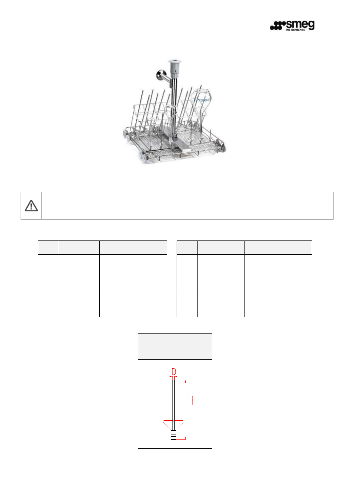
1 LIST OF COMPONENTS SUPPLIED
Qt.y
1
2
2
1
PART
NUMBER
TC40
U6220
U4160
TC40DS
DESCRIPTION
LM40 central pipe (for
version without DS
only)
stainless steel nozzle
D=6 H=220 (mm).
stainless steel nozzle
D=4 H=140 (mm).
LM40DS central pipe
(for DS version only)
Qt.y
2
12
1
Stainless steel nozzle with D=
NOZZLE
(E.g. U390 means
3mm and H= 90mm)
PART
NUMBER
U390
U6370
-
DESCRIPTION
stainless steel nozzle
D=3 H=90 (mm).
stainless steel nozzle
D=6 H=370 (mm).
Nozzle spanner
19390339900_LT20-DS_EN
1
Ed. 01 - 03/01/2012
Page 2
-EN- LT20/DS -
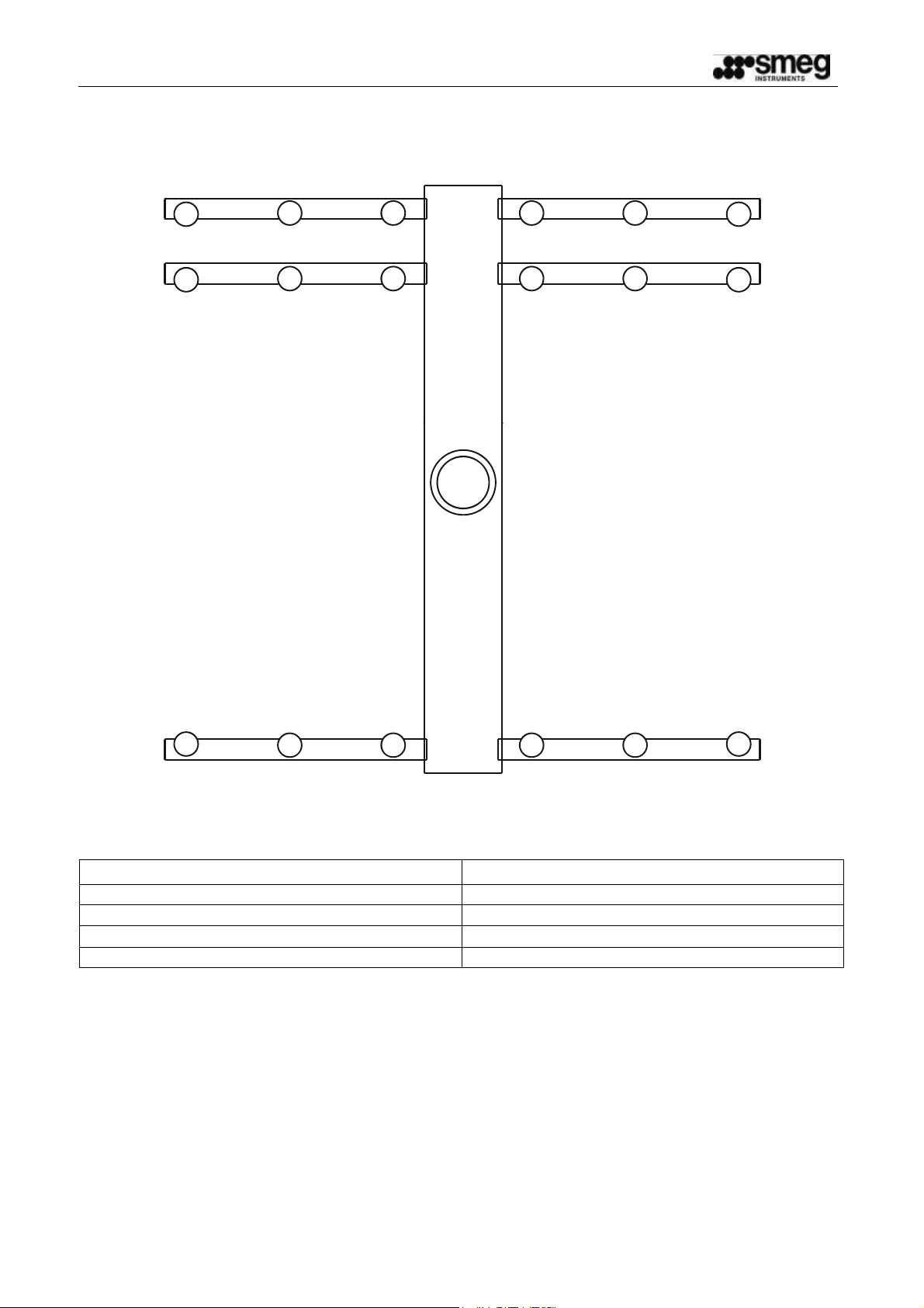
2 NOZZLE ASSEMBLY DIAGRAM
Rear
4
4
4 4
4 4
4
4
4
4
4
4
3
1
22
1
3
Front
POSITION DESCRIPTION
1
2
3
4
U390
U4160
U6220
U6370
19390339900_LT20-DS_EN
2
Ed. 01 - 03/01/2012
Page 3
-EN- LT20/DS -
A
B
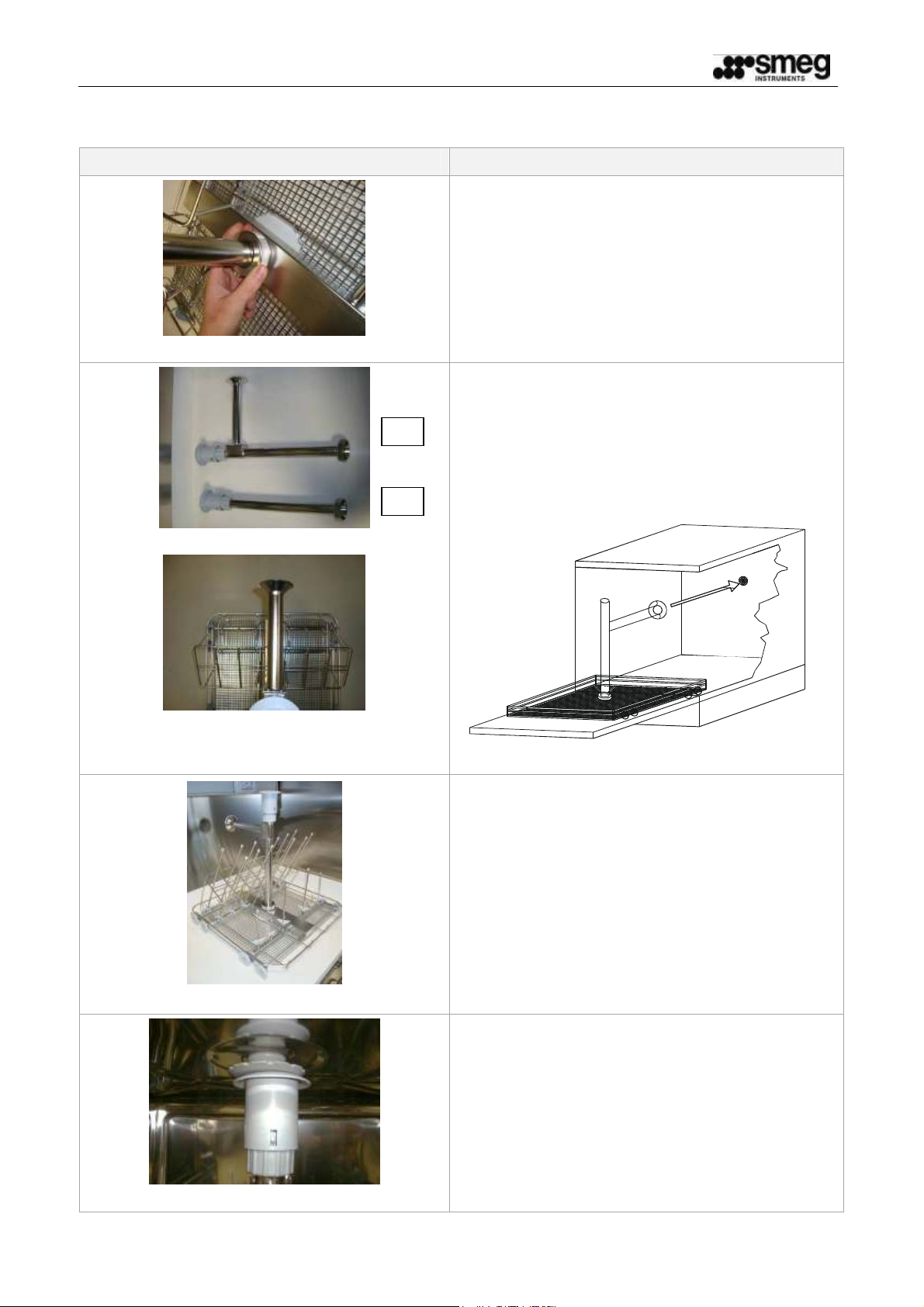
3 ASSEMBLY SEQUENCE
ILLUSTRATION PROCEDURE
Fig.1
Fig. 2
Insert the central pipe into place and tighten the
ring-nut to fix all parts.
If your product is equipped with the DS device,
the pack contains pipe B (TC40DS) instead of
the ordinary pipe A(TC40), in which case the
pipe B must be fitted as shown in figure 3, i.e.
with the pipe projecting towards the rear of the
rack, so that once it is inside the disinfector it will
be aligned with the connection (illustration
below).
Fig.3
Fig. 4
Fit the different types of nozzles in the positions
shown in the nozzle assembly diagram.
Tighten the nozzles with the spanner provided.
When inserting the rack in the disinfector, the
greatest care must be taken to ensure that the
tapered connection on the rack is aligned with
the one on the machine.
Fig.6
19390339900_LT20-DS_EN
3
Ed. 01 - 03/01/2012
Page 4
-EN- LT20/DS -
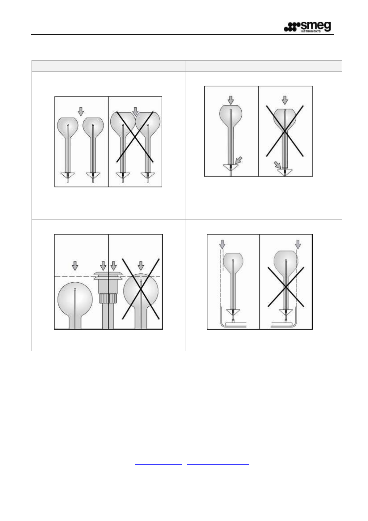
4 USE AND PRECAUTIONS
PROCEDURE PROCEDURE
Take care not to place pieces of glassware
touching each other.
Ensure that no glassware or any other item
for washing projects above the water intake.
Via Leonardo da Vinci, 4 – 42016 Guastalla (RE) Italy
Tel. +39 0522 8211 - Fax + 0522 821 592
E-Mail:
Glass must not rest on the nozzle; it must
stand on the base support, allowing the
water to come out of the nozzle freely.
Move the spring underneath the support to
prevent it from descending.
Ensure that no item for washing projects from
the rack after loading.
Smeg S.p.A.
Instruments Division
19390339900_LT20-DS_EN
4
Ed. 01 - 03/01/2012
 Loading...