

Page 1

Free Standing Gas Cooker
Installation and Operating Instructions
LF96105SS
LF66105SS
To avoid the risk of accidents or damage to the Gas Cooker,
it is essential to read these operating instructions
before it is installed or used for the first time.
And please keep this manual for later reference.
P/No.: MFL62060304
http://au.lge.com (Australia)
http://nz.lge.com (New Zealand)
Page 2

Contents
Introduction ................................................................................. 3
1. Instructions for safe and proper use.......................................3
Instructions for the installer ...................................................... 6
2. Installation of the appliance....................................................6
3. Adaptation to different types of gas ......................................11
4. Final operations....................................................................14
Instructions for the user .......................................................... 17
5. Description of controls..........................................................17
6. Use of the hob ......................................................................19
7. Use of the oven ....................................................................22
8. Electronic programmer (Only on equipped models).............26
9. Available accessories...........................................................29
10. Cleaning and maintenance.................................................30
11. Extraordinary maintenance.................................................33
These instructions are valid only for the end user countries
whose identification symbols appear on the cover of this
manual.
INSTRUCTIONS FOR THE INSTALLER: these are for the
authorised person who must carry out a suitable check of the gas
system, install the appliance, set it functioning and carry out an
inspection test.
INSTRUCTIONS FOR THE USER: these contain user advice,
description of the commands and the correct procedures for
cleaning and maintenance of the appliance.
2
Page 3

1. Instructions for safe and proper use
This manual is an integral part of the appliance and therefore must
be kept in its entirety and in an accessible place for the whole
working life of the cooker. We advise reading this manual and all
the instructions therein before using the cooker. Also keep the
series of nozzles supplied. Installation must be carried out by
qualified personnel in accordance with the regulations in force. This
appliance is intended for domestic uses and conforms to current
regulations in force. The appliance has been built to carry out the
following functions: Cooking and heating-up of food. All other
uses are considered improper.
The manufacturer declines all responsibility for improper use.
Do not leave the packing in the home environment. Separate the
various waste materials and take them to the nearest special
garbage collection centre.
It is compulsory that the appliance be grounded according to the
methods required by safety rules.
The plug to be connected to the power cable and the socket must
be the same type and must conform to current regulations.
The socket must be accessible after the appliance has been built in.
Never unplug by pulling out the cable.
Immediately after installation carry out a brief inspection test of
the appliance, following the instructions below. Should the
appliance not function, disconnect it from the supply and call the
nearest technical assistance centre.
Never attempt to repair the appliance.
DO NOT USE OR STORE FLAMMABLE MATERIALS IN THE
APPLIANCE STORAGE DRAWER OR NEAR THIS
APPLIANCE.
3
Introduction
Page 4
Introduction
DO NOT MODIFY THIS APPLIANCE
When not in use, make sure that the control knobs are in the
correct (OFF) position ●●.
Never put inflammable objects in the oven: They could be
accidentally catch fire and burn.
The I.D plate with technical date, serial number and brand name is
positioned visibly in the storage compartment.
The plate must not be removed.
Do not put pans without perfectly smooth and flat bottoms on the
hob grids.
During use the appliance becomes very hot. Take care not to
touch the heating elements inside the oven.
Do not use containers or broilers that extend beyond the outer
perimeter of the hob.
The appliance is designed for use by adults. Do not allow
children to go near or play with it.
When operating the grill all accessible parts could become very hot:
keep out of the way of children.
If the appliance is to be positioned on a platform it must be installed
in such a way as to prevent it from tilting off it.
This appliance is designed for cooking food and it shall not be used
as a space heater.
Do not spray aerosols in the vicinity of this appliance while it is in
operation.
4
Page 5
Where this appliance is installed in marine craft or in caravans, it
shall not be used as a space heater.
Do not apply decorative panels to the lower part of the cooker as
they may prevent correct air circulation and cause overheating.
Before the appliance is put into operation, all the labels and
protective films applied inside or outside must be removed.
The manufacturer declines all responsibility for damage to
persons or things caused by non-observance of the above
prescriptions or by interference with any part of the appliance or
by the use of non-original spares.
5
Page 6
Instructions for the installer
2. Installation of the appliance
It is the law that all gas appliances are installed by authorised
persons. Clearance around the cooker must comply with the
requirements of AS5601.
The manufacturer declines all responsibility for damage to
persons or things caused by non-observance of the above
prescriptions or by interference with any part of the appliance.
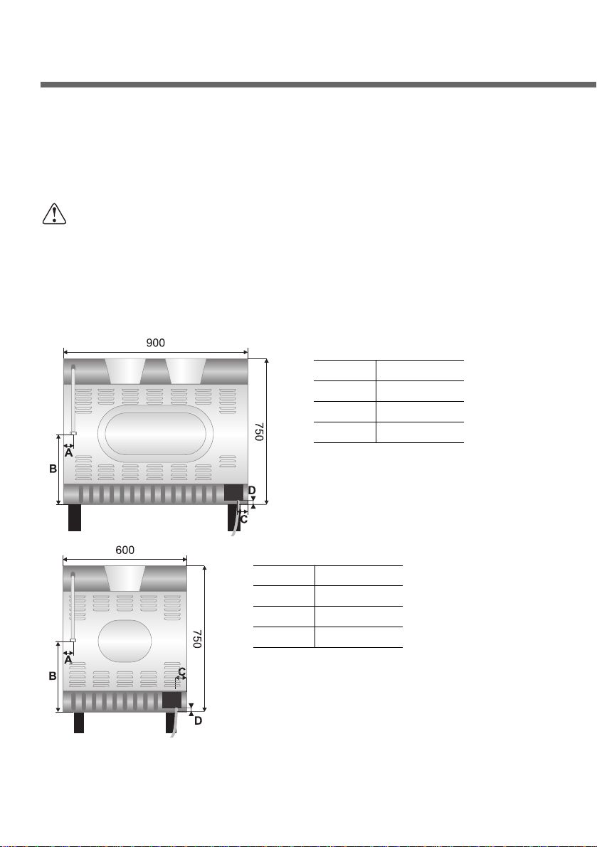
Overall dimensions: location of gas and electrical connection
points (all measures in mm).
6
A 60
B 410
C 60
D 70
A 60
B 410
C 100
D 150
Page 7
2.1 Electrical connection
Make sure that the power line voltage matches the specifications
indicated on the rating plate located inside the storage compartment.
This rating plate must never be removed.
If the appliance is connected to the supply by means of a fixed
connection, install a multipolar cut-out device on the line, with
contact opening distance equal to or greater than 3 mm, located
near the appliance and in an easily reachable position.
Connection to the supply may be fixed or with plug and socket. In
the latter case the plug and socket must be suitable for the cable
employed and conform with the regulations in force.
Regardless of the type of connection, earthing of the appliance is
absolutely obligatory. Before connection make sure that the supply
line is suitably earthed. Avoid the use of reducers, adapters or shunts.
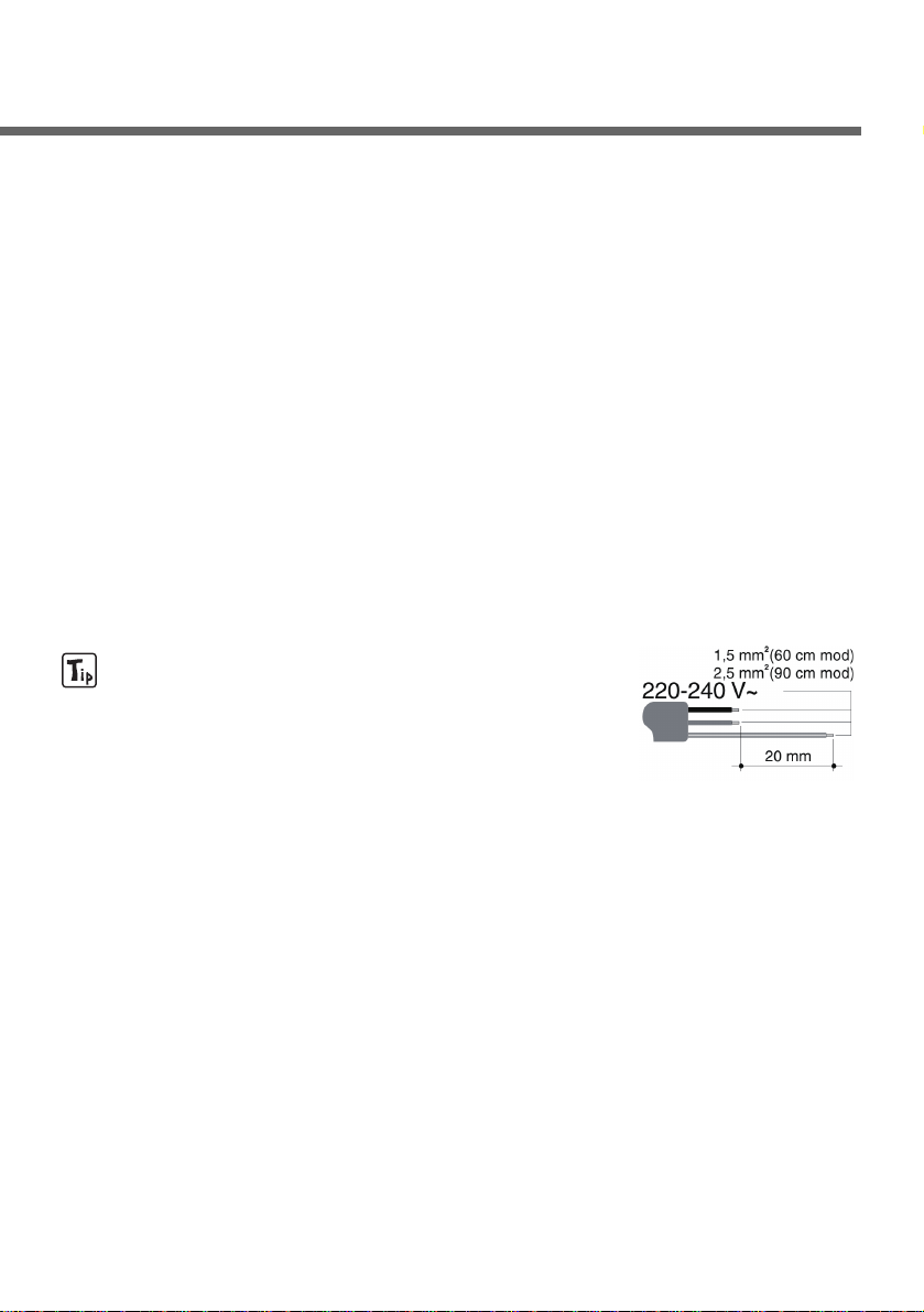
1. For operation on 220-240V~: use a
three-pole H05RR-F or H05V2V2-F cable
having a cross section of 3 x 2.5 mm
2
(90 cm wide models) or 3 x 1.5 mm
2
(60 cm wide models).
The cable end to be connected to the appliance must be provided
with ground wire (yellow-green) at least 20 mm longer.
7
Page 8
8
Instructions for the installer
2.2 Gas connection
Use pipe-joint compound made for use with Natural and U.L.P. gas.
This appliance is suitable for installation with Natural
Gas or ULPG (propane). Refer to page 12 for the
relevant burner pressure and appropriate injector
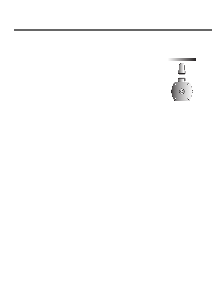
sizes. When the appliance is to be connected to
Natural Gas then the pressure regulator supplied must
be fitted to the gas inlet. A test point (for checking the
gas pressure) is supplied either with the regulator or
as a separate fitting in the case of ULPG (propane) appliances.
Connection of the appliance to the gas supply must be in
accordance with the requirements of AS5601. A
1
/2” BSP connector
at the inlet is recommended and the gas supply line to the
appliance must be of adequate length to allow sufficient withdrawal
of appliance for service or disconnection and be:
1. annealed copper pipe or;
2. flexible hose according to AS/NZ1869 & be at least Class
“B”, 10 mm diameter.
The cooker must be installed with provision to allow the gas to be
turned off and disconnected for servicing and removal of the
appliance as required from the gas supply. Before the cooker is
operated make certain all relevant parts are placed in the correct
position.
When the installation is completed the installation connections of
cooker will require to be leak tested, the burner operating pressure
and flame checked and adjusted.
Warranty service calls do not cover these adjustments!
To check the operating pressure of the appliance it is recommended
at least 2 large size burners are used. Ensure appliance is secured
to wall when installation is completed.
N.G. The regulator supplied must be fitted to the
1
/2” BSP thread at
the rear of the appliance. An approved manual shut-off valve must
be installed. The N.G. regulator must be checked and adjusted to
1.0kPa after installation.
Page 9
9
U.L.P.G: Can be connected to the inlet fitting directly.
The pressure must be checked to ensure it is operating
at 2.75kPa. A separate test point fitting must be installed
between the piping & the appliance for the pressure to
be checked to ensure it is operating at 2.75kPa.
Make the connection to the gas mains using a continuous
wall flexible steel pipe whose specifications comply with
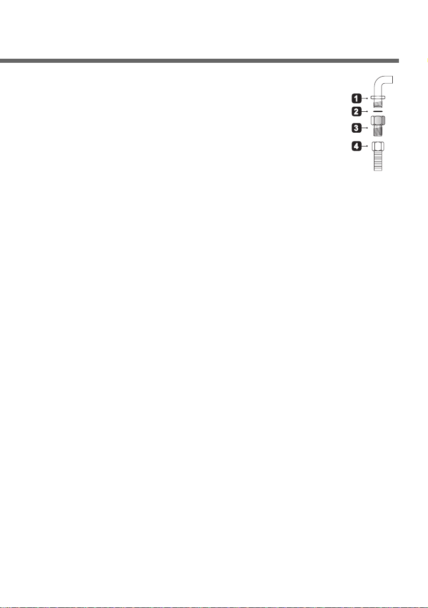
the current regulations. Carefully screw the connector 3 to the gas
connector 1 of the appliance, placing the seal 2 between them.
Apply a suitable sealing substance to the thread of the connector 3
and then tighten the flexible steel pipe 4 to the connector 3.
2.3 Combustion gas discharge
Combustion gases may be discharged by means of hoods
connected to a natural draught chimney or a fan extraction system.
An efficient extraction system requires precise planning by an
authorised specialist and must comply with the distances and
positions indicated by the regulations. After installation, the
specialist must issue a certificate of compliance.
2.4 Room ventilation
Caution – This cooker may only be installed and operated in rooms
permanently ventilated in accordance with current regulations. For
proper operation of a gas appliance it is essential for the air
necessary for combustion of the gas to be able to flow naturally into
the room. Air must flow directly into the room through openings in
its outside walls. This (these) opening (s) must have a free passage
cross-section of at least 100 cm
2
, or 200 cm2for appliances not
equipped with gas safety device. These openings must be
constructed so that they cannot be obstructed indoors or outdoors,
and should preferably be close to the floor on the side opposite to
the combustion gas discharge point. If it is not possible to make the
openings in the room where the cooker is installed, the necessary
air may be taken from an adjoining room, provided it is not a
bedroom or a room with fire risk.
Page 10
Instructions for the installer
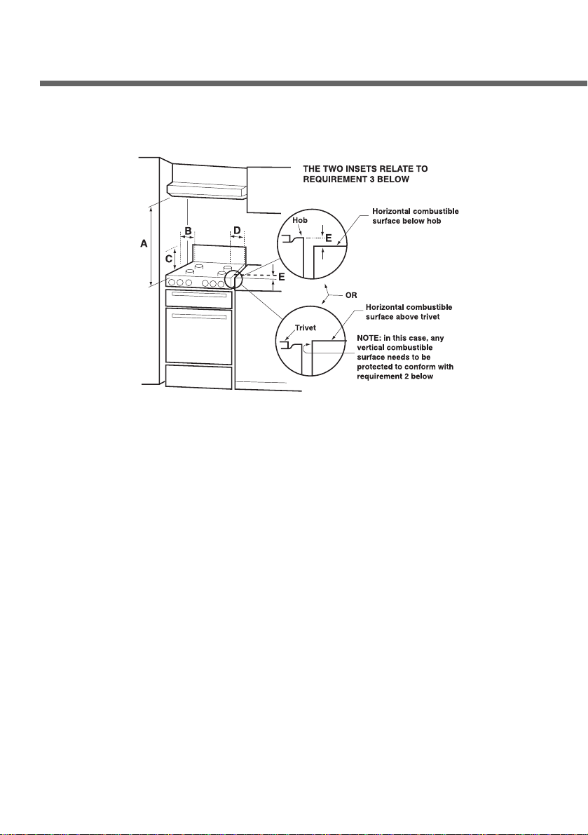
2.5 Clearance above and around domestic cookers
Extract from AS5601
REQUIREMENTS
1. Overhead clearances – (Measurement A)
Range hoods and exhaust fans shall be installed in accordance
with the manufacturer’s instructions. However, in no case shall
the clearance between the highest part of the hob of the cooking
appliance and a range hood be less than 600 mm or, for an
overhead exhaust fan, 750 mm.
Any other downward facing combustible surface less than 600
mm above the highest part of the hob shall be protected for the
full width and depth of the cooking surface area in accordance
with Clause 5.12.1.2. However, in no case shall this clearance to
any surface be less than 450 mm.
2. Side clearances – (Measurements B & C)
Where B, measured from the periphery of the nearest burner to
any vertical combustible surface, is less than 200 mm, the
surface shall be protected in accordance with Clause 5.12.1.2 to
10
Page 11

a height C of not less than 150 mm above the hob for the full
dimension (width or depth) of the cooking surface area. Where
the cooking appliance is fitted with a ‘splashback’, protection of
the rear wall is not required.
3. Additional requirements for Freestanding and Elevated Cooking
Appliaces – (Measurements D & E)
Where D, the distance from the periphery of the nearest burner to
a horizontal combustible surface is less than 200 mm, then E
shall be 10 mm or more, or the horizontal surface shall be above
the trivet. See insets above.
NOTES
1. Requirement 3 does not apply to a freestanding or elevated
cooking appliance which is designed to prevent flames or the
cooking vessels from extending beyond the periphery of the
appliance.
2. The ‘cooking surface area’ is defined as that part of the appliance
where cooking normally takes place and does not include those
parts of the appliance containing control knobs.
3. For definition of hob, see Clause 1.4.64.
4. For definition of trivet, see Clause 1.4.109.
5. Consideration is to be given to window treatments when located
near cooking appliances. See Clause 5.3.4.
3. Adaptation to different types of gas
Before performing any cleaning or maintenance work, disconnect
the appliance from the mains.
The hob of the cooker is adjusted for use with either natural gas at
a pressure of 1.0kPa. In the case of operation with other types of
gas the burner nozzles must be changed and the minimum flame
adjusted on the gas taps. To change the nozzles, proceed as
described below.
11
Page 12

12
3.1 Replacement of nozzles on the hob
This operation requires no primary air regulation.
1. Extract the grids and remove all the caps
and flame-spreader crowns;
2. unscrew the burner nozzles with a
7 mm socket wrench;
3. replace the nozzles according to the type of
gas to be used and the description in
paragraph "3.2 Burner and nozzle
characteristics table".
4.
Replace the burners in the correct position.
3.2 Burner and nozzle characteristics table
Instructions for the installer
ULPG (PROPANE) – 2.75 KPa
Nominal gas
consumption
(MJ/h)
Burner
Auxiliary
Semi rapid
Rapid
WOK
3.9
6.3
10
12.8
1.5
1.5
2.7
5.4
0,54
0,68
0,88
1,00
Turn-down gas
consumption
(MJ/h)
Injector
(mm)
NG – 1.0 KPa
Nominal gas
consumption
(MJ/h)
Burner
Auxiliary
Semi rapid
Rapid
WOK
4
7
12
15
1.5
1.5
2.7
5.4
0,90
1,20
1,55
1,75
Turn-down gas
consumption
(MJ/h)
Injector
(mm)
Page 13

13
3.3 Arrangement of the burners on the hob (Mod. 90 cm.)
BURNERS
1. Auxiliary
2. Semi rapid
3. Rapid
4. Triple crown
3.4 Arrangement of the burners on the hob (Mod. 60 cm.)
BURNERS
1. Auxiliary
2. Semi rapid
3. Rapid
4. Triple crown
Page 14
Instructions for the installer
14
4. Final operations
After replacing the nozzles, reposition the flame-spreader
crowns, the burner caps and the grids.
Following adjustment to a gas other than the preset one, replace
the gas adjustment label fixed to the appliance with the one
corresponding to the new gas. This label is in the packet together
with the nozzles.
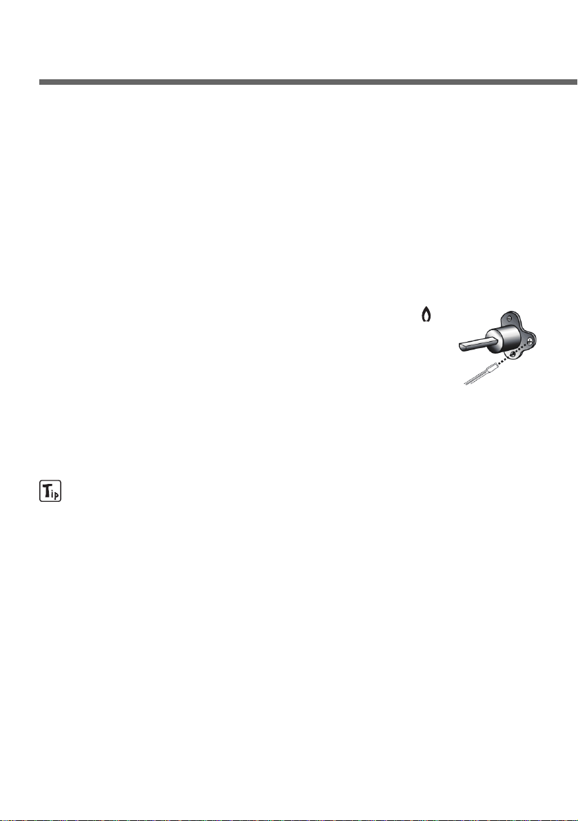
4.1 Regulation of the hob burner minimum level for natural gas
Light the burner and turn it to the minimum position .
Extract the gas tap knob and turn the adjustment
screw at the side of the tap rod until the correct
minimum flame is achieved.
Replace the knob and check burner flame stability:
(rapidly turning knob from maximum to minimum
position, the flame should not go out).
Repeat the operation on all the gas taps.
For models with valves, keep the knob at minimum level for about
1 minute to keep the flame lit and to activate the safety device.
4.2 Regulation of the hob burner minimum level for ULPG
In order to adjust the minimum with ULPG, the screw at the side of
the tap rod must be turned clockwise all the way.
Once the regulation has been completed, restore the seal on the
by-passes using paint or similar materials.
Page 15
15
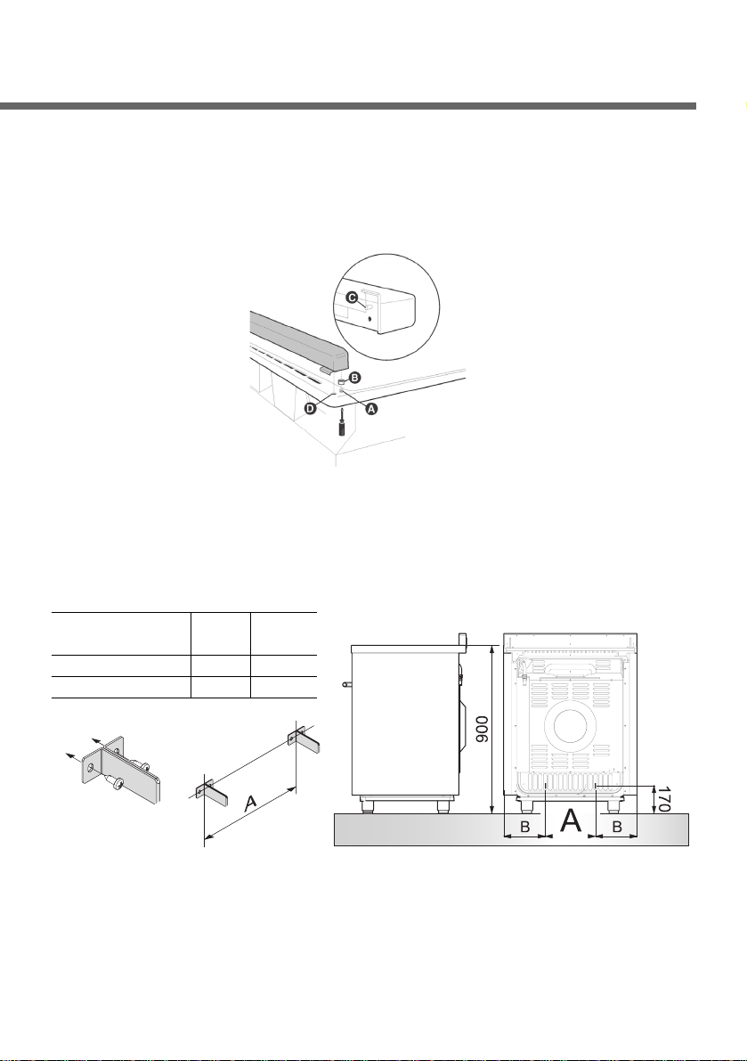
4.3 Mounting the rear top skirtboard (where applicable)
• Loosen nuts B.
•
Position the skirt above the top, taking care to align pins C with holes D.
• Secure the skirt to the top by tightening screws A.
4.4 Instruction for Wall fixing
1. Fasten the two wall brackets to the wall taking care to comply
withe the centre distances and measurements indicated in the
images below. The dimensions are given in mm.
Cooker AB
dimensions(cm)
60 262 168
90 457 220.5
Page 16
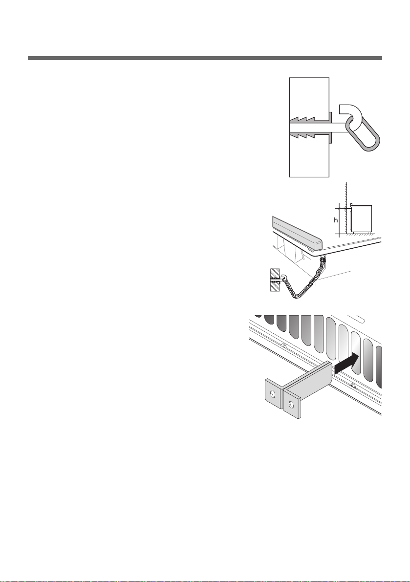
Instructions for the installer
2. Attach the chain to the cooker.
3. Stretch out the chain attached to the
cooker horizontally so that the other
end touches the wall.
4. Mark the wall in the position where the
hole is to be drilled.
5. Drill the hole, insert a wall plug and
attach the chain.
6. Once these operations are completed,
push the appliance against the wall
taking care to insert the wall brackets
correctly in the slots on the back of the
cooker.
16
Page 17
17
Instructions for the user
5. Description of controls
5.1 Front control panel
All the cooker controls and commands are on the front panel.
If the cooker is equipped with an electronic programmer, before
using the oven make sure that the symbol ; appears on the
display. See paragraph “8. ELECTRONIC PROGRAMMER”.
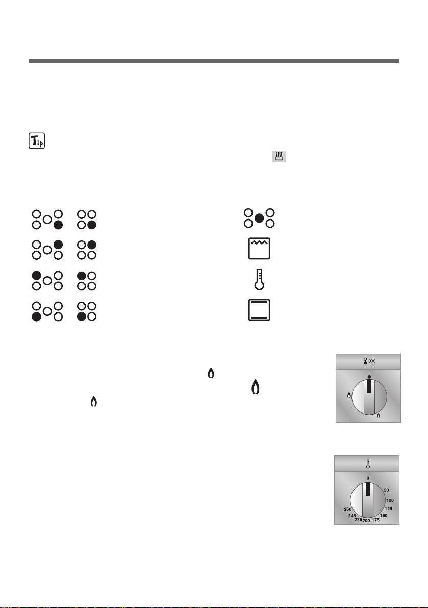
DESCRIPTION OF SYMBOLS
Front right burner
Back right burner
Back lefte burner
Front lefte burner
HOB BURNER COMMAND KNOB
The flame is lit by pressing the knob and turning it
anticlockwise to minimum flame . To adjust the
flame turn the knob between maximum ( ) and
minimum ( ). The burner goes out when the knob
is returned to the position ●●.
ELECTRIC OVEN THERMOSTAT KNOB
Selection of cooking temperature is carried out by
turning the knob clockwise to the required temperature,
between 50° and 260°C.
If the appliance has an electric oven, the warning light
will come on when the oven is heating up. When it goes
out it means that the required temperature has been
reached. Regular flashing means that oven temperature
is being constantly maintained at the programmed level.
central burner
variable gril
electric oven
thermostat
electric oven
function knob
Page 18
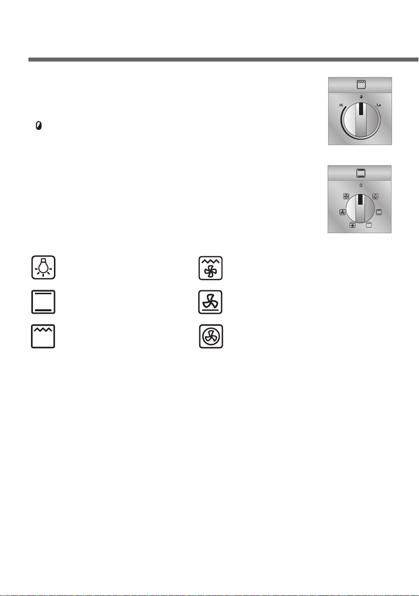
VARIABLE GRILL KNOB
This allows to vary heat intensity when cooking with
the grill. The knob can be set with continuity between
“ ” and the stop release position, which corresponds
to maximum heat.
ELECTRIC OVEN CONTROL KNOB
Each of the functions listed below can be used
(except the oven light and the small grill) only
together with the correct temperature thermostat
regulation as described on page 17 of this manual.
18
Instructions for the user
Oven light
Upper and lower
heating element
Grill element +
Rotisserie
Grill element + Ventilation +
Rotisserie
Lower heating element +
Ventilation
Ventilated heating element +
Ventilation
Page 19

19
6. Use of the hob
6.1 Lighting of the hob burners
Before lighting the hob burners check that the flame caps are in the
correct position and that their burner caps are in place, making sure
that the holes A in the flame caps correspond to the spark plugs
and thermocouples.
The optional grid B is for use with “woks” (Chinese pans).
To prevent deterioration of the hob we have equipped the cooker
with a raised pan stand C to be placed underneath pans more than
26 cm in diameter.
The supplied reduction rest C is used also for small pans.
The drawing next to each knob shows the
corresponding burner. The appliance has an
electronic lighting device. Simply press and turn the
knob anticlockwise to the minimum flame symbol ,
until the flame is lit. Hold the knob down for a few
seconds to allow the thermocouples to heat up. The
burner may go out when the knob is released: this is because the
thermocouple has not been sufficiently heated. Repeat the
operation holding down the knob a little longer. This operation is not
necessary for burners without thermocouples.
For models with thermocouples, should the burner accidentally
go out, a safety device will be activated which stops the gas
flow even if the tap is open.
Page 20

6.2 Practical advice for using the hob burners
For better use of the burners and lower gas consumption, use
covered vessel that are proportional in size to the burner to prevent
the flame from heating the sides (see paragraph “6.3 Diameter of
the vessels to be used on each burner”). When water reaches the
boiling point, lower the flame so that it doesn’t overflow. To avoid
burns or damage to the hob, all vessels or griddle plates must be
placed within the perimeter of the hob. All vessels must have a flat
and smooth bottom. When using fats or oils, be extremely careful
that they don’t overheat and catch fire.
If the flame accidentally goes out, turn off the control knob and wait
at least 1 minute before trying to re-light the burner.
Instructions for the user
20
Page 21
21
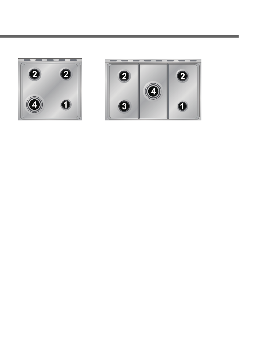
6.3 Diameter of the vessels to be used on each burner
BURNERS
1. Auxiliary
2. Semi rapid
3. Rapid
4. Triple crown
Ø min. and max.
(in cm)
12-14
16-24
18-26
18-26
Page 22

Instructions for the user
22
7. Use of the oven
For the models with electronic programmer, before using the
oven make sure that the display shows the symbol .
7.1 Warnings and general advice
Using the oven and the grill for the first time, heat them to the
maximum temperature (260°C) for as long as it takes to burn off
any production oil residues which could give a nasty flavour to the
food.
After a power cut, the oven display will flash intermittently and show
0:00 . To adjust refer to paragraph “8. ELECTRONIC
PROGRAMMER ”.
During cooking, do not cover the bottom of the oven with aluminium or
tin foil and do not place pans or oven trays on it as this may damage
the enamel coating. If you wish to use greaseproof paper, place it so
that it will not interfere with the hot air circulation inside the oven.
To prevent problems caused by steam in the oven,
open the door in two stages: half open (5 cm
approx.) for 4-5 seconds and then fully open. To
access food, always leave the door open as short a
time as possible to prevent the temperature in the
oven from falling and ruining the food.
Page 23
23
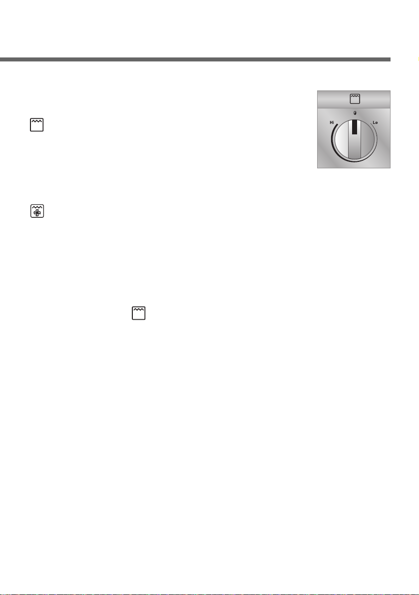
7.2 Use of the electric grill
For short cooking times, for example for browning
already-cooked meat, select the static grill function
; set the thermostat knob to maximum
temperature (260°C) and adjust grill intensity by
means of the variable grill knob. The ventilated grill
function allows actual cooking to be done, thanks to
the forced ventilation which lets heat penetrate inside
the food. For this type of cooking select the ventilated grill function
, set the thermostat knob to the desired cooking temperature
(never more than 225°C) and adjust grill intensity by means of the
variable grill knob. Cooking time must not exceed 60 minutes.
7.2.1 Operation of the grill + rotisserie
Both the static and the fan grill functions can be used for cooking in
combination with the rotisserie. Fit the spit rod into the rotisserie
bushing, select the or fan grill function and set the thermostat
knob to maximum temperature (260°C) and adjust grill intensity by
means of the variable grill knob, without exceeding the
3
/4
stroke as
shown in the figure.
Cooking procedures with grill and rotisserie must never last more
than 60 minutes.
All cooking procedures with grill + rotisserie must be carried out
with the door closed to prevent the knobs and front panel of the
appliance from overheating.
Page 24
Instructions for the user
24
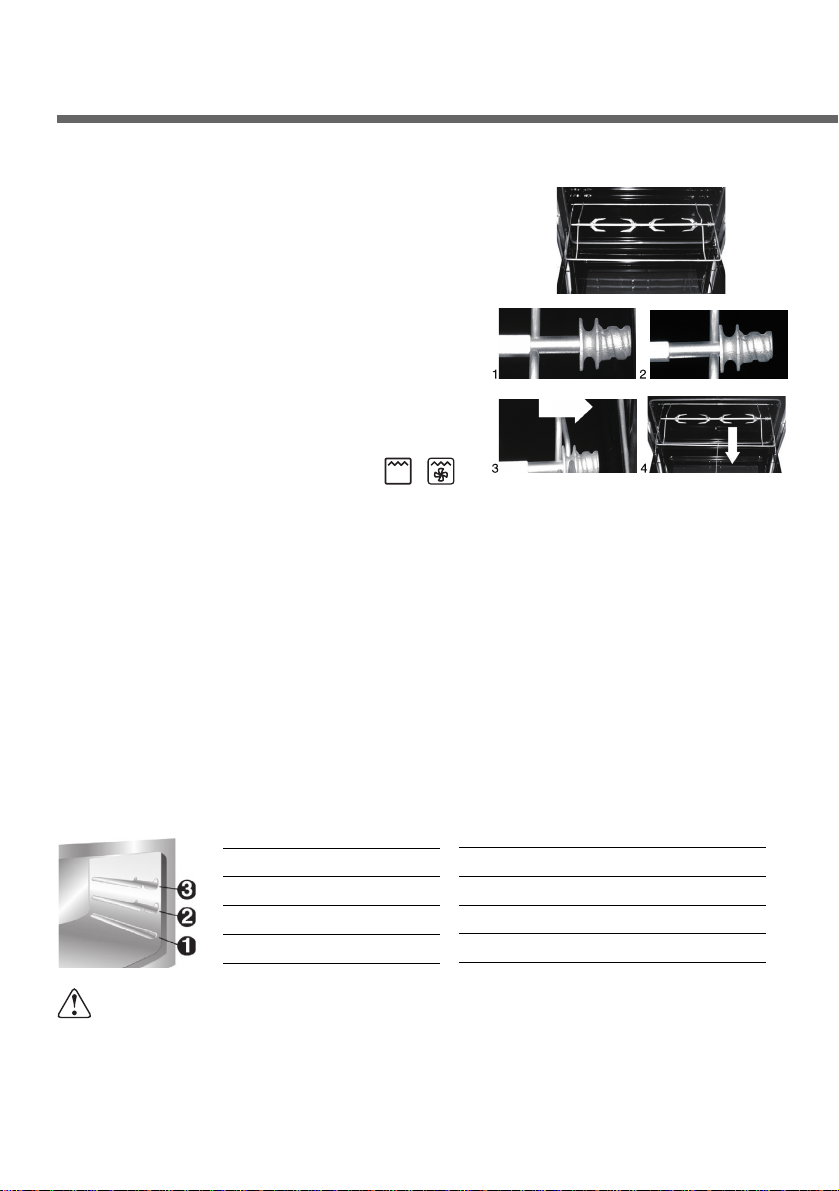
7.2.2 Using the rotisserie in cookers with maxi oven
Fit the supporting frame onto the
second runner up from the bottom so
that the seat to take the rod projects
outside the oven. Place the rod as
shown in the diagram (1) and push the
frame into the oven until the end of the
rod reaches the hole in the rotisserie
motor. Now push the rotisserie rod to
the left until it reaches the position
shown in the diagram (2). To activate
this function, turn the knob to ( / ).
These operations must be carried out with the oven switched
off and cold.
When cooking is over, use the tool provided to extract the rod from
the hole (3) and remove the frame (4) to bring the rotisserie rod out
of the oven cavity.
How to use the grill
Food should be flavoured and basted with oil or melted butter
before cooking. An oven dish should be used to contain the sauces.
The food should be placed on the oven shelf which is positioned on
one of the guides supplied with the different ovens, following the
instructions below:
FOOD
Flat or thin meat
Rolled roast joints
Poultry
WARNING
•
The oven accessories which may come into contact with food are
made from materials which conform to the standing directives.
• During and after use the accessible parts of the oven may be
very hot, and children must always be kept at a distance.
GRILLE ON THE SHELF
3
2 – 3
2 – 3
Page 25
25
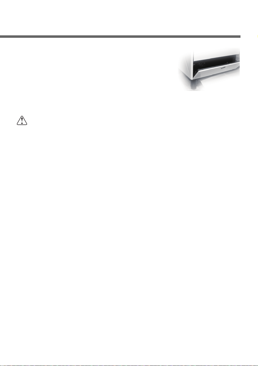
7.3 Storage compartment
A storage compartment, accessible by pulling
on the top edge of the door, is located beneath
the oven.
Never store inflammable materials such as
rags, paper or the like. The compartment is
intended only for holding the metal accessories of the range.
The inside of the compartment becomes very hot during
operationof the oven: turn off the oven and let it cool down
before opening the compartment door.
Page 26
Instructions for the user
26
8. Electronic programmer (Only on equipped models)
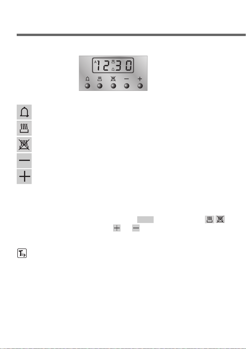
LIST OF FUNCTIONS
8.1 Clock adjustment
When using the oven for the first time, or after a power failure, the
display flashes regularly and indicates 0:00 . Press the keys
and at the same time the keys or : each single press changes
the time by 1 minute either up or down.
Before setting the programmer activate the desired function and
temperature.
Minute-Counter key
Cooking time key
End-of-Cooking key
Decrease time key
Increase time key
Page 27
27
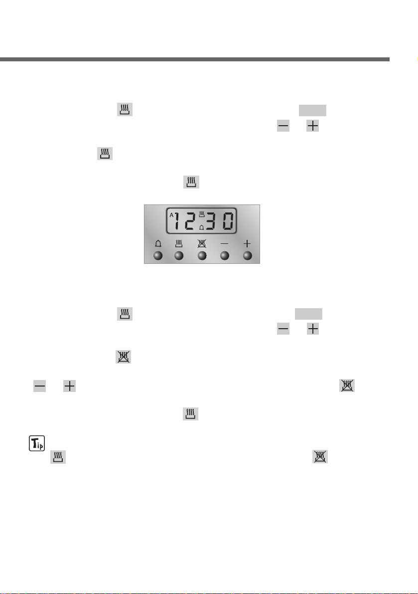
8.2 Semiautomatic cooking
Use this setting for automatic oven switch-off at the end of cooking time.
By pressing key , the display lights up, showing 0:00 ; keep the
key pressed and at the same time, press keys or to set the
cooking time.
Release key to start the programmed cooking time count. The
display will now show the right time
together with symbols A and .
8.3 Automatic cooking
Use this setting to automatically start and stop the oven.
By pressing key , the display lights up showing 0:00 ; keep the
key pressed and at the same time, press keys or to set the
cooking time.
By pressing key the sum of the right time + cooking time will
appear; keep the key pressed and at the same time, press keys
or to regulate the end of cooking time. Release key to
start the programmed count and the display will show the right time
together with symbols A and .
After set-up, to see the cooking time remaining, press the key
; to see the end of cooking time press the key . Set-up
with incoherent values is logically prevented (e.g. the contrast
between a cooking time and a longer period will not be
accepted by the programmer).
Page 28

8.4 End of cooking
When cooking is over, the oven will automatically switch off and, at
the same time, an intermittent alarm will sound. After switching off
the alarm, the display will once again show the right time together
with the symbol , indicating that the oven has returned to manual
operation mode.
8.5 Minute Counter
The programmer can also be used as a simple minute counter. By
pressing key , the display shows 0:00 ; keep the key pressed and
at the same time press keys or On releasing the key ,
programmed counting will begin and the display will show the
current time and the symbol .
After set-up, to see the remaining time, press the key .
Use as a minute counter does not interrupt functioning of the oven
at the end of the programmed time.
8.6 Adjusting alarm volume
The acoustic alarm has three different settings. These can be
adjusted, while the alarm is off, by pressing key .
8.7 Switching off the alarm
The alarm switches off automatically after seven minutes. They can
be manually de-activated by pressing the keys and together.
To switch off the appliance, rotate all the knobs to position 0.
8.8 Cancellation of set data
Once the programme has been set, keep the key of the function to
be cancelled pressed, while at the same time 0:00 is reached by
means of variation keys or . Time cancellation will be
considered as end-of-cooking time by the programmer.
8.9 Changing the set data
The cooking data entered can be changed at any time by keeping the
function key pressed and at the same time adjusting the keys or .
Instructions for the user
28
Page 29

29
9. Available accessories
The oven has 4 support for positioning plates
and racks at various heights.
Oven grill: for cooking food on plates, small
cakes, roasts or food requiring light grilling.
Plate grill: for placing above plate for cooking
foods that might drip.
Oven plate: useful for catching fat from foods on
the grill above.
Spit support (certain models only): to be
inserted in the 2ndguides of the oven before
using the spit.
Roasting spit (certain models only): useful for
cooking chicken, sausages and anything else
requiring uniform cooking over the whole surface.
Accessories on Request
You can order the lower base and self-cleaning oven panels
through Authorised Assistance Centres.
Page 30

10. Cleaning and maintenance
10.1 Cleaning stainless steel and enamelled versions
To maintain stainless steel in good condition clean it regularly after
each use, once it has cooled down.
10.1.1 Ordinary daily cleaning
To clean and preserve the stainless steel surfaces, always use only
specific products that do not contain abrasives or chlorine-based
acids.
How to use: pour the product on a damp cloth and wipe the
surface, rinse thoroughly and dry with a soft cloth or deerskin.
10.1.2 Food stains or residues
Do not use metallic sponges or sharp scrapers: they will
damage the surface.
Use normal non-abrasive products for steel, and a wooden
or plastic tool if necessary.
Rinse thoroughly and dry with a soft cloth or deerskin.
Do not allow residues of sugary foods (such as jam) to set
inside the oven. If left to set for too long, they might
damage the enamel lining of the oven.
10.2 Cleaning of the hob components
10.2.1 Grids
Remove the grids and clean them in warm water with a nonabrasive detergent, taking care to remove any encrustations.
Replace them on the hob.
Continuous contact of the grids with the flame can cause the
enamel near the hot areas to be altered. This is completely natural
and does not compromise the functionality of the component.
Instructions for the user
30
Page 31
31
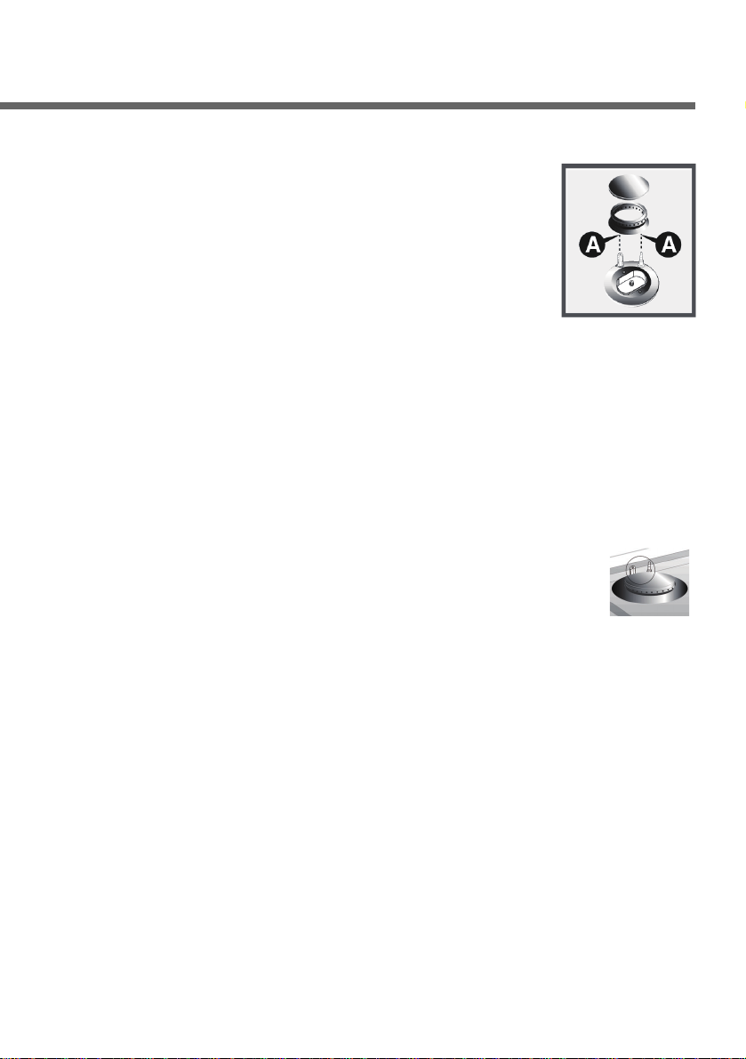
10.2.2 Burner caps and flame cap crowns
The caps and flame-spreader crowns are
extractable to facilitate cleaning. Wash them in hot
water with non-abrasive detergent, taking care to
remove any encrustations, and wait until they are
perfectly dry.
WARNING: do not wash these components in
the dishwasher.
Replace the flame-spreader crowns, checking that they are
positioned in their housing with their respective caps, taking care
that flame-spreader holes A correspond to the spark plugs and the
thermocouples.
10.2.3 The spark plugs and thermocouples
To function properly the spark plugs and thermocouples
must always be clean (on the models which are
equipped with them). Check them regularly and clean
with a damp cloth if necessary. Any dry residues can be
removed with a toothpick or a needle.
10.2.4 The burners
The burners can be left to soak in hot water and detergent.
Page 32
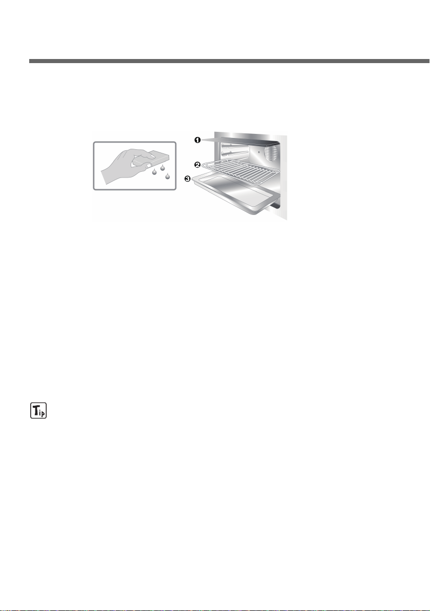
10.3 Cleaning of oven
For best oven upkeep clean regularly after having allowed to cool.
Take out all removable parts.
• Clean the oven grill with hot water and non-abrasive detergent.
Rinse and dry.
• Do not allow residues of sugary foods (such as jam) to set inside
the oven. If left to set for too long, they might damage the enamel
lining of the oven.
10.4 Door glass
The door glass should always be kept clean. Use absorbent kitchen
paper to clean. In case of tough spots, clean with a damp sponge
using regular detergent.
When cleaning, the appliance must be dried thoroughly
since detergent and water drips might damage its operation
and appearance.
Instructions for the user
32
Page 33
33
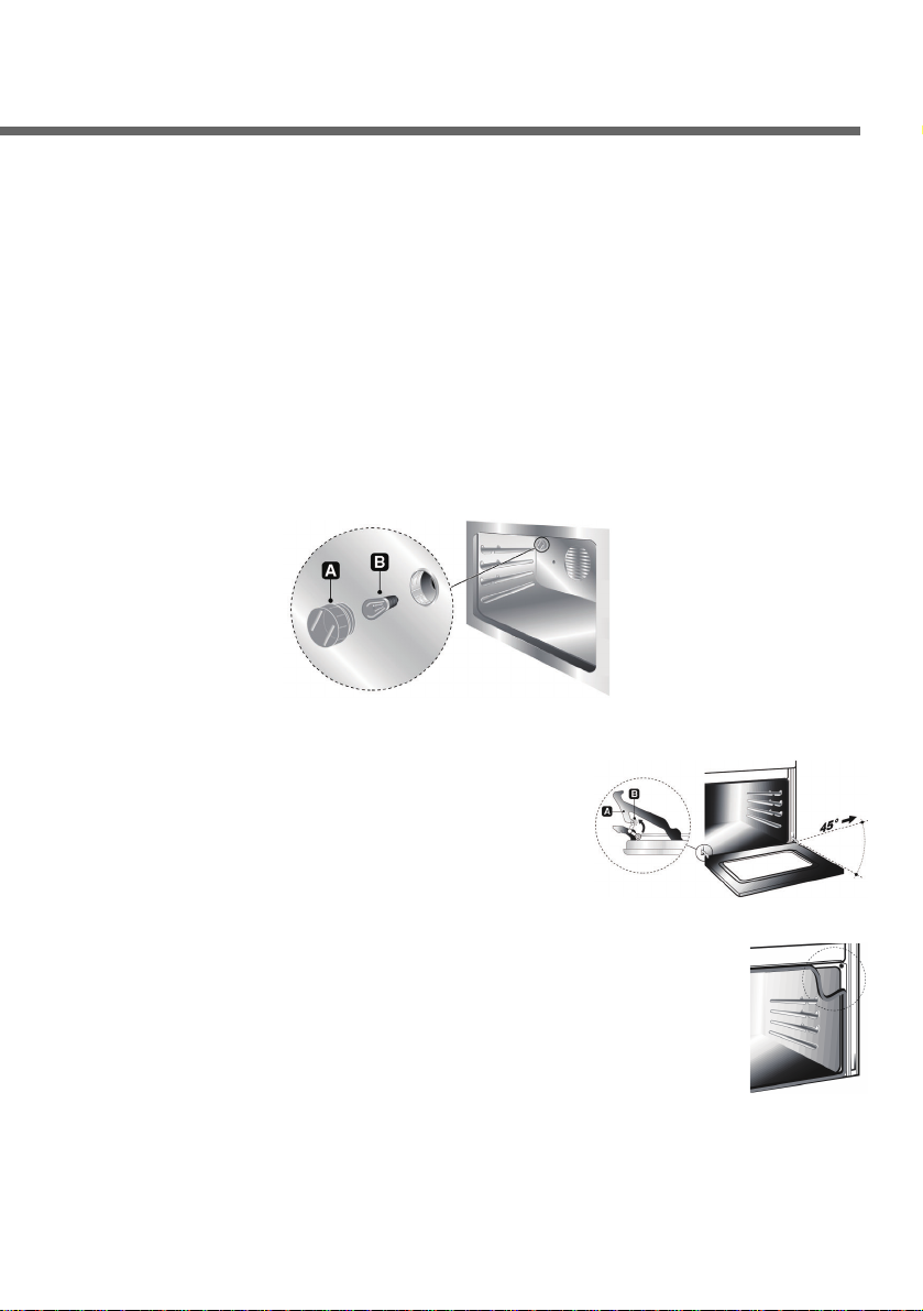
11. Extraordinary maintenance
The oven may require extraordinary maintenance or replacement of
parts subject to wear such as seals, bulbs, and so on. The following
instructions describe how to carry out these minor maintenance
operations.
Before any intervention, disconnect the power supply of the
device.
11.1 Replacement of light bulb
Remove cover A by twisting anticlockwise, replace bulb B with
another similar bulb (25 W).
Refit the cover A.
Only use oven bulbs (T 300°C).
11.2 Removing the door
Hold the door on both sides with both hands
near hinges A and raise levers B. Lift up the
door forming an angle of about 45° and
remove. To refit, slide the hinges A in the
grooves, drop the door and release levers B.
11.3 Oven door seal
To permit thorough cleaning of the oven, the seal may
be removed. Before removing the seal, take off the door
as described above. Once the door has been taken off,
lift the tabs at the corners as shown in the figure.
11.4 Lubrication of the taps
In time the taps may be difficult to turn or may be blocked. Clean
them inside and replace the lubrication grease. This operation
should be carried out by a specialised technician.
Page 34

Page 35

Page 36

FOR WARRANTY SERVICE PLEASE CONTACT
LG Service on 1300 LG CARE (1300 54 2273) AUSTRALIA or
0800 LG CARE (0800 54 2273) NEW ZEALAND
LG Electronics Australia
2 Wonderland Drive
Eastern Creek NSW 2766
(ABN : 98 064 531 264)
LGEAP
 Loading...