

Page 1

Libretto di Istruzioni
Instructions Manual
Manuel d’Instructions
Bedienungsanleitung
Gebruiksaanwijzing
Manual de instrucciones
Manual
de
Instru
çõ
es
Bruksanvisning
ɋɮɥɩɝɩɟɬɭɝɩ ɪɩ ɸɥɬɪɦɮɛɭɛɱɣɣ
KR37X
Page 2

INDICE
CONSIGLI E SUGGERIMENTI ..............................................................................................................................................4
CARATTERISTICHE..............................................................................................................................................................5
INSTALLAZIONE....................................................................................................................................................................6
USO......................................................................................................................................................................................10
MANUTENZIONE.................................................................................................................................................................11
IT
INDEX
RECOMMENDATIONS AND SUGGESTIONS....................................................................................................................13
CHARACTERISTICS............................................................................................................................................................14
INSTALLATION ....................................................................................................................................................................15
USE.......................................................................................................................................................................................19
MAINTENANCE....................................................................................................................................................................20
SOMMAIRE
CONSEILS ET SUGGESTIONS ..........................................................................................................................................22
CARACTERISTIQUES.........................................................................................................................................................23
INSTALLATION ....................................................................................................................................................................24
UTILISATION........................................................................................................................................................................28
ENTRETIEN..........................................................................................................................................................................29
INHALTSVERZEICHNIS
EMPFEHLUNGEN UND HINWEISE....................................................................................................................................31
CHARAKTERISTIKEN..........................................................................................................................................................32
MONTAGE............................................................................................................................................................................33
BEDIENUNG.........................................................................................................................................................................37
WARTUNG............................................................................................................................................................................38
INHOUDSOPGAVE
ADVIEZEN EN SUGGESTIES.............................................................................................................................................40
EIGENSCHAPPEN...............................................................................................................................................................41
INSTALLATIE .......................................................................................................................................................................42
GEBRUIK..............................................................................................................................................................................46
ONDERHOUD ......................................................................................................................................................................47
EN
FR
DE
NL
ÍNDICE
CONSEJOS Y SUGERENCIAS ...........................................................................................................................................49
CARACTERÍSTICAS............................................................................................................................................................50
INSTALACIÓN......................................................................................................................................................................51
USO......................................................................................................................................................................................55
MANTENIMIENTO................................................................................................................................................................56
ES
2
2
Page 3

ÍNDICE
CONSELHOS E SUGESTÕES............................................................................................................................................58
CARACTERÍSTICAS............................................................................................................................................................59
INSTALAÇÃO.......................................................................................................................................................................60
UTILIZAÇÃO.........................................................................................................................................................................64
MANUTENÇÃO....................................................................................................................................................................65
PT
ɎɅȻɂȻɍɀɆɗ
ɋɈȼȿɌɕ ɂ ɊȿɄɈɆȿɇȾȺɐɂɂ...........................................................................................................................................67
ɏȺɊȺɄɌȿɊɂɋɌɂɄɂ.............................................................................................................................................................68
ɍɋɌȺɇɈȼɄȺ........................................................................................................................................................................69
ɗɄɋɉɅɍȺɌȺɐɂə.................................................................................................................................................................73
ɍɏɈȾ ....................................................................................................................................................................................74
INNEHÅLL
REKOMMENDATIONER OCH TIPS....................................................................................................................................76
EGENSKAPER.....................................................................................................................................................................77
INSTALLATION ....................................................................................................................................................................78
ANVÄNDING.........................................................................................................................................................................82
UNDERHÅLL........................................................................................................................................................................83
RU
SE
3
3
Page 4
EN
1
RECOMMENDATIONS AND SUGGESTIONS
The Instructions fo r Use apply to several versi ons of this a ppliance. Acco r
d-
ingly, you may find descriptions of individual features that do not apply to your
specific appliance.
INSTALLATION
• The man ufa ctu re r will n ot be held liable for any damages resulting from incorrect or impr op er ins ta ll a tio n.
• The mini mum safet y dista nc e betw een t he c ooker top a nd th e ext rac tor h ood
is 650 mm (some models c an be installed a t a lower height, ple ase refer to
the paragraphs on working dimensions and installation).
• Check t ha t th e m ains voltage corresponds to that indicated on the rating plat e
fixed to the inside of the hood.
• For Class I appliances, check tha t the domestic power supply gua rantees
adequate earthing.
Connect the extractor to the exhaust flue through a pip e of m ini m um diam eter
120 mm. The route of the flue must be as short as possible.
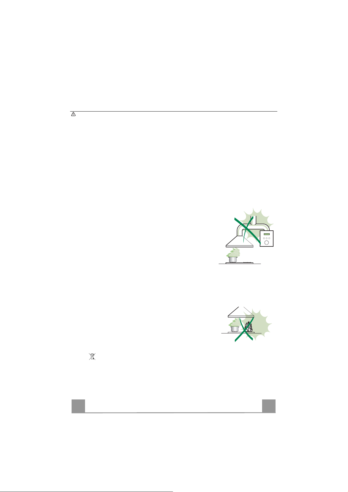
• Do not connect the extractor hood to exhaust ducts carrying combustion
fumes (boilers, fireplaces, etc.).
• If the extractor is used in conj unction with n on-electrical appliances ( e.g. gas
burning applianc es) , a s uffi ci e nt de gr ee of aeration must be guaranteed i n th e
room in order to preve nt the backfl ow of exh aust g as. T he kitch en mu st hav e
an opening communi cating directly with the ope n air in order to guarantee the
entry of clean air.
USE
• The extractor hood has been de signed exclusiv ely for domestic use to elim inate kitchen smells.
• Never use the hood for purposes other than for which it has been designed.
• Never lea ve high na ke d fla me s un der the ho od wh en it is in op erat i on .
• Adjust the flame i ntensity to di rect it onto the bott om of the pan onl y, making
sure that it does not engulf the sides.
• Deep fat f ryers must be continuously monitore d during use: overheated oil
can burst into flames.
• Do not flambè under the range hood; risk of fire
• This a ppliance is not intended for use by persons (includi ng children) with
reduced physical, sensory or mental capabilities, or lack of experience and
knowledge, unless they have been given supervision or instruction concerning
use of the appliance by a person responsible for their safety.
• Children should be supervised to ensure that they do not play with the appliance.
MAINTENANCE
• Switch of f or u nplug th e appl iance f rom the mains s upply before carryin g out
any maintenance work.
• Clean and/or replace the Filters after the specified time period (Fire hazard).
• Clean the hood using a damp cloth and a neutral liquid detergent.
The symbol on the product or on its packaging indicates that this product may not be treated
as household waste. Instead it shall be handed over to the applicable collection point for the recycling of elec trical and electr onic eq uipme nt. By e nsurin g this pro duct is dis pose d of correc tly, yo u
will help prevent potential negative consequences for the environment and human health, which
could otherwise be caused by inappropriate waste handling of this product. For more detailed
informati on about r ecycling of this product, pl ease co ntact yo ur local ci ty offic e, your h ousehold
waste disposal service or the shop where you purchased the product.
13
Page 5

EN
1
CHARACTERISTICS
Dimensions
540
Min.
550mm
Min.
550mm
Components
Ref. Q.ty Product components
1 1 Hood equipped with: Controls, Lights, Filters
3 1 Hood sup port equipped with the Exhaust Group
7 1 tube in PVC
8 1 Directioned grid
8c 1 Air outlet r eduction ø 120mm
9 1 Reduction flange ø 150-120 mm
Ref. Q.ty Installation components
11 4 Small blocks ø 10
12a 4 Screws 5 x 70
12b 4 Sc rews M4 x 15
12e 2 Screws 2,9 x 9,5
13 4 Screws pl ug M4
Q.ty Documentations
1 Instruction booklet
12e
8
8c
13
7
9
12b
1
11
12a
3
14
Page 6

EN
1
INSTALLATION
Wall drilling and bracket fixing
100 100
170
175
11
12a
100 100
1240
1050 390
When installing the hood in recyclin g version it has to be taken into consideration th at space remaining between the hood and the upper limit (ceiling or self) is at least 8-10 cm.
On the wall, draw:
• a Vertical line up to the ceiling or upper limit, at the centre of the area in which the hood is
to be fitted;
• a Horizontal line at a minimum of 1050 mm above the Cooker Top; .
• As indi cat ed, mark a reference point at 100 mm to the right of th e vertical reference line.
• Repeat this operation on the other side, checki ng that the two marks are level.
• As indi cated, mark a reference point at 390 mm above the horizontal reference line, and at
100 mm to the right of the vertical reference line.
• Repeat this operation on the other side, checki ng that the two marks are level.
• Drill at the points marked, using a ø 10 mm drill bit.
• Insert the plugs 11 into the holes.
15
Page 7

EN
1
Hood support mounting
• Lean the hood support 3 against the wall making sure that
holes in the hood support correspond to those in the wall.
• Block the hood support to the wall using 4 12a (5 x 70) screws
supplied with the hood.
• Before fastening the screws definitively make sure that the
support is well-levelled. Only after this operation proceed with
the definitive tightening of the screws.
Air outlet connection in the ducting version
When installing the hood in ducting version, basing on the installer’s choice, a rigid or a flexible pipe with a ø 150 o 120 mm
is used in order to connect the hood to the air outlet piping. The
pipe connection can be made on the upper part or on the back
side of the hood.
AIR OUTLET ON THE BACK SIDE OF THE HOOD
• When drilling the air outlet hole in the wall proceed in accordance with the scheme in the paragraph concerning the wall
drilling.
• In case the connection is made with a ø 120 mm pipe insert the
reduction flange 9 on the hood body outlet.
• Fix the pipe with an adequate quantity of pipe clamps. This
material is not supplied together with the hood.
• Remove the charcoal filter if present.
AIR OUTLET ON THE UPPER PART OF THE HOOD
• In case the connection of the hood to the air outlet piping is
made with a ø 150 mm pipe then use a rigid or a flexible pipe.
• In case the connection is made with a ø 120 mm pipe insert the
reduction flange 9 on the hood body outlet.
• Fix the air outlet reduction 8c to the air outlet hole of the hood
support with the screws supplied together with the hood.
• Connect the hood to the piping with a rigid or a flexible pipe.
• Fix the pipe with an adequate quantity of pipe clamps. This
material is not supplied together with the hood.
• Remove the charcoal filter if present.
12a
3
8c
ø 120
9
ø 150
16
Page 8

EN
1
RECIRCULATION VERSION AIR OUTLET
• Insert pvc pipe 7 provided onto the Hood Canopy Outlet.
.
Hood body mounting
Ducting version
• In case the air outlet conn ection on the upper part of th e hood
has been chosen it will be necessary to remove the pre-cut
piece.
• Lean the hood body on the support and fix it laterally with the
4 12b screws.
• Cover the screw seats with the plugs 13 supplied with the
hood.
ø 150
7
Recycling version
• Remove the pre-cut piece.
• Lean the hood body on the support and fix it laterally with the
4 12b screws.
• Cover the screw seats with the plugs 13 supplied with the
hood.
• Place th e d irecti oned grid 8 on the pipe and make sure that it is
correctly installed.
• Fix the directioned grid 8 with the screws 12e supplied together with the hood.
• Make sure that the charcoal filters are present.
13
12b
12e
8
17
Page 9

EN
1
ELECTRICAL CONNECTION
• Connect the hood to the mains through a twopole
switch having a contact gap of at least 3 mm.
• Open the lighting unit by pulling on the notch.
• Re move the filters one at a time by pushing them towards the
back of the group and pulling down at the same time.
• Being sure that the co nnector of the feeding cable i s correctly
inserted in the socket placed on the side of the fan.
• Con nect the control connector Cmd.
• Connect the Spotlights connector Lux to the socket provided
behind the l ighting unit cover.
Lux
• Replace the filters, make sure that the handle is visible on the
outside, and the lighting unit.
Cmd
18
Page 10

EN
1
USE
L
T1
T2
T3
T4
L1
L2
L3
L4
Control panel
Button Function Led
L Press briefly to turn the lighting system on and off.
Press and hold for app rox. 2 secon d s to tu rn the li ght in g system on and
off at reduced intensity.
T1 Turn the suction motor on and off at speed one.
If the filter saturation alarm is on, this resets it.
T2 Turn the suction motor on at speed two.
If the filter saturation alarm is on, this resets it.
T3 Press once to turn the suction motor on and off at speed th r ee.
Press again to activate intensive speed. This speed is timed to run for
10 minutes. At the end of this time the system will automatically return
to the speed set before.
Suitable to deal with maximum levels of cooking fumes, it is deactivated by pressing any one of the Speed buttons (T1-T2-T3).
It cannot be activated if the Delay function is in use.
If the filter saturation alarm is on, this resets it.
Activate automatic switch-off with a 30’ delay (Motor+Lights).
T4
Suitable to complete elimination of residual odours.
Can be activated from any Speed, and is disabled by pressing the
button again or turning the motor off.
It cannot be activated if the Intensive function is in use.
If the filter saturation alarm is on, this resets it.
-
On.
On.
On.
Flashing.
On.
Warning: The working hours of the mot or are counted for the purpose of signalling filter saturation.
After 100 working hours all the LEDs (L1-L2-L3-L4) will light up and remain lit to indicate saturation of
the metal grease filters.
After 200 working hours all the LEDs (L1-L2-L3-L4) will light up and start to flash to indicate saturation
of the activated charcoal filters.
19
Page 11

EN
2
MAINTENANCE
Metal grease filters
These can also be washed in the dishwasher, and need to be
cleaned when all the command LEDs light up in a continuous
manner or at least once every 2 months use, or more frequently if
use is particularly intensive.
Resetting the alarm signal
• Press any of the buttons except the Light button.
Cleaning the Filters
• Open the lighting unit by pulling on the nocth.
• Remove the Filters one at a time, pushing them towards the
back of the unit and at the same time pulling downward.
• Wash the Filters without bending them, and leave them to dry
completely before replacing.
• Replace, taking care to ensure that the handle faces forwards.
• Replace the lighting unit.
20
Page 12

EN
2
Activated Charcoal Filter (Recirculation Version)
• This cannot be washed or regenerated, and must be changed when all the command LEDs
start to flash, or at least on ce every 4 months.
Activating the alarm signal
• In Recirculation Version Hoods, the Filter Saturation Alarm must be activated on installation or at
a later d a te .
• Press and hold the Delay button (T4) on the keypad for 5 s econds and the following will be displayed:
• Leds (L1-L2-L3) flash twice – Activated Charcoal Filter saturation alarm ACTIVATED.
• Leds (L1-L2-L3) flash once – Activated Charcoal Filter saturation alarm DEACTIVATED.
CHANGING THE ACTIVATED CHARCOAL FILTER
Resetting the alarm signal
• Press any of the buttons except the Light button.
Changing the Filter
• Open the lighting unit by pulling on the nocth.
• Remove the Metal grease filters.
• Remove the saturated Activated Charcoal filter, as shown in
the figure.
• Fit the new Filter, hooking it into place.
• Replace the M etal grease filters.
• Replace the lighting unit.
Lighting
LIGHT REPLACEMENT
20 W halogen light.
• Extract the lamp from the lamp holder by pulling gently.
• Replace with another of the same type, making sure that the
two pins are properly inserted in the lamp holder socket holes.
21
 Loading...