

Page 1

Libretto di Istruzioni
Instructions Manual
Manuel d’Instructions
Bedienungsanleitung
Gebruiksaanwijzing
Manual de instrucciones
Manual de Instruções
KIV90X
Page 2

INDICE
CONSIGLI E SUGGERIMENTI ..............................................................................................................................................4
CARATTERISTICHE..............................................................................................................................................................5
INSTALLAZIONE....................................................................................................................................................................7
USO......................................................................................................................................................................................11
MANUTENZIONE.................................................................................................................................................................12
IT
INDEX
RECOMMENDATIONS AND SUGGESTIONS....................................................................................................................14
CHARACTERISTICS............................................................................................................................................................15
INSTALLATION ....................................................................................................................................................................17
USE.......................................................................................................................................................................................21
MAINTENANCE....................................................................................................................................................................22
SOMMAIRE
CONSEILS ET SUGGESTIONS ..........................................................................................................................................24
CARACTERISTIQUES.........................................................................................................................................................25
INSTALLATION ....................................................................................................................................................................27
UTILISATION........................................................................................................................................................................31
ENTRETIEN..........................................................................................................................................................................32
INHALTSVERZEICHNIS
EMPFEHLUNGEN UND HINWEISE....................................................................................................................................34
CHARAKTERISTIKEN..........................................................................................................................................................35
MONTAGE............................................................................................................................................................................37
BEDIENUNG.........................................................................................................................................................................41
WARTUNG............................................................................................................................................................................42
INHOUDSOPGAVE
ADVIEZEN EN SUGGESTIES.............................................................................................................................................44
EIGENSCHAPPEN...............................................................................................................................................................45
INSTALLATIE .......................................................................................................................................................................47
GEBRUIK..............................................................................................................................................................................51
ONDERHOUD ......................................................................................................................................................................52
EN
FR
DE
NL
ÍNDICE
CONSEJOS Y SUGERENCIAS ...........................................................................................................................................54
CARACTERÍSTICAS............................................................................................................................................................55
INSTALACIÓN......................................................................................................................................................................57
USO......................................................................................................................................................................................61
MANTENIMIENTO................................................................................................................................................................62
ES
2
2
Page 3

EN
1
RECOMMENDATIONS AND SUGGESTIONS
The Instructions for Us e appl y to s everal ver sions of this appli anc e. Acco r
d-
ingly, you may find descrip tions of individual featur es that do not apply to
your specific appliance.
INSTALLATION
• The manufacturer will not b e held liable for an y damages resulting fr om incorrect or i mpr op er in sta l lat ion .
• The minimum safety distance between the cooker top and the extractor
hood is 650 mm (som e m od el s can be installed at a low er height, please refer to the paragraphs on working dimensions and installation).
• Check th at the mains voltage corres ponds to that indicated on the rating
plate fixed to the inside of the hood.
• For Class I appliances, check that t he domestic power supply guar antees
adequate earthing.
Connect the extractor t o the e xhaus t flu e throu gh a pipe o f mi nimum diame-
ter 120 mm. The route of the flue must be as short as possible.
• Do not conn ect the extractor hood to exhaus t ducts carrying combustion
fumes (boilers, fireplaces, etc.).
• If the ext ra cto r i s used in conjunction with non-electrical appliances (e.g. gas
burning applia nces), a suffici ent degree of aeration must be guaranteed i n
the room in order to prevent t he backfl ow of exha ust gas. T he kitch en must
have an opening communica ting dir ectly with t he open air in ord er to gua rantee the entry of clean air.
USE
• The extractor hood has been designed exclusively for domestic use to eliminate kitchen smells.
• Never use the hood for purposes other than for which it has been designed.
• Never leave high naked fla me s un der the ho od wh en it is in oper at i on.
• Adjust th e flame intensity to direct it onto the bottom of the pan only, maki ng
sure that it does not engulf the sides.
• Deep fat fryers must b e continuously m onitored durin g use: overhe ated oil
can burst into flames.
• Do not flambè under the range hood; risk of fire
• This appliance is not intended for use by persons (includi ng children) with
reduced physical, se nsory or mental capabilities, or la ck of experience an d
knowledge, unless th ey have been g iven su pervisi on o r instr uction conce rning use of the appliance by a person responsible for their safety.
• Child re n sh ould be supervised to ensur e that they do not play with the appli ance.
MAINTENANCE
• Switch off or unplug the appliance fr om the m ai ns s up ply be fo re ca rr yi n g ou t
any maintenance work.
• Clean and/or replace the Filters after the specified time period (Fire hazard).
• Clean the hood using a damp cloth and a neutral liquid detergent.
650 mm min.
The symbol on the product or on its packaging indicates that this product may not be treated
as household waste. Instead it shall be handed over to the applicable collection point for the
recycling of electrical and electronic equipment. By ensuring this prod uct is disposed of correctly,
you will help prevent potential negative consequences for the environment and human health,
which could otherwise be caused by inappropriate waste handling of this product. For more
detailed information about recycling of this product, please contact your local city office, your
household waste disposal service or the shop where you purchased the product.
14
Page 4
EN
1
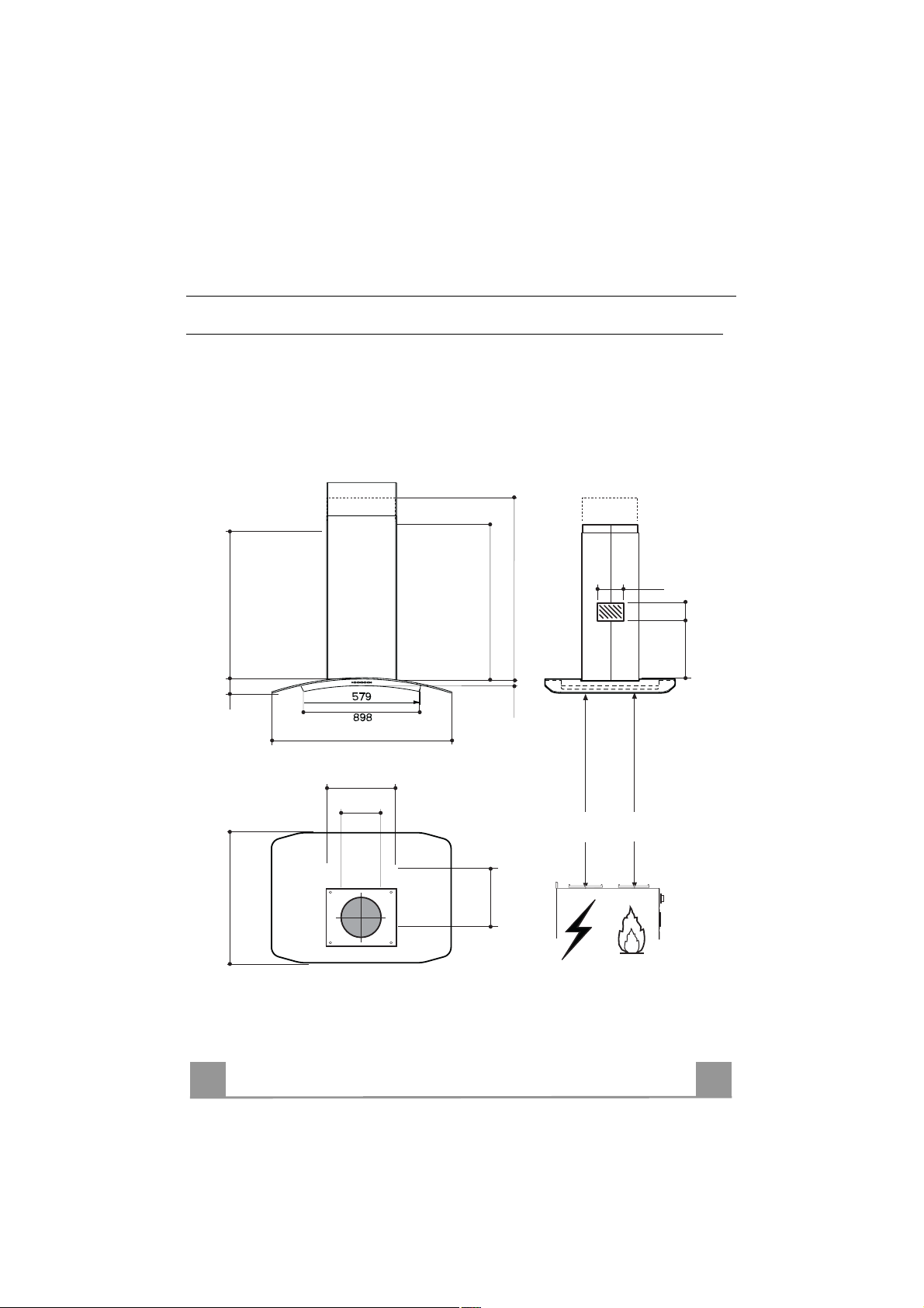
CHARACTERISTICS
Dimensions
700
70
650
350
150
Max
Min 780
290
1070
36
Min.
500mm
132
90
310
Min.
650mm
15
Page 5

EN
1
Components
Ref. Q.ty Product Components
1 1 Hood Canopy c omplete with: Controls, Lights, Filters
2 1 Telescopic chimney made u p of:
2.1 1 Upper chimney
2.2 1 Lower chimney
7.1 1 Telescopic frame complete with Suction fan, made up
of:
7.1a 1 Upper frame
7.1b 1 Lower frame
8a 1 Rh Air Outlet Directional Grille
8b 1 Lh Air Outlet Directional Grille
9 1 Reduction flange ø 150-120 mm
14.1 1 Air Outlet C onnector Exte nsion
15 1 Air Outlet Connector
24 1 Connection box
25 Pipe clamps (not included)
26 2 Cable clamps
27 1 Finishing plug
Ref. Q.ty Installation Components
11 4 Wall Plugs ø 10
12c 6 Screws 2,9 x 6, 5
12e 2 Screws 2,9 x 9, 5
12f 2 Screws M4 x 80
12g 4 Screws M6 x 80
12h 4 Screws 5,2 x 70
12q 4 Screws 3,5 x 9,5
21 1 Drilling template
22 8 6.4 mm int. dia washers
23 4 M6 nuts
Q.ty Documentation
1 Instruct ion booklet
21
22
7.1a
12g
7.1
7.1b
12c
2.1
2
2.2
8b
12c
1
12f
22
12q
23
11
12h
15
14.1
9
25
26
27
8a
12e
24
12c
16
Page 6

EN
1
INSTALLATION
Drilling the Ceiling/shelf and fixing the frame
DRILLING THE CEILING/SHELF
• Use a plumb line to mark the centre of the hob on the ceiling/support shelf.
• Place the drilling template 21 provided on the ceiling/support shelf, making sure that the
template is in the correct position by lining up the axes of the template with those of the hob.
• Mark the centres of the holes in the template.
• Drill the holes at the points marked:
• For concrete ceilings, drill for plugs appropriate to the screw size.
• For hollow brick ceilings with wall thickness of 20 mm: drill ø 10 mm(immediately insert
the Dowels 11 supplied).
• For wooden beam ceilings, drill according to the wood screws used.
• For wooden shelf, drill ø 7 mm.
• For the power supply cable feed, drill ø 10 mm.
• For the air outlet (Ducted Version), drill according to the diameter of the external air exhaust duct connection.
• Insert two screws of the following type, crossing them and leaving 4-5 mm from the ceiling:
• For concrete ceilings, use the appropriate plugs for the screw size (not provided).
• for Cavity ceiling with inner space, with wall thickness of approx. 20 mm, Screws 12h,
supplied.
• For wooden beam ceilings, use 4 wood screws (not provided).
• For wooden shelf, use 4 screws 12g with washers 22 and nuts 23, provided.
17
Page 7

EN
1
Fixing the frame
• Loosen the two scr ews fastening the lower chimney an d remove this from the lower frame.
• Loosen the two screws fastening the upper chimney and remove this from the upper frame.
If you wish to adjust the height o f the frame, proceed as follows:
• Unfasten the metric screws joining the two columns, located at
the sides of the frame.
• Adjust the frame to the height required, then refit all the screws
removed as above.
• Insert the upper chimney stack from above, and leave it running free on the frame.
• Lift up the frame, fit the frame slots onto the screws up to the
slot end positions.
• Tighten the two screws and fasten the other two screws provided with the hood.
Before tightening the screws completely it is possible to adjust
the frame by turning it. Make sure that the screws do not come
out of their seats in the slotted holes.
• The frame mountings must be secure to withstand the weight
of the hood and any stresses caused by the occasional side
thrust applied to the device.
On completion, check that the base is stable, even if the frame
is subjected to bending.
• In all cases where the ceiling is not strong enough at the suspension point, the installer must provide strengthening using
suitable plates and backing pieces anchored to the structurally
sound parts.
1
2
1
2
Ducted version air exhaust system Connection
When installing the ducted version, connect the hood to the
chimney using either a flexible or rigid pipe ø 150 or 120 mm,
the choice of which is left to the installer.
• To install a ø 120 mm air exhaust connection, insert the reducer flange 9 on the hood body outlet.
• Fix the pipe using the pipe clamps 25 (not provided).
• Remove any activated charcoal filters.
ø 150
ø 120
25
25
9
18
Page 8

EN
1
RECIRCULATION VERSION AI R OUTLET
14
• Assemble the two halves o f the hood bod y extension piece 14
(if necessary).
• Push fit the assembled h ood body extension piece 14 onto the
air outlet (if necessary).
• Push fit connect ion 15 onto the hood body extension p iece
or directly onto the hood body.
• Insert the connection extension pieces laterally 14.1 in connection 15.
Should the central rei nforcing pi ece of the frame somehow i nterfere the chimney air outlet grille, it is possible to unscrew it and
to place it in another screw hole set.
14.1
15
14
Flue assembly - Mounting the hood body
• Position the upper chimney section and fix the upper part to the
frame using the 2 screws 12c (2,9 x 6,5) provided.
• Similarly, position the lower chimney section and fix the
lower part to the frame using the 2 screws 12c (2,9 x 6,5) provided.
Recirculation version
• Make su re that the outlet of the extension pieces 14.1 is horizontally and vertically aligned with the chimney outlets.
• Otherwise, re move the lower chimney and adju st the position
by inverting the extensi on pieces for ai r outlet co nnection 14.1
or by cutting the hood body extension piece 14 (if any) along
one of the chases destined to the predetermined extension
lengths. Replace then the elements as earlier described.
• Fit the directional grids 8a - 8b in their housings making sure
that the directional symbols are towards the top. Also make
sure that they are correctly inserted in the connection extension pieces 14.1.
Before fixing the hood canopy to the frame:
• Screw the 2 screws 12f half way into the holes provided in the
sides of the bottom of the frame.
• Remove the grease filters from the hood canopy.
• Remove any activated charcoal filters.
• Lift the hood canopy and engage the screws 12f in the slots (A)
as far as they will go.
• Working from below, fix the hood canopy to the frame (B),
using the 4 screws 12q and 4 washers 22 provided, then tighten
all the screws securely.
12c
8b
12c
12f
12q
A
8a
22
B
19
Page 9

EN
2
ELECTRICAL CONNECTION
• Connect the Hood to th e Mains power supply, inserting a two-pole Switch with a contact aperture of at least 3 mm.
• Remove the Metal grease filters (see par.
on “Maintenance”) and make sure that the
power supply Cable is properly inserted in
the Suction fan socket.
• Take the wire s indicated in fig.1 and pass
them through the slot formed on the galvanized diffuser support, as shown in fig.2.
1
2
• Position the finishing plug 27 over the
housing in the diffuser support, fixing it using a screw 12e (2.9 x 9.5) and applying the
2 cable clamp elements 26 as i ndicated in
figs. 3 and 4.
• Connect the Controls Connector fig. 5.
• Con nect the Lighting Connector fig. 6.
• Store both the Connect ors in the Protective
box 24 and clo se it with 2 Screws 12e (2.9
x 9.5), provided.
• Remove the protective film from the double-sided adhesive on the connection box,
and fix it inside the motor compartment fig.
7.
34
6
5
7
20
Page 10

EN
2
USE
L1 L2 L3 L4
L T1 T2 T3 T4
Control panel
Button Function Led
L Press briefly to turn the lighting system on and off.
Press and hold for app rox. 2 seconds to turn the light ing system
on and off at reduc ed intensity.
T1 Turn the s u ction motor on and off at speed one.
If the filter saturation alarm is on, this resets it.
T2 Turn the s u ction motor on at speed two.
If the filter saturation alarm is on, this resets it.
T3 Press once to turn the suction motor on and off at speed three.
Press again to activate intensive speed. This speed is timed to run
for 10 minutes. At the end of this time the system will
automatically return to the speed set before.
Suitable to deal with maximum levels of cooking fumes, it is deactivated by pressing any one of the S peed buttons (T1-T2-T3).
It cannot be activated if the Delay function is in use.
If the filter saturation alarm is on, this resets it.
Activate automatic switch-off with a 30’ delay (Motor+Lights).
T4
Suitable to complete elimination of residual odours.
Can be activated from any Speed, and is disabled by pressing the
button again or turning the motor off.
It cannot be activated if the Intensive function is in use.
If the filter saturation alarm is on, this resets it.
-
On.
On.
On.
Flashing.
On.
Warning: The working hours of the motor are counted for the purpose of signalling filter
saturation.
After 100 working hours all the LEDs (L1-L2-L3-L4) will light up and remain lit to indicate
saturation of the metal grease filters.
After 200 working hours all the LEDs (L1-L2-L3-L4) will light up and start to flash to indicate
saturation of the activated charcoal filters.
21
Page 11

EN
2
MAINTENANCE
Metal grease filters
These can also be washed in the dishwasher, and need to be
cleaned when all the command LEDs light up in a continuous
manner or at least once every 2 months use, or more frequently if
use is particularly intensive.
Resetting the alarm signal
• Press any of the buttons except the Light button.
Cleaning the Filters
• Remove the Filters one at a time, pushing them towards the
back of the unit and at the same time pulling downward.
• Wash the Filters without bending them, and leave them to dry
completely before replacing.
• Replace, taking care to ensure that the handle faces forwards
22
Page 12

EN
2
Activated Charcoal Filter (Recirculation Version)
• This cannot be washed or regenerated, and must be changed when all the command LEDs
start to flash, or at least on ce every 4 months.
Activating the alarm signal
• In Recirculation Version Hoods, the Filter Saturation Alarm must be activated on installation or at
a later d a te .
• Press and hold the Delay button (T4) on the keypad for 5 s econds and the following will be displayed:
• Leds (L1-L2-L3) flash twice – Activated Charcoal Filter saturation alarm ACTIVATED.
• Leds (L1-L2-L3) flash once – Activated Charcoal Filter saturation alarm DEACTIVATED.
CHANGING THE ACTIVATED CHARCOAL FILTER
Resetting the alarm signal
• Press any of the buttons except the Light button.
Changing the Filter
• Remove the Metal grease filters.
• Remove the saturated Activated Charcoal filter, as shown in
the figure.
• Fit the new Filter, hooking it into place.
• Replace the M etal grease filters.
Lighting
LIGHT REPLACEMENT
20 W halogen light.
• Remove the snap-on lamp cover by levering it from under the
metal ring, supporting it with one hand.
• Remove the halogen lamp from the lamp holder by pulling
gently.
• Replace the lamp with a new one of the same type, making
sure that you insert the two pins properly into the housings on
the lamp holder.
• Replace t he snap-on lamp cover.
23
 Loading...