

Page 1
installation
smeg
technology with style
���
�
�
�
and operating
instructions
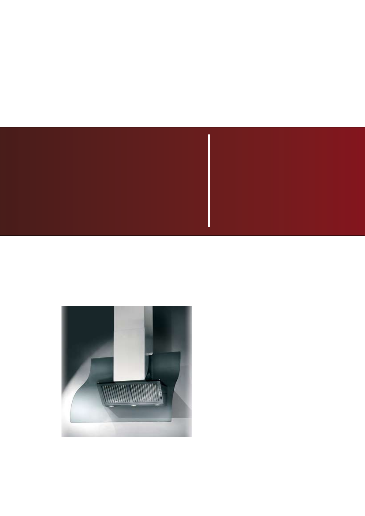
K280
rangehood
Page 2

ENGLISH
DESCRIPTION
The hood may be in the filtering or the ducting version.
Filtering version (Fig. 1): The hood aspirates the kitchen air saturated with fumes and odours, purifies it through
the grease filter/s and charcoal filter and returns clean air into the room. For constant efficiency, the charcoal filter must
be replaced periodically. The charcoal filter is not supplied.
Ducting version (Fig. 2): The hood aspirates the kitchen air saturated with fumes and odours, passes it through the
grease filter/s and expels it to the outside through an outlet pipe. With this version the charcoal filter is not required. Decide
from the outset on the type of installation (filtering or ducting). For greater efficiency, we recommend you install the hood
in the ducting version (if possible).
INSTALLATION
ATTENTION: Two persons are required for proper installation; the unit should be installed by a qualified operator.
1. Before proceeding with the installation operations, remove the grease filters to make it easier to handle the hood:
grip the knob and push it towards the opposite side of the filter and turn the filter outwards (Fig. 3).
2. Fixing to the wall: Draw a line on the wall along the vertical axis of the hob. Mark the first 2 holes to be drilled
on the wall, respecting the measurements indicated in Fig. 4; drill the 2 holes and insert the screw anchors (provided).
Bear in mind that the distance between the lower edge of the hood (the part where the lamps are positioned) and the hob
must be at least 650 mm. Fix the metal bracket (A) to the wall using the 2 holes just drilled - Fig. 5 - (the bracket retaining
screws are not provided). Use the 2 triangles cut into the bracket to position it exactly along the vertical axis of the hood.Then
hook the hood onto the bracket (Fig. 6). Adjust the horizontal position by moving the hood to the right or left according
to the wall unit alignment. If the hood needs to be adjusted in height, operate on the adjusting screws (B) (provided). Once
adjusted, without removing the hood, mark the other 4 holes to be drilled on the wall (C); unhook the hood and drill the
holes marked (8 mm diameter); then use the 4 screw anchors and 4 screws provided for final fixing.
3. Fit the electrical system plate, securing it with 2 screws (V) and 2 washers (Fig. 7).
INSTALLATION IN DUCTING VERSION:
Before fixing, the outlet pipe for air evacuation to the outside must be installed. Use an outlet pipe with: – minimum
indispensable length; – minimum possible bends (maximum angle of bend: 90°); – certified material (according to the State);
– an as smooth as possible inside. It is also advisable to avoid any drastic changes in pipe cross-section (recommended
diameter: 150 mm). For air evacuation to the outside, follow all the other instructions given on the “Warnings” sheet. Prepare
the power supply within the telescopic chimney (for the electrical connection, follow all the other instructions on the
“Warnings” sheet).
4. Fitting the telescopic flues:
- Adjust the width of the telescopic flue support bracket (D) using the screws F indicated in Fig. 8.
- Then, using the screw anchors and the screws (G) provided, fit the bracket to the ceiling in such a way that it is in line
with the hood (Fig. 8).
- Fit the 2 glass stops to the sides of the lower flue: screw in the screw working from the inside of the lower flue an lock
the glass stop (Fig. 9).
- Connect the air exhaust pipe to the air vent using a metal clamp (pipe and clamps not provided).
- Make the electrical connection of the hood by means of the power cable.
- Fit the telescopic flues resting them on the hood; raise the upper flue as far as the ceiling and secure it with the 2 screws
H (Fig.10).
- Secure the lower flue with 4 screws, working from the inside of the hood (Fig. 11).
- In the ducting version, the charcoal filter is not required; therefore if it has been installed, remove it by pushing the catch
inwards and turning the filter downwards until the 2 clips slip out of their seats (Fig. 12).
5. Fitting the grease drip trays: position the 2 drip trays inside the hood in proximity of the halogen lamps and move
the trays sideways towards the outside of the hood (Fig. 13).
6. Fitting the glass panel: Fit the 2 plastic strips on the upper edge of the glass panel (Fig. 14); Position the glass
panel in the 2 glass stops and secure it to the hood with 2 screws and 4 washers (Fig. 14).
INSTALLATION IN FILTERING VERSION:
Prepare the power supply within the telescopic flues (for the electrical connection, follow all the other instructions on the
“Warnings” sheet).
4. Fitting the reducer: Position the reducer (R) above the air vent of the motor and exercise slight pressure (Fig.7).
5. Fitting the telescopic flues:
- Adjust the width of the telescopic flue support bracket (D) using the screws F indicated in Fig. 8.
- Then, using the screw anchors and the screws (G) provided, fit the bracket to the ceiling in such a way that it is in line
with the hood (Fig. 8).
- Take the air baffle and fit the relative flange (W) with a rotary movement (Fig. 15); Fit a flexible hose to the flange (125
mm diameter) locking it with a metal clamp (hose and clamps not provided). Secure the air baffle to the upper flue (Fig.15)
Page 3

with 4 screws.
- Fit the 2 glass stops to the sides of the lower flue: screw in the screw working from the inside of the lower flue an lock
the glass stop (Fig. 9).
- Connect the flexible hose to the reducer (R) on the air vent (Fig. 16).
- Make the electrical connection of the hood by means of the power cable.
- Fit the telescopic flues resting them on the hood; raise the upper flue as far as the ceiling and secure it with the 2 screws
H (Fig.10).
- Secure the lower flue with 4 screws, working from the inside of the hood (Fig. 11).
- In the filtering version, a charcoal filter must be used. Check if it has been installed, and if not, install it by sliding the
2 filter clips into place and turn it inwards (Fig. 12).
6. Fitting the grease drip trays: position the 2 drip trays inside the hood in proximity of the halogen lamps and move
the trays sideways towards the outside of the hood (Fig. 13).
7. Fitting the glass panel: Fit the 2 plastic strips on the upper edge of the glass panel (Fig. 14); Position the glass
panel in the 2 glass stops and secure it to the hood with 2 screws and 4 washers (Fig. 14).
OPERATION
CONTROLS (Fig. 17):
A = Light switch.
B = Motor ON/OFF - 1 speed switch
C = II speed switch
D = III speed switch
E = IV speed switch
F = Infrared beam sensor
Pressing once again the active speed switch in that moment, the timer making the apparatus stop automatically starts
working and the relative led starts to blink, this will last for 10’ then the motor will stop together with the lights (if they
are ON).
In this 10’ time it is possible to change the motor speed. If you stop the motor you stop the counting.
At the end of 30 working hours, the light switch starts blinking to indicate that the anti-grease filter needs to be cleaned.
To reset press the speed switch that was working.
Remote control working (Fig. 18):
G = Switch ON/OFF motor working at the same speed as when it had been turned OFF.
H = To increase speed
I = To lower speed
L = Light switch.
ATTENTION: the remote control needs a special care. Avoid it to come into contact with water and clean it periodically
in order to avoid any grease deposit. The remote control must be fed by a 9V, “Transistor” type battery.
To get to the battery seat, pull the cover of the remote control (as indicated in Figure 19) making it slip towards the
outside.
Get rid of the empty batteries safely, using the appropriate containers. In case you would have to eliminate the remote
control, remember that you should first take the batteries off.
Maintenance of the grease filters:
The grease filters require regular maintenance and must be cleaned on average every two months depending on use.
About every 30 hours of operation the hood signals that the grease filters need to be cleaned by the light button flashing
(Fig. 18A).
Remove the grease filters: grip the knob and push it towards the opposite side of the filter and turn the filter outwards
(Fig. 3). Wash them with a normal neutral product available on the market and then thoroughly rinse and dry them. The
filters can be washed in a dishwasher. Refit the grease filters. After cleaning the grease filters, reset the hour counter
by pressing the current operating speed button.
Maintenance of the grease drip trays:
The grease drip trays require regular maintenance and must be emptied and cleaned on average every two months depending
on use.
Removing the grease drip trays: Move the drip trays sideways towards the inside of the hood (Fig. 20) and remove them.
Maintenance of the charcoal filter:
If using a hood in the filtering version, the charcoal filter needs to be replaced on average every six months depending
on use.
To remove the charcoal filter, first remove the grease filters (Fig.21). Then remove the charcoal filter by pushing the catch
inwards and turning the filter downwards until the 2 clips slip out of their seats (Fig. 12). Replace the charcoal filter and
refit the grease filters.
Lighting:
to replace the halogen lamps, open the cover by prising in the slots (Fig. 21). Replace with lamps of the same type. WARNING:
Do not touch the new lamp with bare hands.
Page 4

1 2
3
5
4
Page 5

67
89
10
11
Page 6

12
14
13
15
16
17
E
D
C
B
A
F
Page 7

20
G
1918
H
I
L
21
Page 8

04307896 - K280-om
 Loading...