

GW6090
GW6090
GLASSWARE WASHER
- USER MANUAL -

GW6090
USER MANUAL
2
CONTENTS
1 READ THE USER MANUAL WITH CARE ....................................................................................................................... 4
2 KEY TO THE SYMBOLS USED IN THE MANUAL AND ON THE APPLIANCE ................................................................... 5
3 INTENDED USE ........................................................................................................................................................... 6
3.1 DEFINTITION: “RESPONSIBLE AUTHORITY” IN RELATION TO THE DEVICE ........................................................ 6
4 GW – MODELS ............................................................................................................................................................ 7
5 GENERAL WARNINGS ................................................................................................................................................. 8
5.1 ACCESSING AND REUSING THE DEVICE AFTER AN INCOMPLETE CYCLE ........................................................... 9
6 GENERAL OPERATING INSTRUCTIONS .................................................................................................................... 10
6.1 POWERING ...................................................................................................................................................... 10
6.2 CONTROLS ....................................................................................................................................................... 10
7 FUNCTIONING .......................................................................................................................................................... 11
7.1 HOW TO OPEN THE WASHING CHAMBER DOOR .......................................................................................... 11
7.2 DETERGENT COMPARTMENT OPENING .......................................................................................................... 12
7.3 HOW TO CONDUCT A WASHING/DISINFECTING CYCLE .................................................................................. 12
7.4 HALTING A PROGRAM IN PROGRESS ............................................................................................................. 13
7.5 PERFORMING A STAND-ALONE DRYING CYCLE ............................................................................................. 13
7.6 PRINTING OUT THE LAST CYCLE PERFORMED................................................................................................ 15
7.7 POSTPONING THE CYCLE START ..................................................................................................................... 15
7.8 SECURITY POLICY, USER AND SUPER USER PASSWORDS ................................................................................ 15
8 COMMISSIONING INSTRUCTIONS ............................................................................................................................ 17
8.1 EXTERNAL WATER SOFTENER .......................................................................................................................... 17
8.2 USING DETERGENTS ........................................................................................................................................ 17
8.2.1 LIQUID DETERGENT INTAKE SYSTEM .......................................................................................................... 17
8.2.2 GENERAL PRECAUTIONS FOR DETERGENTS ................................................................................................ 18
9 LOAD PREPARATION - GW ....................................................................................................................................... 19
10 WASHING PROGRAMS - DESCRIPTION ..................................................................................................................... 20
10.1 PARAMETRO DI TERMODISINFEZIONE A0 ....................................................................................................... 20
11 ABBREVIATIONS LEGEND ......................................................................................................................................... 21
12 ALARMS MESSAGES ................................................................................................................................................. 22
13 CLEANING AND MAINTENANCE ............................................................................................................................... 27
13.1 CLEANING THE DEVICE AND ITS PARTS ........................................................................................................... 27
13.2 DRYING AIR FILTER .......................................................................................................................................... 29
13.3 IF THE DEVICE IS TO BE OUT OF USE ............................................................................................................... 29
13.4 REUSING THE DEVICE AFTER A PERIOD OUT OF USE ...................................................................................... 29
13.5 TROUBLESHOOTING ........................................................................................................................................ 30
14 ROUTINE INSPECTIONS AND MAINTENANCE........................................................................................................... 31

GW6090
USER MANUAL
3
14.1 DAILY ............................................................................................................................................................... 31
14.2 WEEKLY............................................................................................................................................................ 31
14.3 EVERY SIX MONTHS ......................................................................................................................................... 31
14.4 EVERY YEAR ..................................................................................................................................................... 31
15 INSTALLED MACHINE SET-UP ................................................................................................................................... 32
GW6090
USER MANUAL
4
1 READ THE USER MANUAL WITH CARE
This manual is an integral part of the appliance.
Take good care of it and keep it to hand throughout the appliance’s life cycle.
This manual and all the information it contains must be read carefully before using the appliance.
Failure to read, misunderstanding or incorrect interpretation of the instructions provided in this manual may lead to
misuse of the appliance, put the operator at risk and considerably reduce the appliance’s performance.
Installation, maintenance and any repairs must be carried out by authorised technical staff.
Apart from leading to forfeiture of warranty cover, repairs performed by unauthorised staff may put the
user’s safety at risk.
Any components must always be replaced with genuine spare parts.
Use of the device in breach of the instructions provided by the manufacturer may jeopardise the specified
protection level (safety of the appliance) and the warranty cover for it (see point 5.4.4 of IEC 610101:2001).
The manufacturer declines all liability for uses other than those described in this manual.
Consumables (detergents, air filters, thermal printer paper, etc.) are not covered by the warranty, except
for any manufacturing defects.
The Warranty does not cover any parts found to be faulty due to negligent or careless use, improper use,
failure to comply with the appliance’s operating instructions, incorrect installation or maintenance,
maintenance or repairs performed using by unauthorised staff or repairs made with non-genuine parts,
damage during transport, or any circumstances in which the appliance’s defects cannot be traced back to
manufacturing faults. Any work relating to installation and connection to the intake and drain systems, and
the maintenance work described in the operator’s manuals, are also excluded from the Warranty.
Any accessories may not be installed on the appliance by the user; this must be done by authorised
technical staff.
To request technical documentation relating to accessories, contact the manufacturer.
The information in this manual is provided for guidance only. The contents and the equipment described may be
subject to change without notice.
GW6090
USER MANUAL
5
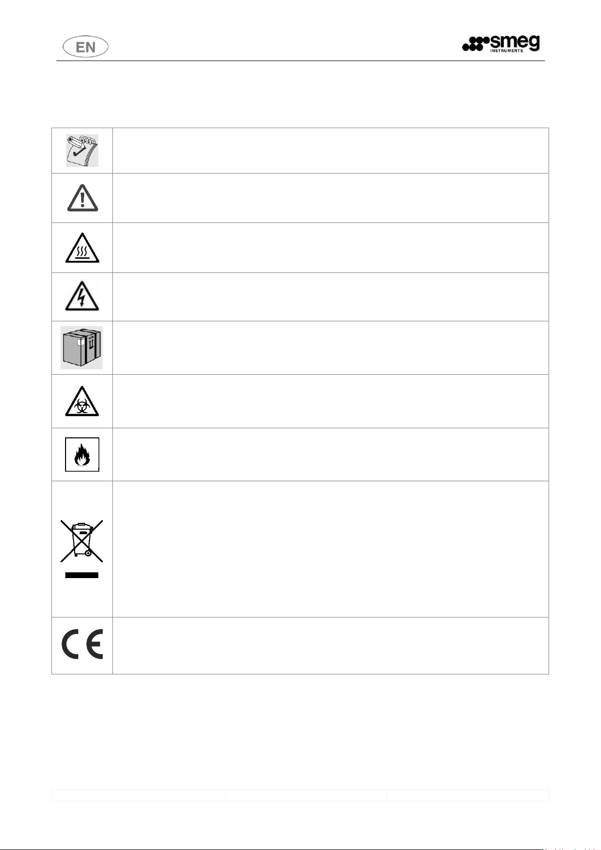
2 KEY TO THE SYMBOLS USED IN THE MANUAL AND ON THE APPLIANCE
The following is the key to the symbols used on the appliance and in this manual, as required by point 5.4.4.e of
IEC61010-2-040:2005.
Read with particular attention.
(Symbol which appears beside particularly important instructions or warnings).
Warning, danger: refer to the manual.
(The symbol appears on the appliance’s technical dataplate to emphasise that staff must read the
manual before using the device.
The symbol appears in the manual next to safety instructions)
Warning, hot surface.
(the symbol is affixed to the appliance close to parts which may heat to high temperatures and
constitute a burn hazard - do not touch parts near this symbol. The symbol appears in the manual to
emphasise safety instructions relating to the burn hazard).
Warning, electric shock hazard.
(The symbol is affixed close to live parts - the device’s power supply must be disconnected before doing
any work on these parts. Never touch live parts unless the electricity supply is disconnected).
Transport and unpacking precautions.
Biohazard.
Flammability hazard.
At the end of its working life, the product must be consigned to a disposal plant for recovery and
recycling in accordance with the relevant legislation in the country of installation. Contact the specialist
disposal consortia.
At the end of its lifetime the appliance may be contaminated, especially the chamber and water circuit
(e.g. if the appliance has ended its working life due to a fault that has caused the failure of the last
thermal disinfection cycle): take appropriate care when decommissioning.
THIS APPLIANCE IS MARKED ACCORDING TO THE EUROPEAN DIRECTIVE 2002/96/EC ON WASTE
ELECTRICAL AND ELECTRONIC EQUIPMENT (WEEE). BY ENSURING THIS PRODUCT IS DISPOSED OF
CORRECTLY, YOU WILL HELP PREVENT POTENTIAL NEGATIVE CONSEQUENCES FOR THE
ENVIRONMENT AND HUMAN HEALTH, WHICH COULD OTHERWISE BE CAUSED BY INAPPROPRIATE
WASTE HANDLING OF THIS PRODUCT.
CE marking: the manufacturer guarantees compliance whit the UE directives applicable to the product.
This symbol appears on the machine’s technical data label and in this manual.
GW6090
USER MANUAL
6
3 INTENDED USE
Professional glassware washing machines, laboratory glassware washers (GW – glassware washer).
The appliance is built to provide the following function:
Washing of laboratory glassware with chemical or thermal disinfection;
The appliance cannot be used to sterilize instruments or any other device.
The appliance cannot be used to sterilize instruments or any other device.
The type of instrument which can be processed in a cycle depends on the washing trolley used.
The device is supplied as standard without washing trolleys; contact the manufacturer for advice about the trolleys
best suited to your needs.
Any use other than that described in this manual constitutes misuse.
The manufacturer declines all liability for uses other than those stated above.
The manufacturer declines all liability for any damage caused by the use of the appliance to wash
glassware or instruments not approved by their manufacturers for automatic decontamination by means of
thermal disinfection.
The appliance may only be used by specifically trained staff. The authorized installation engineer will
train the staff assigned to use the appliance at the time of installation.
The manufacturer declines all liability in the event of malfunctions or accidents caused by use of the
appliance by untrained staff.
The training of the staff responsible includes specific information on the possible risks involved in the use
of the appliance, and training in the safest possible way of carrying out the operating procedures.
The installation engineer is also responsible for notifying the responsible authority of the USER and
SUPERUSER passwords for access to the setup parameters. The responsible authority must keep these
passwords in a safe place.
It is the duty of the appliance’s RESPONSIBLE AUTHORITY to ensure that those using the equipment have
been suitably trained in its operation, its safe use and routine checks, and that this training is suitably
maintained.
Staff training should be checked regularly.
The installation engineer is responsible for ensuring that it operates correctly after commissioning.
Safety information supplied in compliance with 5.4.101.1 IEC61010-2-040:2005
Instrument manufacturers’ instructions should always be followed when choosing the most appropriate
disinfection treatment.
In particular, it is important to check the compatibility of the load for treatment with the specific washing
cycle chosen, in terms of the maximum temperatures reached and the chemicals used.
Information supplied in compliance with point 5.4.4.r IEC61010-2-040:2005.
3.1 DEFINTITION: “RESPONSIBLE AUTHORITY” IN RELATION TO THE DEVICE
Responsible authority: “Person or group responsible for the use and ordinary maintenance of the unit and for operator
training.” Definition taken from point 3.5.13 of the IEC61010-1:2001 standard.
The responsible authority should be clearly identified within the facility where the appliance is used, (for example by
recording the relative names and responsibilities on corporate forms).
GW6090
USER MANUAL
7
4 GW – MODELS
Standard configuration of the product
Models features
GW6090B
GW6090BDS
P1 – peristaltic detergent pump
P2 – Neutralising agent peristaltic pump
P3 – optional peristaltic pump
P4 – optional peristaltic pump
P5 – optional peristaltic pump
Drying system
-
HEPA Absolute filter (dryer air)
-
Steam condenser
-
-
P1 Detergent dispensing monitoring
P2 Neutralising agent dispensing monitoring
P3 pump dispensing monitoring
P4 pump dispensing monitoring
P5 pump dispensing monitoring
Tank level sensor
P1 - SL1
Tank level sensor
P2 – SL2
Tank level sensor
P3 – SL3
Tank level sensor
P4 – SL4
Tank level sensor
P5 – SL5
Cabinet - housing detergent tanks
SYMBOL
MEANING
feature present
optional accessory, installable on the model in question
-
feature not present and not installable on the model in question.
Please contact your trusted dealer for more information and clarifications.
GW6090
USER MANUAL
8
5 GENERAL WARNINGS
.Leaning or sitting on the open door of the device might cause it to tip over, putting people in danger.
The door is not designed primarily to support loads.
.The maximum weight which can be loaded on the door, including the weight of the instrument trolley,
must never exceed 42kg.
.For optimal DRYING, the load for processing must never exceed 30 kg.
.With use of the device, localised or general discolouring of the heating element may occur. This is normal
since it is due to the operating mode and does not reduce the appliance’s effectiveness.
.In the event of malfunction, disconnect the appliance from the electricity supply and turn off the water
tap. Then contact your nearest authorised Service Centre.
.Open the door carefully, first waiting for the wash cycle to end. The appliance has an automatic door
opening system; do not force the door open while a program is in progress.
.The appliance must only be used by staff suitably trained in its operation.
.The chamber of the appliance is not designed for users to climb into it. The user must never climb into the
chamber; this might put his safety at risk (ref. 7.102 IEC61010-2-040:2005).
DEMI WATER ABSENCE
If demineralised water is not available, the user is responsible for ensuring that the quality of the water
supplied to the medical device does not cause mineral salts or other substances to be deposited on the
treated instruments, rendering their subsequent use unsafe.
Do not place flammable substances inside the device. Do not use flammable detergents.
Never place alcohol or solvents such as turpentine, which might cause an explosion, inside the appliance.
Do not place materials dirty with ash, wax or paint inside the appliance.
Never touch the heating element immediately after the end of a wash programme.
Do not touch any residual liquids left inside the washing chamber; scalding hazard (ref. 7.102.c IEC610102-040:2005).
When moving the appliance around, a forklift truck or pallet truck must be used.
Before leaving the factory, the base of the appliance is secured to a pallet, which is used for lifting and
transporting it.
Do not use appliances which have been damaged in transit!
If in doubt, contact your dealer.
Once decommissioned, the appliance must be rendered unusable. Cut the power supply cable after
removing the plug / disconnecting the cable from the power socket.
GW6090
USER MANUAL
9
5.1 ACCESSING AND REUSING THE DEVICE AFTER AN INCOMPLETE CYCLE
The instructions relating to the device’s safety in the event of an incomplete operating cycle are provided in
compliance with points 5.4.4.g and 13.1.102 of IEC61010-2-040:2005.
WARNING
If a disinfection cycle is interrupted (by the user or due to an alarm generated by the appliance itself): take
care when handling the instruments and the load in general in the washing chamber. The load and the
internal parts of the appliance might be biologically contaminated/infected.
Before handling tools or performing any maintenance: Perform a complete disinfection cycle or, if you
cannot perform a complete Thermo-disinfection cycle, handle tools with caution (using protection devices
required for the handling of infected instruments, eg. gloves, lab coat).
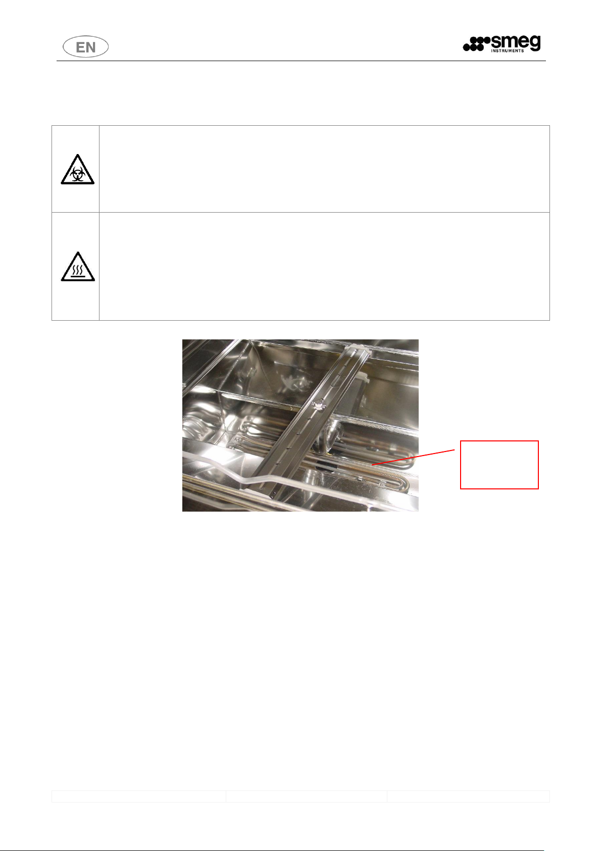
DANGER, HOT SURFACES
The appliance performs a thermal disinfection cycle using water at high temperatures (up to 93°C) and
detergents. If, in the event of a failure, there is water in the chamber when the door is open: avoid contact
with the skin, burning hazard and risk of irritation due to the toxicity of the chemicals used.
Never touch the heating elements inside the chamber.
Contact Smeg authorised technical staff in the event of a failure.
Fig. 1- View of inside of chamber, detail of heating elements.
Do not touch
the heating
elements
GW6090
USER MANUAL
10
6 GENERAL OPERATING INSTRUCTIONS
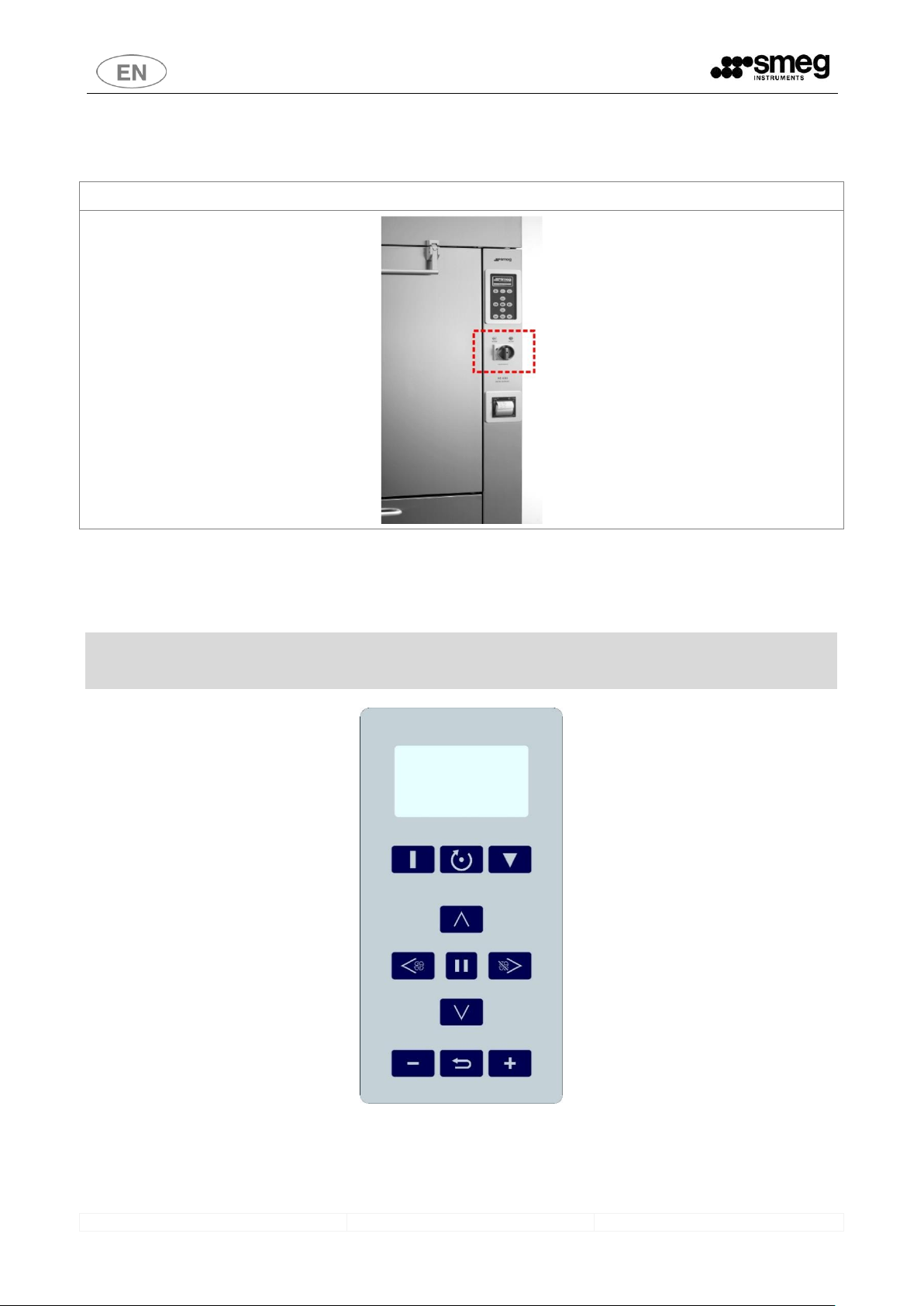
6.1 POWERING
Switch that powers on the machine is the red element on the front of the machine, under the control panel.
6.2 CONTROLS
The keyboard is divided into two separate sections:
. The upper part, with keys for starting and stopping a program, and for the reset process;
. The lower part, which contains the keys used for selecting/editing programs, selecting the machine parameters and
the various functions/adjustments.
A complete list of the keys and their relative functions is given below.

GW6090
USER MANUAL
11
KEY
FUNCTION
KEY
FUNCTION
1 - START, starts the selected program
6 - LEFT – DRYER ON, key used to select the
separate drying cycle (if available); it is also
used for moving to the left in each menu.
2 - RESET, forces the machine to run through a
reset procedure (both in the case of a deadlock
and in other situations, such as those after an
alarm has occurred)
7 - RIGHT – DRYER OFF, selection key for
deactivating the drying cycle (if available); it is
also used for moving to the right in each menu.
3 - STOP, stops the current program (also for
the printing of the last cycle).
8 - ENTER, confirms the selection made /
program selection / door opening.
4 - UP, selection key (scroll up).
9 - INC, increases the value / selects “yes”/
setting of the delayed start (max 24h)
5 - DOWN, selection key (scroll down),
(also for the printing of the machine
parameters).
10 - ESC, quits the current mask and goes back
to the previous step.
11 - DEC, decreases the value in question /
selects “no”
Symbols similar to the keys appear on the bottom line of the display as their functions are activated.
Some keys have special functions depending on the active screen, such as the "STOP" key: if used when the machine is
stopped, has the function to “send to the printer” the last cycle performed.
In case of “no energy supply”: the door is locked.
Do not try to force the opening, in order to avoid damages to the security lock.
7 FUNCTIONING
Basic steps for using the device, once installed, are:
1. Correct positioning of the load to be processed within the washing trolleys in the chamber.
2. Installation and connection of detergents tanks.
In the following, the instructions to access the washing chamber of the device and for the opening of the cabinet side.
7.1 HOW TO OPEN THE WASHING CHAMBER DOOR
The device is provided with an automatic locking system.
Do not force the opening of the door, proceed as described:
Connect the machine to the electricity supply.
Power on the machine turning the main switch on.
Wait for the device initialization, then press the “ENTER” key for the opening of the door.
After pushing it, to open the machine the door handle should be lifted.

GW6090
USER MANUAL
12
The door may be opened during the cycle only if the temperature inside the washing chamber has not
exceeded 40°C. Use the keyboard to open the door.
Depending on the settings chosen for the system, a password must be entered to open the door.
It is always advisable to wait until the cycle terminates before opening the door.
7.2 DETERGENT COMPARTMENT OPENING
Detergent compartment (the steel door of the bottom compartment): simply pull the door to open it.
fig. 2 – Detergent compartment door opening.
7.3 HOW TO CONDUCT A WASHING/DISINFECTING CYCLE
Once the device has been installed, the detergent cans have been connected and the trolleys have been loaded, to
perform a washing cycle:
Power up the device by turning the MASTER SWITCH from “0” to “I”;
Wait for a moment to allow the system to load: the screen of the last program selected will appear (e.g.
“PLASTIC 70°C”);
Press ESC to access the program selection menu;
Use the UP and DOWN keys to choose the program required.
Press ENTER to confirm the program.
Press START to start the selected program.

GW6090
USER MANUAL
13
< 1 PREWASH >
< 2 DEMI PREWASH >
< 3 PLASTIC 70°C >
< 4 SHORT 60°C >
. . .
Fig. 3 - Program selection screen
PR: PLASTIC 70°C + Dry
(000003)
Phases N.: 5
Duration: 1:10:00
< Drying On >
05/02/2013 08:30:15
Fig. 4 - Screen of the program selected
Once the program has started, the display shows the following information:
the name of the program being run (e.g. “PLAST 70°C”);
the current phase and the process being carried out (e.g. “PRELOADING”);
TL - the temperature inside the washing chamber;
TC - the control temperature;
RunT - the time since the program started.
The end of the cycle is shown on the display by a specific screen: the cycle has been completed successfully. At the end of the cycle
the user can open the door by pressing ENTER.
Once the door is open, the processed instruments can be unloaded. The device is ready to perform a new washing/disinfection
program.
It is best to wait a few minutes between cycles, with the door of the device open, to allow the washing chamber to
cool, making the next washing cycle more effective.
A low temperature at the start of the washing cycle provides full benefits from the combined action of time and
temperature during the process and the detergent used.
PR: PLASTIC 70°C + Dry
F0 PREWASH
PRELOADING
TL 19.5 TC 19.8
RunT 0:00:20
Fig. 5 - screen of the programming which is running
PR: PLASTIC 70°C + Dry
PROGRAM ENDED
OPEN THE DOOR?
Fig. 6 - “Program ended” screen.
7.4 HALTING A PROGRAM IN PROGRESS
To interrupt a program in progress: press STOP.
Once the button is pressed, the program switches to pause state:
The door can only be opened until the temperature is less than 40°C, by pressing ENTER
Restart the cycle within 60 seconds by pressing START.
7.5 PERFORMING A STAND-ALONE DRYING CYCLE
The drying phase is set for every program (except for prewash programs) by default.
To start a “stand-alone” drying phase:
Press “LEFT” from the menu of the selected program.
The drying phase activation screen appears: press ENTER to confirm the start of drying (or press ESC if you prefer to go
back to the previous screen).
Parameters on the display during drying:
o Phase name
o TA1: Drying System temperature probe;

GW6090
USER MANUAL
14
o TT: phase target temperature;
o RunT: time passed.
DRYING
Confirm?
Fig. 7 - drying cycle selection screen: Confirm with ENTER.
PR: DRYING
DRYING
TA1 74.5
TT 80.0 RunT 0:00:55
Fig. 8 - screen: drying cycle in progress.
At the end of the phase, open the door and wait a few minutes before extracting the instruments, to allow both the well and the
processed material to cool down (the drying phase concludes with a cooling phase).

GW6090
USER MANUAL
15
7.6 PRINTING OUT THE LAST CYCLE PERFORMED
N.B.: the printer is an optional and not part of the standard equipment.
The last cycle performed can be printed out with the device in standby mode. Proceed as follows:
Press STOP with the screen of the last cycle performed on the display.
The print confirmation prompt screen appears: press ENTER to confirm or ESC to abort.
PR: PLASTIC 70°C + Dry
(000003)
Phases N.: 5
Duration: 1:10:00
<Drying On>
05/02/2013 08:30:15
Fig. 9 - screen of the last program performed
PRINT LAST CYCLE?
< YES >
Fig. 10 - printout confirmation screen.
7.7 POSTPONING THE CYCLE START
Maximum delay setting: 10 hours. To postpone the start of a cycle:
press INC with the screen of the cycle selected on the display.
The delay time setting screen appears;
Set the delay time using the R and L selector buttons to locate the cursor on the hours and minutes and the INC and DEC
buttons to increase or decrease the value.
PR: 3 PLASTIC 70°C + As
(000003)
Phases N.: 5
Duration: 1:10:00
<Drying On>
05/02/2013 08:30:15
Fig. 11 - screen of the last program performed
PR: postponed
3 PLASTIC 70°C
Type delay
Hours 00 Min 00
05/02/2013 08:30:15
Fig. 12 - postponed start setting screen.
7.8 SECURITY POLICY, USER AND SUPER USER PASSWORDS
For safety reasons, the device implements a protection policy with four password levels that enable or deny access to
the menus of the appliance.
user level: concerns the people who actually operate the machine (nurses, assistants, department heads). This
password enables access to the “program selection” and “change password” menus only.
super user level: concerns the person in charge of the machine (department head, clinical engineer, etc.). This
password can be used to access the following menus:
o PROGRAMMING: Loading Programs;

GW6090
USER MANUAL
16
PROGRAM EDITING -> only in relation to the amount of detergent and the drying parameters;
COPY
NEW PROGRAM
o UTILITY: accesses all the sub-menus (can also change the user passwords)
o WASHING PARAMETERS: only certain sub-menus, as listed below:
WATER CONNECTION
WATER TRAP WASH
REGENERATION
DRAINING
Technical level: concerns authorized technicians.
All the menus in the lower levels as well as other “WASHING PARAMETERS” submenus can be accessed from this level,
i.e.:
EXTRA FILLING TIME
DRAINED WATER RECOVERY
CONDENSER ACTIVATION
DETERGENT DISPENSERS
FLOWMETER
CONDUCTIVITY SENSOR
DWP ACTIVATION
TEMPERATURE ADJUSTMENT
MAINTENANCE
Manufacturer level: concerns the manufacturer of the appliance.
Default Passwords:
USER
PASSWORD
USER
PASSWORD
User 1
1
User 11
B
User 2
2
User 12
C
User 3
3
User 13
D
User 4
4
User 14
E
User 5
5
User 15
F
User 6
6
User 16
G
User 7
7
User 17
H
User 8
8
User 18
I
User 9
9
User 19
J
User 10
A
User 20
K
SuperUser (Tech
user)
The password will be given
by authorized technician
Remember to change the password when the appliance is used for the first time so as to be certain of who
is enabled to access the machine.
The “User Control Activation” option can be activated to make sure that the appliance is operated by
authorized users.

GW6090
USER MANUAL
17
8 COMMISSIONING INSTRUCTIONS
Once the appliance has been installed correctly, it must be prepared for use:
Connect detergent and neutralising agent tanks and any other chemicals.
Open the water supply taps.
8.1 EXTERNAL WATER SOFTENER
The machine is not equipped with a water softener.
We suggest the installation of a water softener in order to supply the necessary water for on working day and to
enable the water softener to regenerate during the night.
Characteristics of the suggested water softener:
Minimum capacity 10 l/min (600 l/h)
Supply pressure min 2 – max 5 bar
Hardness of out coming water < 8°F
Cycle capacity of the system about 1.800 litres
Please contact your local dealer for suggestions about water softeners.
The basic range of water softeners is available on the manufacturer website.
8.2 USING DETERGENTS
One fundamental factor for a good washing process is the type of detergents used.
The manufacturer guarantees excellent washing results with the use of the recommended products.
The device is equipped with automatic detergent dispensing devices.
DISPENSING DEVICE
USE OF DEVICE AS GLASSWARE WASHER
P1
neutral or weak alkaline liquid detergent
P2
acid neutralising agent
P3
NaOH 33%
P4
Antifoam
P5
Optional agent
Key: feature installed, optional feature, - feature not available for installation
ATTENTION
If the can level sensors are not fitted: check the levels of product in the cans / bottles to ensure that programs are not
performed without detergent or neutralising agent.
Always comply with the INSTRUCTIONS provided by detergent PRODUCERS, especially with regard to the
RECOMMENDED DOSES, the correct TEMPERATURES for their use and STORAGE instructions. Safety information about
doses supplied in compliance with 5.4.4.s of IEC61010-2-040. Refer to the product instructions and technical safety data
sheets.
8.2.1 LIQUID DETERGENT INTAKE SYSTEM
Each peristaltic pump is supplied with a detergent intake system, in two possible versions.
a. STANDARD version (Intake system installed by default on the GW range):
1. one stainless steel intake pipe, to suck in detergent from the can;
2. a support, a conical rubber-fitting support, to position the intake pipe correctly;
Standard Configuration, with LEVEL SENSOR. Intake nozzle with integral:
Level sensor and support for fitting onto the can.
High-strength rubber hose for connection between intake pipe and peristaltic pump.
Detergent intake filter, fitted directly on the suction nozzle pipe.

GW6090
USER MANUAL
18
WARNING
The label on the intake pipe must correspond to the type of detergent being used. Refer to the following
colour code:
P1 - White/clear: alkaline detergent; P2 - Red: acid neutralising agent
P3 - Blue: additive; P4 - Green.
Connection errors reduce the effectiveness of the process and may damage parts of the circuit. Detergent
intake system connection errors lead to the loss of Warranty cover for the parts concerned.
The intake pipe is supplied complete with intake filter. Make sure that the filter is always fitted and correctly
positioned to keep the detergent dispensing system in good working order. Check the rubber connection
hose regularly for leaks.
fig.13 - Fitting the detergent intake nozzle into the can. Fit the cap over the top of the can for a perfect, secure connection. The
intake nozzle is supplied complete with intake filter. (the illustrations show various versions available).
8.2.2 GENERAL PRECAUTIONS FOR DETERGENTS
HANDLE DETERGENT CANS WITH CARE
Detergents may be TOXIC. Refer to the product safety data sheets.
Once a product has run out, replace the empty can with a full can of the same product.
If the product left in the old can is poured into the new one, take care not to overfill the new cans to ensure
that they will not overflow when the suction nozzles are inserted. Gloves must be worn during any handling
of detergents. Information supplied in compliance with 5.4.3.m, 5.4.4.n and 5.4.4.q IEC61010-2-040:2005
DETERGENT SAFETY DATA SHEETS.
Detergent SAFETY DATA SHEETS must be kept: close to the place where detergents are stored, close to the
appliance, in an easily accessible location. The latest versions of the safety data sheets should be requested
regularly (e.g. once a year). Safety data sheets will be supplied by the producer on request. Refer to safety
data sheets for first aid procedures in the event of accidental contact with detergents.
DISPOSAL
Information supplied in compliance with point 5.4.4.L of IEC61010-2-040:2005.
DISPOSAL of any product residues and containers (cans and bottles): refer to the “DISPOSAL ADVICE” section
of product safety data sheets. The appliance’s responsible authority must dispose of detergent residues and
containers in accordance with the relevant national or local legislation.
.

GW6090
USER MANUAL
19
9 LOAD PREPARATION - GW
Loading instructions are provided in compliance with 5.4.4-k of IEC61010-2-040:2005.
The load for processing must be arranged appropriately on the most suitable supports for machine-washing.
Effective washing starts with preparation of the elements / glassware for processing.
Therefore, before placing the glassware and the other items of the load in the specific baskets, it is
necessary to remove any large residues deriving from previous use, by soaking, treatment or
rinsing.
Stainless steel items cannot be immersed in physiological solutions of sodium chloride, as prolonged contact causes
corrosion and damage to the surface due to stress corrosion cracking.
Do not overload the washing baskets to ensure effective mechanical action of the water across the entire surface of
the glassware.
To allow effective cleaning and prevent damage to the objects for processing, glassware must be properly arranged on
the most suitable supports for machine-washing.
Contact your local dealer for advice about the washing trolleys best suited to your needs.
Items which can be dismantled must be prepared and stowed as instructed by the manufacturer.
For effective cleaning, items with hinged joints must be opened to minimise the overlapped surfaces. The instrument
holder devices used and the fixing devices must be designed so that no shadow zones are created during subsequent
cleaning and disinfection.
Make sure that there are no labels on the glassware for washing which may detach during the process.
GLASSWARE WASHING SUPPORTS - TROLLEYS
The appliance comes without washing trolleys.
Refer to the washing trolley manuals for guidance on their correct use.
Avoid direct, repeated contact with dirty material.
Always take the greatest care and use suitable personal protection equipment, both before and after
treatment.
Before processing glassware or any other object in the glassware washer, check on the
manufacturer’s instructions that the items are approved for automatic treatment in the Glassware
Washer and also the recommended maximum washing temperature.

GW6090
USER MANUAL
20
10 WASHING PROGRAMS - DESCRIPTION
The default ‘original’ programs are installed in program positions 1 to 20. These programs have been researched and
formulated so as to guarantee the best possible washing and disinfecting results. However, they can be changed in
relation to the quantity of detergent.
The remaining 10 positions from 21 to 30 are empty and can be used by the customer to create his own programs.
These new programs can either be created in the manual mode by means of the keyboard, or by using the
“WDTRACE” software (which can be purchased as an optional).
It is always possible to reinstall the original programs by loading them (consult the relative section).
10.1 PARAMETRO DI TERMODISINFEZIONE A0
The A0 parameter (introduced by the EN ISO 15883 standard1) allows a numerical value to be assigned to the thermal
disinfection carried out.
When calculating the parameter, only the time intervals during which the temperature is above 65°C are considered.
For our thermal disinfection programs, the calculation is simplified by only including the “extension” phase, when the
temperature is kept constant at close to the target value set.
Programs that include thermal disinfection have therefore been designed to offer the following A0 values:
Temperature [°C] and time [min]
A0
90°C - 1’
600
90°C - 5’
3000
93°C - 5’
6000
93°C - 10’
12000
The formula for calculating A0 is given below.
10
80
0
10
T
A
= Time in seconds for which the disinfection temperature must be maintained.
T
= Disinfection temperature in °C.
If the temperature is 80°C, A0 is equal to the temperature maintenance time in seconds.
1
EUROPEAN STANDARD EN 15883 “Washer-Disinfectors” , with particular reference to section 3 Terms and Definitions
and annex B, A0 concept. of part 1 of the standard, 15883-1.

GW6090
USER MANUAL
21
11 ABBREVIATIONS LEGEND
Abbreviations used to identify the components
BPE: Door-lock system
EVC: hot (warm) water inlet valve.
EVD: Demineralized water inlet valve.
EVF: Cold water inlet valve.
FM1, FM2… , FM5: peristaltic pumps P1, P2… P5 flowmeters
FMC: warm water flowmeter
FMD: demineralized water flowmeter
FMF: Cold water flowmeter
K: heating elements relay
MA: drying system motor.
MCM: Door position (signal switch)
MCP: Door position (signal switch)
ML1, ML2: washing pump
MS: draining pump
P1, P2, …, P5: detergents peristaltic pumps
PAP: high pressure switch (washing pump ML monitoring)
PL1: working level pressure switch
PS: safety level pressure switch.
R1, R2, R3: chamber heating elements.
RA1, RA2: Drying System heating elements.
EMF (SF): Mains EMI filter (electrical).
SP1, SP2, … , SP5 (also SL1, SL2,… SL5): Detergent tanks level sensors.
TA1, TA2: PT1000 probe, Drying temperature sensor
TCL: PT1000 probe, washing chamber temperature control sensor
TL1: PT1000 probe, washing chamber temperature working sensor
THS1: Drying system elements safety thermostat.
THS: Chamber heating elements safety thermostat.

GW6090
USER MANUAL
22
12 ALARMS MESSAGES
There are two different situations, depending on how serious the fault is:
warning messages; there will be a message allowing the user to ignore the warning and proceed with the
selected cycle.
true alarm signals. The user must press the “RESET” button and comply with the relative procedure in order
to overcome the situation.
By and large, an alarm indicates that the machine is operating in a faulty way and needs to be repaired by a
technician. Sometimes, however, the alarm may be caused by a temporary situation. Before calling the authorized
Technical Assistance service, you are therefore advised to make a RESET and repeat the cycle a second time. Call the
authorized Technician if the alarm persists.
When an alarm message is noticed: Refer to the table below to find out what the code means and the relevant
countermeasures. Apply the countermeasures recommended for the specific circumstances.
DEFAULT PROCEDURE for all the alarms:
1. Perform the RESET cycle.
2. If the alarm message disappears after the RESET cycle: normal use of the device can be
restarted.
3. If the alarm message persists after the RESET cycle: switch the device off and back on using the
“On/Off” main switch (Wait at least 10 seconds after switching off before switching back on
again).
4. If the alarm occurs when the device is restarted: retry the RESET.
If a cycle has been stopped during a high temperature phase, remember that the temperature must drop
below 45°C before the door can be opened.
If the alarm persists even after the RESET procedure:
1. Turn off the water supply taps.
2. Disconnect the appliance from the electricity supply.
3. Check that all the device’s connections (electricity and water) are correct and there have been no changes
from the initial installation conditions.
4. Contact the After-Sales Service.
In case of water leakage: immediately Turn off the water supply taps and contact the After-Sales service.
Maintenance and any repairs must be carried out by authorized technical staff.
For your own safety and for the safety of the device, the user activities are limited to control activities,
external to the device, and to the activation of the RESET cycle, if requested.
ALARM ID
DISPLAY MESSAGE
MEANING AND SUGGESTED USER ACTION
ID1
“Water heating failed”
Water not heated within time allowed.
.Check the condition of the safety thermostat.
.follow the DEFAULT PROCEDURE described above.
ID2
“Temp. Probe TL1-TC”
The temperature difference between the two probes, “TL1” and
“TC”, is more than 2°C
.follow the DEFAULT PROCEDURE described above.
ID4
“Overtemperature TL1”
Probe “TL1” (chamber temperature) reads a higher temperature
than the target one.
.follow the DEFAULT PROCEDURE described above.

GW6090
USER MANUAL
23
ALARM ID
DISPLAY MESSAGE
MEANING AND SUGGESTED USER ACTION
ID5
“Probe TL1 disconnected”
Working temperature probe “TL1” is generating an abnormal
signal (probe “open”).
.follow the DEFAULT PROCEDURE described above.
ID7
“Probe TA1 disconnected”
Drying temperature probe TA1 is generating an abnormal signal
(probe “open”).
.follow the DEFAULT PROCEDURE described above.
ID8
“Probe TA2 disconnected”
Drying temperature probe TA2 is generating an abnormal signal
(probe “open”).
.follow the DEFAULT PROCEDURE described above.
ID9
“Probe TB disconnected”
Boiler temperature probe TB is generating an abnormal signal
(probe “open”).
.follow the DEFAULT PROCEDURE described above.
ID10
“Probe TCL disconnected”
Control temperature probe TLC is generating an abnormal signal
(probe “open”).
.follow the DEFAULT PROCEDURE described above.
ID11
“Lack of cold water”
No cold water during filling phases.
.Check the water supply.
.Check that the intake tap is open.
.Check the water supply pressure.
.Check that the filler hoses are correctly positioned.
ID12
“Lack of warm water”
The same as ID11 for the warm water.
.Check the correct setting of the parameters of the device
(effective presence/absence of warm water).
ID13
“Lack of demi water”
The same as ID11 for the demi water.
.Check the correct setting of the parameters of the device
(effective presence/absence of demi water).
ID17
“Cold water load time exceeded”
Cold water filling time not correct.
.The same checks as for ID11
ID18
“Warm water load time
exceeded”
Warm water filling time not correct.
.The same checks as for ID12
ID19
“Demi water load time
exceeded”
Demineralized water filling time not correct.
.The same checks as for ID13
ID20
“Water load system failure”
.The same checks as for ID11, 12, 13
ID22
“Cold water flowmeter failure”
.The same checks as for ID11
ID25
“No Press in Hyd Sys Foam(?)”
Anomaly related to the circulating pump “ML”. Circulating
pump pressure too low. There may be foam in the chamber.
.Check the type of detergent used.

GW6090
USER MANUAL
24
ALARM ID
DISPLAY MESSAGE
MEANING AND SUGGESTED USER ACTION
ID29
“Washing chamber drainage
failed”
Chamber does not empty. No drainage.
.Check the connection to the water drain,
especially that the height of the drain connections complies
with the specified requirements and that there are no
restrictions in the drain hoses.
ID30
“Safety chamber level exceeded”
During the working cycle, the chamber water level exceeds the
safety level.
Check the water supply to the appliance:
1. Intake pressure.
2. That the connections are correctly set, as specified.
ID31
“Safety level
Safety level failed”
.The same checks as for ID30
ID32
“Sump full
Turn the taps off”
Water standing in washing chamber with appliance in standby.
.The same checks as for ID30
ID33
“Alarm 33”
Alarms active on previous product series – relating motorized
separation valves for drying system / washing circuit.
33 -> Separation valve not closing
34 -> Separation valve not opening
.follow the DEFAULT PROCEDURE
ID34
“Alarm 34”
ID37
“Not reached Target
Cooled Drainage”
Drainage problems when using a mixture of water. The use of a
mixture of water is an option adopted in special cases to cool
the water discharged into the drain.
Check:
1. The intake water temperature; if the water is not cold
enough (recommended T<25°C) there may be difficult in
achieving the target temperature.
2. Problems with drain; check that the hoses and drain
connections meet the specified requirements.
ID38
“Cooled Drainage failed”
.The same checks as for ID37
ID41
“Detergent 1 Inflow failed”
. Check the detergent presence.
. Check that the detergent intake nozzle is correctly positioned
in the tank.
. Check for detergent leaks (pools of detergent around the
device).
ID42,
ID43,
ID44,
ID45
“Detergent 2, 3, 4, or 5
Inflow failed”
.The same checks as ID41, for the detergents 2, 3, 4, 5.
ID46
“Pump tube 1 clogged”
.The same checks as for ID41
ID47,
ID48,
ID49,
ID50
“Pump 2, 3, 4 or 5 tube
clogged”
.The same checks as ID41, for the detergents 2, 3, 4, 5.

GW6090
USER MANUAL
25
ALARM ID
DISPLAY MESSAGE
MEANING AND SUGGESTED USER ACTION
ID52
“Door 1 electrically open”
Door locking mechanism failure.
1. Make sure the door is closed properly before starting a
cycle.
2. Do not force the door open with a cycle in progress; always
use the buttons provided on the appliance to stop a cycle and
open the door.
3. Check there is nothing between the door and the appliance’s
chamber preventing the door from closing properly.
4. Follow the DEFAULT PROCEDURE described above.
ID54
“Door 1
mechanically open”
Door opening detected with cycle in progress. Door interlock
microswitch malfunction.
.The same checks as for ID52.
ID56
“Doorlock 1
failure”
.The same checks as for ID52.
ID58
“Drying 1 failure”
Drying heating system failure.
.follow the DEFAULT PROCEDURE described above.
.Check the condition of the safety thermostat.
ID59
“Drying 2 failure”
ID67
“Cooling failed
WARNING: high Temp”
Dryer motor “cooling” malfunction. “Cooling” phase is included
at the end of the drying phase to bring the load processed and
the heating elements to a safe temperature.
.follow the DEFAULT PROCEDURE described above.
ID68
“Tank 1 empty”
.Check that there is detergent in the jerry can P1 or that the
level sensor is operating correctly.
ID69,
ID70,
ID71,
ID72
“Tank 2, 3, 4 or 5 empty”
.Check that there is detergent in the jerry can or that the level
sensor is operating correctly.
ID73
“Archive error”
Internal memory data storage error.
.follow the DEFAULT PROCEDURE described above.
ID77
“Temperature > 45”
Intake water temperature over 45°C; prewash temperature
must be below 45°C.
.Wait for the appliance to cool before starting a new cycle.
.Check the cold water temperature
.Verify the correct setting of the water supply.
ID78
“Recovery failed”
Microprocessor error.
Call the Technical Assistance Service if the fault persists.
ID79
“Program not congruent”
This alarm is triggered if a program is created using the
WDTRACE software using settings not compatible for the
proper performance of the cycle.
.Reconsider the program created phase by phase
ID80
“Warm water
flowmeter failure”
Warm Water, intake control system failure.
.Check the water supply settings.

GW6090
USER MANUAL
26
ALARM ID
DISPLAY MESSAGE
MEANING AND SUGGESTED USER ACTION
ID81
“Demi water flowmeter failure”
Demi Water, intake control system failure.
.Check the water supply settings.
ID82
“System failure sol 1”
Door locking mechanism failure.
1. Make sure the door is closed properly before starting a
cycle.
2. Do not force the door open with a cycle in progress; always
use the buttons provided on the appliance to stop a cycle and
open the door.
3. Check there is nothing between the door and the appliance’s
chamber preventing the door from closing properly.
4. Follow the DEFAULT PROCEDURE described above.
Anomalia nella chiusura porta della vasca.
ID84
“Overtemperature TA1”
Dryer temperature reading higher than target temperature.
. Follow the DEFAULT PROCEDURE described above.
ID91
“Archive full”
Internal memory full.
.Memory space must be cleared to allow use of the appliance
to continue: this can be done by connecting to the appliance
by means of the RS-232 serial port and using the WDTRACE
software.
ID92
“Change filter”
The absolute filter in the drying system has exceeded the set
number of working hours. Contact the After-Sales Service to
have the filter changed. The filter is a consumable and is not
covered by the warranty.
ID93
“Service”
The appliance has exceeded the set number of operating hours
since installation or since its last service: contact the AfterSales Service for routine maintenance.
ID94
“Temperature floating”
Temperature below TARGET temperature during extension
phase.
. Follow the DEFAULT PROCEDURE described above.

GW6090
USER MANUAL
27
13 CLEANING AND MAINTENANCE
DISCONNECTING THE ELECTRICITY AND WATER SUPPLIES
Before doing any maintenance work: disconnect the power supply using the appropriate switch on the
panel or disconnecting the power cable, and turn off the water intake tap.
WORKING SPACE REQUIRED: A space of approx 1m2 is required in front of the appliance for cleaning and
maintenance to be carried out without difficulty.
POWER CABLE REPLACEMENT
If damaged power cables have to be replaced, type FROR 450/750 cables with the same gauge as the
cables mounted in the factory must be used (the cables fitted are marked with their types and
characteristics). This replacement may only be made by authorized technical staff. Use genuine spare parts.
WARNING
Any work done on the appliance by unauthorized staff is not covered by the warranty and is performed
under the user’s responsibility.
During maintenance and cleaning: if appropriate, use personal protection equipment.
13.1 CLEANING THE DEVICE AND ITS PARTS
General cleaning
The external surfaces and inner door of the device must be cleaned at regular intervals (once a month is
recommended) with a soft cloth soaked in water or a normal detergent for steel surfaces.
The door seals must be cleaned with a damp sponge.
After cleaning, a washing cycle should be carried out without a load for processing, to remove any detergent residues.
Cleaning the water intake filter
The water intake filter "A" on the outlet of the tap requires regular cleaning; the recommended interval is once every
2 – 6 months, depending on the intake water quality. Turn off the water supply tap, unscrew the end of the water
intake hose, remove the filter "A" and clean it gently under running water. Fit the filter "A" back in place and
reconnect the water intake hose with care.
Keep an eye on the free end of the hose to prevent water spills.
fig. 14 – water intake filter "A"
Cleaning the spray arms
The spray arms can easily be removed by unscrewing the knurled nut that fixes them to the pivot pin, so that the
nozzles can be periodically cleaned to prevent fouling.
Wash the spray arms under running water and then fit them back in place. Make sure that they are free to turn
unimpeded.
Recommended spray arm cleaning interval: once a week.
For trolleys with fixed spray nozzles: refer to the trolley manual for cleaning instructions.

GW6090
USER MANUAL
28
fig. 15 – Appliance spray arm: remove and clean regularly to maintain optimal washing results.
Cleaning the filter unit
To ensure that the appliance operates effectively, it is extremely important to keep the filters clean. They should
therefore be inspected frequently (e.g. if glassware with paper labels is washed, inspect after each cycle - in normal
conditions the filters should be cleaned once a week) to remove deposits which may adversely affect operation.
WARNING
Filters and spray arms may contain biologically contaminated material and must be handled with due care,
using protective equipment (e.g. gloves, protective glasses, lab coat).
The potentially contaminated material in the filters and any other components of the device must be
handled and disposed of appropriately.
fig. 16 – Draining filters in the chamber; and detailed view.
Recommendations for correct maintenance
The filters should be cleaned under running water using a stiff brush.
It is essential to clean the filters carefully in accordance with the instructions given above: the appliance washer
will be unable to operate correctly if the filters are fouled.
Fit the filters back in place with care before starting a washing program.

GW6090
USER MANUAL
29
13.2 DRYING AIR FILTER
The air filters of the drying system must be periodically checked and changed. It is installed in the upper part of the
device, accessible after removing the side panels of the top.
The mat filter installed possesses 98% DOP efficiency and should be replaced at least once a year.
This operation is simple to do and the user can carry it out on his own after ordering the spare filter.
Unscrew the screw that holds the filter in place in order to disassemble the filter holder and install the new filter.
The ABSOLUTE 99.99% DOP (HEPA) filter is installed under the 98% DOP filter.
The filter remains efficient until it fully clogs, something that occurs progressively, thus reducing the volume of drying
air. It is advisable to replace the first stage once a year and to visually check to see how much the second filter has
darkened at this time.
The appliance will warn when the absolute filter needs replacing.
A clogged filter contributes to the degradation of the drying performance.
13.3 IF THE DEVICE IS TO BE OUT OF USE
If the appliance is to be left unused for a long time, follow these recommendations.
The procedure is recommended for periods of 24 hours or more out of use.
Perform the PREWASH program with the appliance empty (without load in the washing chamber).
If contaminated materials are processed: run a program with a thermal disinfection Td phase with no load in
the appliance.
Disconnect the electricity supply.
Leave the door slightly open to prevent unpleasant odours from forming inside the washing chamber.
Turn off the water intake tap.
13.4 REUSING THE DEVICE AFTER A PERIOD OUT OF USE
If the appliance has been unused for a long time, before starting a cycle, follow these recommendations.
Inspect the filters at the ends of the water intake hoses and check that no sludge or rust has deposited in the
pipelines; if this has occurred, allow water to run from the water supply tap for a few minutes.

GW6090
USER MANUAL
30
Restore the electricity supply (if disconnected).
Reconnect the water supply hose and turn on the tap.
Run a program with a thermal disinfection phase with no load for processing.
A thermal disinfection cycle should be performed before using the device if it has been out of use for 24
hours or more.
13.5 TROUBLESHOOTING
Slight faults can sometimes be eliminated by the user with the aid of the following instructions.
1. If the programme fails to start, make sure that:
The appliance is connected to the electrical mains.
The appliance is receiving power.
The water tap is turned on.
The door of the appliance has been closed properly.
2. If water stagnates in the device, make sure that:
There are no tight bends in the drain hose.
The drain trap is not clogged.
The appliance filters are not clogged.
3. If the items in the load for washing in general are not cleaned properly, make sure that:
The right amount of detergent has been added.
The water quality complies with the prescriptions.
The instruments have been positioned correctly.
The program selected is suitable for the type and degree of dirt on the instruments.
All the filters are clean and correctly fitted.
The spray arm water outlet holes are not clogged.
Nothing is preventing the spray arms from turning.
4. If the items in the load fail to dry or are dull, make sure that:
Absolute filter condition: operating hours can be viewed as an appliance parameter (the default operating hours
are set for normal conditions of use; the drying filter’s working life will be reduced by dirtier than average
environments).
There is neutralising agent in the container.
The neutralising agent dispenser is set correctly.
The detergent used is of good quality and has not lost its characteristics (e.g. owing to incorrect storage, pack left
open, etc.).
5. If the elements processed are streaked, stained, etc. make sure that:
The amount of neutralising agent dispensed is not excessive.
6. If there are visible traces of rust in the chamber:
The chamber is made of corrosion-proof steel, so any rust marks are due to external factors (pieces of rust from
the water pipes, etc.). Specific products for removal of these stains are commercially available.
Make sure that the detergent doses are correct. Some detergents can be more corrosive than others.
If the faults persist after the instructions given above have been followed, contact your nearest authorized service
center.

GW6090
USER MANUAL
31
14 ROUTINE INSPECTIONS AND MAINTENANCE
14.1 DAILY
1. Check the detergent and neutralising agent levels in the cans and fill up if necessary.
2. Check spray arm rotation and inspect the water outlet holes visually to check that they are clean.
14.2 WEEKLY
1. Clean the sump filters, following the instructions provided.
2. Run program with a thermal disinfection phase, without instruments for processing in the appliance, for
precautionary cleaning/disinfection of the washing chamber.
14.3 EVERY SIX MONTHS
1. Inspect the water solenoid valve intake filters; if necessary, clean them by pouring hot water through them in
the opposite direction to the operating flow.
2. Inspect the intake and outlet hoses of the detergent and neutralising agent pumps.
14.4 EVERY YEAR
Contact your nearest authorised Service Centre to have the appliance completely checked over at the end of the
warranty period and annually for successive years, or, if this occurs before the end of the year, when the “Appliance
maintenance” warning appears.
Maintenance operations are not covered by the product Warranty, which does not include the
replacement of components which deteriorate due to normal wear and tear.
The operations which the authorised staff will carry out are:
1. Inspection and if necessary replacement of worn peristaltic pump components (especially the internal hose)
2. Inspection of the detergent intake pipes and replacement if necessary.
3. Inspection of the door gasket and replacement if necessary.
4. Inspection of the drying system filters (relative and absolute) and replacement if necessary.
5. Inspection and if necessary cleaning/replacement of the filters (water intake filters on the filler pipes, detergent
filters on the suction systems).
6. Checking of the detergent dosage settings.
7. Check of the calibration of the temperature probes (tank and drying if present) and possible correction or
replacement of the probes.
8. Performance of a complete operating cycle, including the drying phase, to check for any leaks or malfunctions.
WARNING
The manufacturer declines all responsibility in the event of appliance malfunctions, or injury or damage,
arising from the failure to comply with the above recommendations.
Before doing any maintenance work: disconnect the power supply using the appropriate switch on the
panel or disconnecting the power cable, and turn off the water intake tap.

GW6090
USER MANUAL
32
15 INSTALLED MACHINE SET-UP
Machine model : ________________________________________________________
Machine serial number : __________________________________________________
Accessories present on the machine (place a check next to the accessory present and write the quantity provided):
CONFIGURATION TABLE
PERISTALTIC PUMPS - N.
(optional “P36090B” e “P46090B”)
1 2 3 4 5
DETERGENT LEVEL SENSOR - N.
“WD-LS5090”
1 2 3 4 5
DETERGENT FLOWMETERS - N.
“WD-FLUX”
1 2 3 4 5
PANEL PRINTER
“WD-PRINT6”
ELECTRICAL CONNECTION
3/N/PE
3/PE
CONDUCTIVITY SENSOR “IC6000”
DEMI WATER PUMP “PAD2”
DATA COMMUNICATION BOARD
“WD-LANI”
DOUBLE DRAIN VALVE “WD-VDS”

GW6090
USER MANUAL
33
INFORMATION AND AFTER-SALES SERVICE
Our Sales Department staff will be able to provide you with information about prices and special offers.
Our After-Sales Department will be able to provide you with guidance about keeping your appliance functioning
correctly and put you in touch with your nearest authorized Service Centre.
INTERNATIONAL CUSTOMERS
PLEASE CONTACT YOUR LOCAL DISTRIBUTOR
Smeg S.p.A.
Instruments Division
Via Leonardo da Vinci, 4 – 42016 Guastalla (RE) Italy
Tel. +39 0522 8211 – Fax +39 0522 821 592
E-Mail: instruments@smeg.it - service.instruments@smeg.it
www.smeg-instruments.com
19 390 6173 00
30 / 03 / 2016
Rev.
Date
 Loading...