

Page 1
GW6010
GW7010
GW7015
GW6010 – GW7010 – GW7015
GW – GLASSWARE WASHER Laboratory sector
- USER MANUAL -
Translation of the original instructions issued in Italian
Page 2

USER MANUAL
GW6010 – GW7010 – GW7015
Page 2 - 138
Summary
1 INITIAL RECCOMENDATIONS ..................................................................................................................... 6
2 SERVICE LIFE .............................................................................................................................................. 6
3 INTENDED USE AND CLASSIFICATION ........................................................................................................ 7
3.1 INTENDED USE ................................................................................................................................... 7
3.2 DEFINITION: “RESPONSIBLE BODY” OF THE DEVICE .......................................................................... 8
3.3 TYPE OPERATOR AND “SUPERUSER” ................................................................................................. 8
4 PRESENTATION .......................................................................................................................................... 9
4.1 WD6010 and GW6010 - MACHINE WITH SWINGING DOOR ........................................................... 10
4.2 WD7010 - GW7010, WD7015 – GW7015 – MACHINE WITH SLIDING DOORS ................................ 13
5 CONFIGURATIONS AND OPTIONALS ........................................................................................................ 18
5.1 GW6010 ........................................................................................................................................... 19
5.2 GW7010 ........................................................................................................................................... 20
5.3 GW7015 ........................................................................................................................................... 21
6 SAFETY AND HANDLING PRECAUTIONS .................................................................................................. 22
6.1 KEY TO THE SYMBOLS USED IN THE MANUAL AND ON THE MACHINE .......................................... 22
6.2 GENERAL RECOMMENDATIONS ...................................................................................................... 24
6.3 RECOMMENDATIONS FOR TRANSPORT .......................................................................................... 26
6.4 ACCESSING AND REUSING THE DEVICE AFTER AN INCOMPLETE CYCLE ......................................... 28
6.5 USE OF MULTI-PURPOSE TROLLEY .................................................................................................. 28
6.6 DOOR OPENING ............................................................................................................................... 29
6.6.1 GW6010 ................................................................................................................................... 29
6.6.2 GW7010 – GW7015 ................................................................................................................. 31
6.7 MANUAL DOOR UNLOCK ................................................................................................................. 33
7 OPERATING PROCEDURES ....................................................................................................................... 34
7.1 Access to detergent compartment .................................................................................................. 34
7.1.1 WD6010 - GW6010 .................................................................................................................. 35
7.1.2 WD7010 - GW7010 – WD7015 – GW7015 .............................................................................. 36
7.2 USE OF DETERGENTS ....................................................................................................................... 36
7.2.1 LIQUID DETERGENT SUCTION SYSTEM .................................................................................... 37
8 DETERGENTS ............................................................................................................................................ 38
9 LOAD PREPARATION FOR WASH CYCLE AND DISINFECTION................................................................... 40
10 BASIC OPERATIONS .............................................................................................................................. 42
Page 3

USER MANUAL
GW6010 – GW7010 – GW7015
Page 3 - 138
10.1 HOME SCREEN – ID 1.0.0.0 .............................................................................................................. 42
10.1.1 DOOR CONTROL - MACHINES WITH HINGED DOORS ............................................................. 42
10.1.2 DOOR CONTROL - MACHINES WITH SLIDING DOORS ............................................................. 42
10.2 PROGRAMS COMPLETE MENU - ID.1.1.0.0 ..................................................................................... 44
10.3 FAVOURITE PROGRAMS MENU - ID.1.1.0.0 .................................................................................... 44
10.4 PROGRAM START - ID. 1.1.1.0 ......................................................................................................... 44
10.4.1 EXTERNAL PERIMETER BUTTONS AND DATA. ......................................................................... 45
10.4.2 “INTERNAL PERIMETER” SCREEN DATA ................................................................................... 46
10.4.3 SELECTED CYCLE OPTIONS – ID. 1.6.1.0 ................................................................................... 46
10.4.4 CYCLE START – “USER CHECK” FUNCTION ACTIVE .................................................................. 48
10.4.5 NOTES ...................................................................................................................................... 48
10.5 PROGRAM UNDER WAY - 1.1.1.3 .................................................................................................... 48
10.6 SUBPHASES IN PROGRESS ............................................................................................................... 51
10.6.1 PROGRAM IN PROGRESS “DISPLAY EASY”- 3.4.2.1 .................................................................. 51
10.7 COMPLETED PROGRAM - 1.1.1.4 ..................................................................................................... 52
11 SETUP OPERATION - 1.4.0.0 ................................................................................................................ 53
11.1 SET UP DATE AND TIME – ID.1.4.2.1 ............................................................................................... 55
11.1.1 ENTER PASSWORD – ID.1.5.0.4 ............................................................................................... 56
11.2 LANGUAGE SELECTION – ID. 1.4.2.2 ................................................................................................ 56
11.3 COUNTERS – ID. 1.4.6.1 ................................................................................................................... 57
11.4 ARCHIVE AND PRINTER - ID 1.4.6.2 ................................................................................................. 58
11.5 MACHINE PARAMETERS – ID. 1.4.2.0 .............................................................................................. 61
11.5.1 DETERGENT DOSAGE SETUP (“Chemicals dosing”) – ID. 1.4.2.3 ............................................. 62
11.5.2 PROGRAMS ACTIVATION (“Programs enable”) – ID. 1.4.6.0 - 1.4.6.4 ..................................... 63
11.5.3 PASSWORD – ID. 1.5.0.1 .......................................................................................................... 65
11.5.4 LAN PARAMETERS – ID. 1.4.8.0 – 1.4.8.2 ................................................................................ 66
11.5.5 FULL S/N, MAC, ID (device labels) – ID. 1.4.8.1 ....................................................................... 66
11.6 DIAGNOSTICS OPERATIONS – ID.1.4.3.0 ......................................................................................... 69
11.7 PROGRAMS EDITING – ID. 3.4.2.1 ................................................................................................... 71
11.7.1 Customizing the program name .............................................................................................. 74
11.7.2 Customizing the program icon ................................................................................................ 74
11.8 DISPLAY AND SOUNDS – ID. 3.4.2.1................................................................................................. 75
11.9 ABOUT – ID. 1.4.5.0 – 1.4.5.1 .......................................................................................................... 75
11.10 USER PASSWORD – ID. 1503 ........................................................................................................ 76
11.11 HEATING TYPE – ID. 1465 ............................................................................................................ 78
11.12 WATER CONDUCTIVITY – ID.1466 ............................................................................................... 79
11.12.1 Purpose of the accessory ..................................................................................................... 80
11.12.2 Operation of the machine with the probe active: conductivity check function ................. 80
Page 4

USER MANUAL
GW6010 – GW7010 – GW7015
Page 4 - 138
11.13 TROLLEY CHECK – ID.14A0 ........................................................................................................... 82
11.13.1 OPERATION WITH OPTIONAL ACTIVE – TROLLEY CHECK .................................................... 86
11.14 SPRAY ARMS CHECK - ID 14A0 ..................................................................................................... 88
11.14.1 SPRAY ARMS CHECK – CYCLE IN PROGRESS ........................................................................ 90
11.15 AUTOMATIC OPERATION - ID.146B ............................................................................................. 91
12 ALARMS and WARNINGS ..................................................................................................................... 92
12.1 WARNING – ID 1.1.1.2 ..................................................................................................................... 93
12.2 ALARMS – ID 1.1.1.6 ........................................................................................................................ 95
13 CLEANING AND MAINTENANCE ........................................................................................................ 105
13.1 PRELIMINARY WARNING ............................................................................................................... 105
13.2 CLEANING OF THE DEVICE and its parts ........................................................................................ 105
13.3 Cleaning of the Filter Unit.............................................................................................................. 109
13.4 IN CASE THE DEVICE REMAINS UNUSED ....................................................................................... 110
13.5 DEVICE RE-USE AFTER A PERIOD OF IDLENESS .............................................................................. 111
13.6 TIME SCHEDULE FOR ROUTINE MAINTENANCE AND CHECKS ...................................................... 112
13.6.1 DAILY ...................................................................................................................................... 112
13.6.2 WEEKLY .................................................................................................................................. 112
13.6.3 EVERY SIX MONTHS ............................................................................................................... 112
13.6.4 EVERY YEAR ............................................................................................................................ 112
13.7 ELIMINATION OF SMALL TROUBLE ................................................................................................ 113
14 INSTALLATION .................................................................................................................................... 114
14.1 PACKAGE REMOVAL and PREPARATION FOR MOVEMENT ........................................................... 114
14.2 POSITIONING AND LEVELING......................................................................................................... 116
14.2.1 “SINGLE DOOR” MACHINE ..................................................................................................... 118
14.2.2 “DOUBLE DOOR” MACHINE ................................................................................................... 119
14.3 ELECTRICAL WIRING REGULATIONS .............................................................................................. 121
14.4 ACCESS TO THE ELECTRICAL CABLE AND TO THE WATER CHARGING HOSES ............................... 122
14.4.1 ACCESS FROM TOP OF DEVICE .............................................................................................. 122
14.4.2 ACCESS FROM REAR .............................................................................................................. 124
14.5 WATER SYSTEM SETUP .................................................................................................................. 127
14.5.1 WATER LOAD ......................................................................................................................... 127
14.5.2 DEMINERALIZED WATER........................................................................................................ 128
14.6 WATER DRAIN ................................................................................................................................ 129
14.7 STEAM SYSTEM CONNECTION (OPTIONAL) ................................................................................... 132
14.8 CHAMBER VENT CONNECTION (AIR AND STEAM) ........................................................................ 133
15 TECHNICAL CHARACTERISTICS ........................................................................................................... 134
16 MANUFACTURER REFERENCES AND AFTER-SALES SERVICE ............................................................. 138
Page 5

USER MANUAL
GW6010 – GW7010 – GW7015
Page 5 - 138
19 390 6599 - EN
03
04/07/2019
New functions ( Trolley check, Spray arms check,
Automatic operation).
New alarms and warning messages.
-
02
13/12/2018
GW7015
01
14/02/2017
This manual refers to FW CPU main master version 6.5.0:
Some features may be absent in previous versions of the
firmware.
Cod.
Rev.
Date
Note
Page 6
USER MANUAL
GW6010 – GW7010 – GW7015
Page 6 - 138
1 INITIAL RECCOMENDATIONS
READ THE PRESENT INSTRUCTION MANUAL CAREFULLY:
This manual constitutes an integral part of the machine.
It must be kept intact and at hand for the entire life cycle of the machine.
It is necessary to read the following manual carefully prior to using the device.
Failure to read or thoroughly comprehend the instructions in this manual may cause the device to malfunction and
present hazards to the user.
Machine installation, maintenance, and repair operations must be performed by authorized
technical staff.
Repair operations performed by unauthorized staff, besides leading invalidating the product
warranty, can be source of danger for the user.
In case of replacement, an original spare part must be used.
If the device was not used in accordance to the instructions presented in this manual, the
product may no longer be covered by warranty and the safety of this device could be
compromised (ref. par 5.4.4 IEC 61010-1:2010).
The producer declines all liability for any use that differs from what indicated in the present
manual.
Excluding possible manufacturing defects, consumable materials (Detergents, Air Filters,
Thermal Printer Paper…) are not covered under warranty.
The product warranty does not cover faulty parts due to negligence, inappropriate use, or
failure to comply with the instructions of the device operations; incorrect installation or
maintenance; repair and maintenance operations performed by unauthorized staff or with
non-original spare parts; transportation damages; and any circumstance that cannot be
ascribed to the device manufacturing defects.
Moreover, the warranty does not cover operations related to installation and connection of
alimentation and drain systems as well as maintenance operations provided in the instruction
booklet.
The installation of any accessory on the machine must be performed by authorized technical
staff.
To request further information about accessories: contact your trusted seller and/or the
authorized technical assistance, using the contact details provided in this manual (ref. 5.4.4.c
IEC61010-2-040:2015)
The content of this manual is for information purposes only. The content and the equipment described here may be
subject to change without notification. The colours used in photographs of the product (finishing panels), in diagrams
and in screenshots are all purely guideline.
2 SERVICE LIFE
Service life (or “lifetime”) of the device: 10 years or 50000 cycles (whichever limit is reached first), in
conditions of normal use and regular maintenance, following the intervals and controls recommended in
this manual, carried out by technical staff authorized by the manufacturer.
“Service life” is considered the period of time when the device characteristics and performances are not
affected to such a degree that nor the efficacy of the treatment neither the safety of
the operators are compromised.
Page 7
USER MANUAL
GW6010 – GW7010 – GW7015
Page 7 - 138
3 INTENDED USE AND CLASSIFICATION
3.1 INTENDED USE
Product description: Professional glassware washing machines, laboratory glassware washers (GW –
glassware washer).
SERIES
Main Characteristics
GW6010
Laboratory glassware washer, with forced-air drying system, hinged door.
Power supply 13.0 kW
GW7010
Laboratory glassware washer, with forced-air drying system, sliding door.
Power supply 13.0 kW
GW7015
Laboratory glassware washer, with forced-air drying system, sliding door. [90 cm wide].
Power supply 20.0 kW
Intended Use
The appliance is built to provide the following function:
Washing of laboratory glassware with chemical or thermal disinfection;
The appliance cannot be used to sterilize instruments or any other device.
The appliance cannot be used to sterilize instruments or any other device.
The type of instrument which can be processed in a cycle depends on the washing trolley
used.
The device is supplied as standard without washing trolleys; contact the manufacturer for
advice about the trolleys best suited to your needs.
The appliance does not sterilize the load.
Sterilization is carried out by other devices (e.g. steam sterilizers); this procedure follows the
washing and thermal disinfection phase.
The washing cart functions in support of the load and determines the typology of
instruments that can be processed in a cycle. (The base device is supplied without washing
carts; please contact the manufacturer for additional information on which carts best satisfy
your needs).
When choosing the most appropriate disinfection treatment: always follow the instructions
provided by the instruments’ manufacturer.
The operator’s competence and knowledge of the table of programs installed in the
machine, as well as the typology of instruments to treat, is essential for the correct choice of
the treatment cycle. The device offers options for several cycles, with different values of
Time-temperature exposure (Ao parameter) that are determined according to the criticality
of the medical devices to be processed.
It is necessary to verify that the items to be treated and the selected washing cycle are
compatible in respect to the maximum temperatures reached and chemical products
applied.
Information provided in compliance with paragraph. 5.4.4.r IEC61010-2-040:2015.
Use of this product for purposes not strictly outlined by this manual are considered
improper.
The manufacturer declines liability for improper use of this product.
The manufacturer declines liability for any potential damage caused by washing instruments
for which the manufacturer has not authorized automatic decontamination through thermal
disinfection.
Page 8
USER MANUAL
GW6010 – GW7010 – GW7015
Page 8 - 138
3.2 DEFINITION: “RESPONSIBLE BODY” OF THE DEVICE
Responsible Body: “individual or group responsible for the use and maintenance of equipment”.
Definition taken from the standard IEC61010-1:2010, par. 3.5.12.
The responsible body should be clearly identified inside the structure where the appliance is operated (i.e.
name and responsibility registered on company forms).
3.3 TYPE OPERATOR AND “SUPERUSER”
The machine can be only used by staff members who have been specifically trained.
INTENDED USER PROFILE: the characteristics of the “TYPE OPERATOR:
- staff specifically trained for the use of the appliance.
- staff trained in the thermal disinfection process and in the cycle of treatment of medical devices.
It involves technical staff working in Laboratories.
The installer technician is responsible for training staff when installing the appliance.
The manufacturer declines all liability in case of any malfunction or accident caused by use of the appliance
by untrained staff.
Staff preparation includes specifications on possible risks in using the appliance as well as training to
perform operating procedures in the safest way possible.
The installer technician must also communicate USER and SUPERUSER passwords to the responsible body
in order to access the configuration parameters. The responsible body is responsible for preserving the
passwords in a safe place.
It’s the RESPONSIBLE BODY’s task to make sure that whoever operates the appliance has been adequately
trained on its functioning, safe use and routine controls, and to ensure the continued training of all operators.
Staff training should be checked regularly.
The installer technician is responsible for the correct functioning of the appliance after the installation.
Safety information provided in compliance with 5.4.101.1 IEC61010-2-040:2015.
Page 9
USER MANUAL
GW6010 – GW7010 – GW7015
Page 9 - 138
4 PRESENTATION
The products covered by this manual are available in two main versions:
1. Single door machine.
2. Double door machine.
In both versions the device is equipped with a touch screen user interface.
The touch screen allows the user to interact with the interface by touching icons on the screen to perform
actions based on the options available.
DEVICE VERSION
SINGLE DOOR MACHINE: the door to access the tank is used both to load the material to be processed
and to remove the finished load (after wash and thermal-disinfection treatment).
In the “single door” version there is only one touch screen for all the user interactive operations: select
and start program, machine parametrization, door lock and unlock.
DOUBLE DOOR MACHINE: the device has two doors to access the tank:
1. Loading door “unclean side”: used to load contaminated items to be treated with a wash cycle
and thermal disinfection in the device, in the washing cart.
2. Unload door or “clean side”: used to unload the treated, washed and thermally disinfected
items. Opening this door is only possible after a cycle has been successfully completed.
In the “double door” version there are two touchscreens: “unclean side” and “clean side”.
“Unclean side”: through the interface, the operator can select a wash, start the cycle, block a cycle, and
establish machine parameters.
“Clean side”: the operator can only unlock the door to unload items once the cycle has been completed
successfully. From the clean side it is also possible to interrupt a cycle in progress.
A cycle can be started only if the doors are closed.
Page 10
USER MANUAL
GW6010 – GW7010 – GW7015
Page 10 - 138
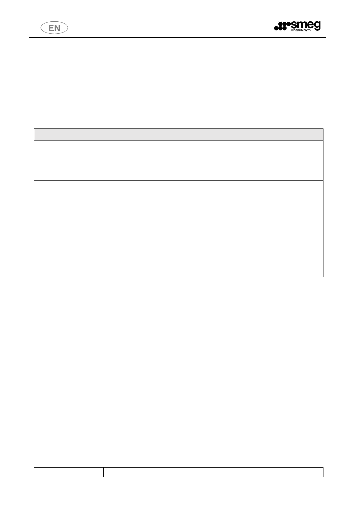
4.1 WD6010 and GW6010 - MACHINE WITH SWINGING DOOR
DEVICE VERSION
IMAGE
SINGLE DOOR MACHINE
There is a small lower door to access the detergent
compartment and the electricity supply disconnector.
DOUBLE DOOR MACHINE
IMPORTANT: in the double door version, on the load
side only, there is a lower door to access the detergent
compartment and the electricity supply disconnector.
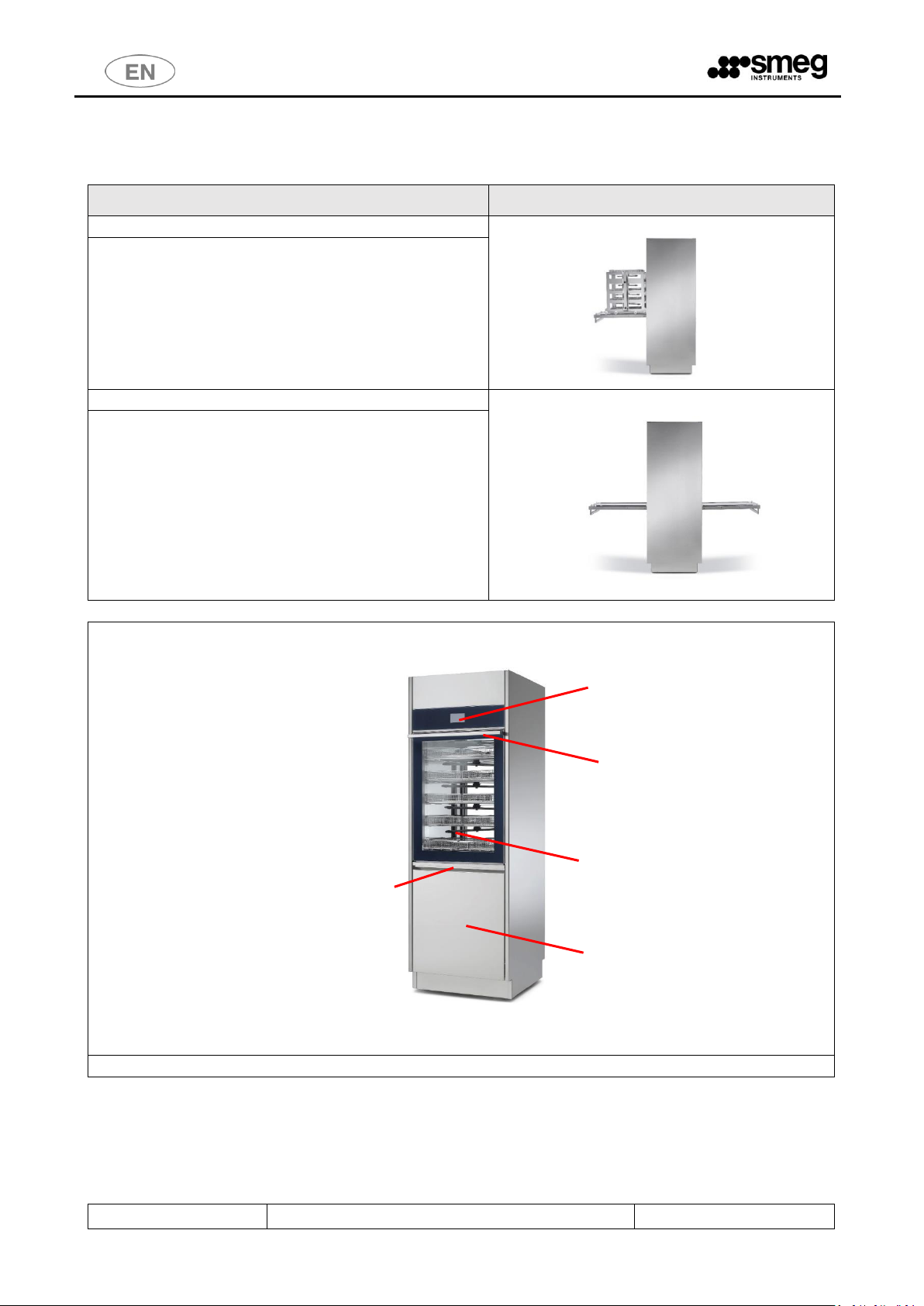
“LOADING” SIDE VIEW of the device.
TOUCH SCREEN
INTERFACE
DOOR HANDLE
GLASS DOOR TO
ACCESS THE WASH
TANK
LOWER DOOR TO
ACCESS DETERGENT
COMPARTMENT
LOWER DOOR
HANDLE
Page 11

USER MANUAL
GW6010 – GW7010 – GW7015
Page 11 - 138
“LOADING” SIDE VIEW of the device: the lower small door to access the detergent compartment has
been removed. The main starting switch can only be accessed with the door open.
In the double door version: the disconnector is only on the “unclean” side (“loading side”).
USB PORT: Near the disconnector is the USB port, to be used by authorized technicians, for
communication and device diagnostics. In the double door version: the USB port is only on the load
side.
“UNCLEAN” SIDE (“LOADING” SIDE) VIEW of the device, the lower small door to access the detergent
compartment has been removed. The detergent jerrycans are not visible, but the following can be seen:
- detergent suction lances with level sensor
- air filters for drying system (dryer)
- peristaltic pumps (pumps for liquid detergent dosage)
DETERGENT
JERRYCANS
MAIN STARTING
SWITCH
(DISCONNECTOR)
OPTIONAL
PRINTER
DETERGENT
PERISTALTIC
PUMPS
MAIN STARTING
SWITCH
(DISCONNECTOR
)
DRYER FILTERS
DETERGENT
SUCTION LANCES
Page 12

USER MANUAL
GW6010 – GW7010 – GW7015
Page 12 - 138
“UNCLEAN” SIDE (“LOADING” SIDE) VIEW of the device: the extracted cart is positioned on the door with
stops to limit movement.
CART EXTRACTOR
HOLDER MOUNTED ON
THE DOOR
WASHING CART
WATER MANIFOLD.
LOADING SIDE VIEW:
THE MANIFOLD MUST
WASHING CART
Page 13
USER MANUAL
GW6010 – GW7010 – GW7015
Page 13 - 138
4.2 WD7010 - GW7010, WD7015 – GW7015 – MACHINE WITH SLIDING DOORS
The sliding doors travel up and down to allow the operator access to the washing chamber for loading and
unloading of the instruments to be washed and disinfected.
Door opening and closure are activated by the user with the aid of the touch screen interface.
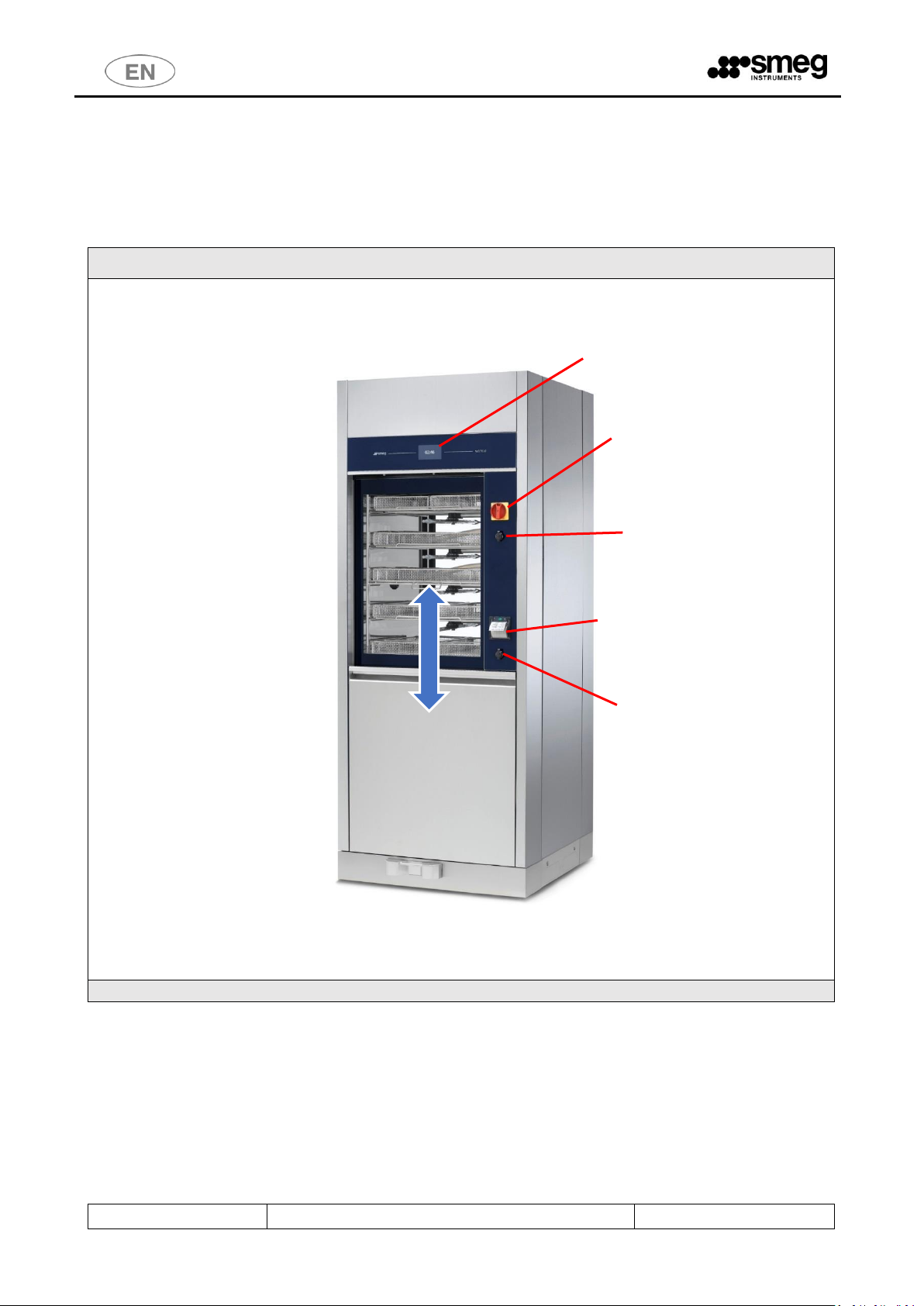
WD7010, GW7010
VIEW OF "UNCLEAN" SIDE (LOADING SIDE) of the device.
MAIN SWITCH ON-OFF
SWITCH
OPTIONAL
PRINTER
SAFETY KEY FOR SOLE USE
OF AUTHORISED
TECHNICAL STAFF
TOUCH SCREEN INTERFACE
USB PORT
Page 14

USER MANUAL
GW6010 – GW7010 – GW7015
Page 14 - 138
WD7015, GW7015
VIEW OF "UNCLEAN" SIDE (LOADING SIDE) of the device.
On the WD7015, GW7015 models the touch screen interface is on the side control panel.
MAIN SWITCH ON-OFF
SWITCH
OPTIONAL
PRINTER
SAFETY KEY FOR SOLE USE
OF AUTHORISED
TECHNICAL STAFF
TOUCH SCREEN INTERFACE
USB PORT
Page 15

USER MANUAL
GW6010 – GW7010 – GW7015
Page 15 - 138
Loading the chamber using the multi-purpose trolley.
Loading side – opening the door at the bottom gives access to:
- detergent jerrycan compartment (detergent jerrycans and intake nozzle)
- dryer air filters
- peristaltic pumps (liquid detergent dispensing pumps).
WARNING:
If the detergent compartment is open, the loading side door cannot be operated.
PERISTALTIC
PUMPS
DRYER FILTERS
DETERGENT
JERRYCAN
COMPARTMENT
Page 16

USER MANUAL
GW6010 – GW7010 – GW7015
Page 16 - 138
Unloading or "clean" side. Devices:
- "Mushroom" emergency stop button.
- Touch screen display.
Emergency stop button: allows the user on the unloading (or "clean") side to halt the machine. For
example, the button can be pressed if the user notices a malfunction that justifies stopping the current
cycle at once, or to halt movement of the doors.
The touch screen display on this side of the machine is read-only; the user can view the active screens
but not interact with the machine.
The only function enabled is door opening/closure.
The door can only be opened at the end of the cycle, and only if the wash cycle has been completed
successfully.
(The user may have halted the drying phase: in this case opening of the clean side door is possible).
WARNING: once the “emergency button” has been pressed, it must be rearmed (by turning it)
in order to restart the device.
The device should also be switched off and back on with the main switch before restarting
normal use.
EMERGENCY STOP
BUTTON
Page 17
USER MANUAL
GW6010 – GW7010 – GW7015
Page 17 - 138
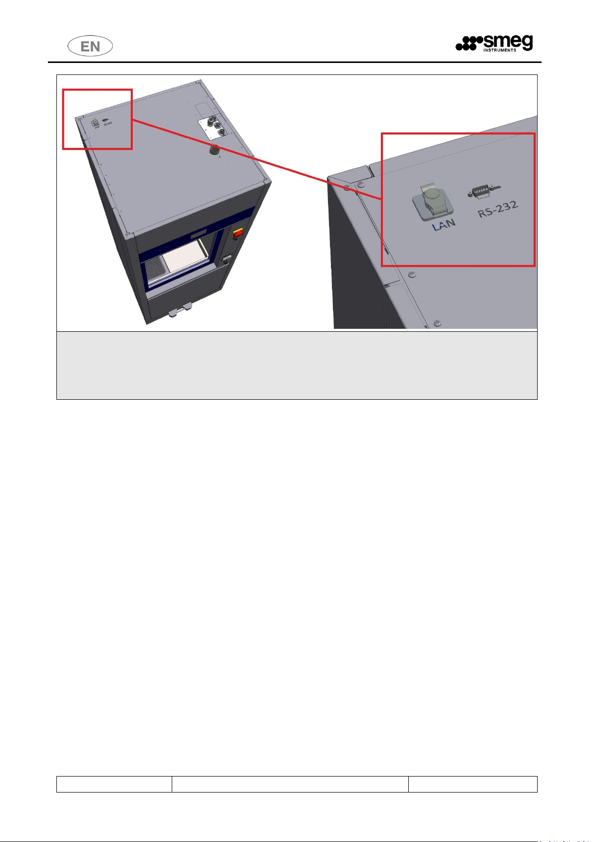
The following optional data communication ports are available on the TOP of the device:
- LAN PORT (optional) – for network communications using software supplied by the manufacturer
- RS232 optional for remote printer (the port can only be provided if the device is not fitted with the
thermal panel printer). See the specification for the optional “WD-PRINTEINK” printer.
For door positions, refer to the “Installation Requirements" documents.
Page 18
USER MANUAL
GW6010 – GW7010 – GW7015
Page 18 - 138
5 CONFIGURATIONS AND OPTIONALS
Symbols meaning
feature present
optional feature, installable on the model.
-
feature not present and not installable on the model.
WARNING – CHEMICAL AGENTS DOSAGE
Chemical agents dosage is performed through peristaltic pumps.
For each installed peristaltic pump the following control procedures are strongly encouraged:
1. Chemical dosage check– through flow sensors “flowmeter”;
2. Tank level check – through level sensors
Only when the control systems are installed can the device verify whether the dosage used complies
with the default setting and can warn the user of low dosage levels.
Control devices can be also installed upon use by technical staff authorized by the manufacturer.
Please contact your trusted dealer for more information and clarifications.
Notes on variants - Power supply:
Unless otherwise specified, the device is set for a power supply of three-phase plus neutral
with 400V between phases (400V 3N~). This configuration is also referred to as "standard" (“STD”).
Page 19
USER MANUAL
GW6010 – GW7010 – GW7015
Page 19 - 138
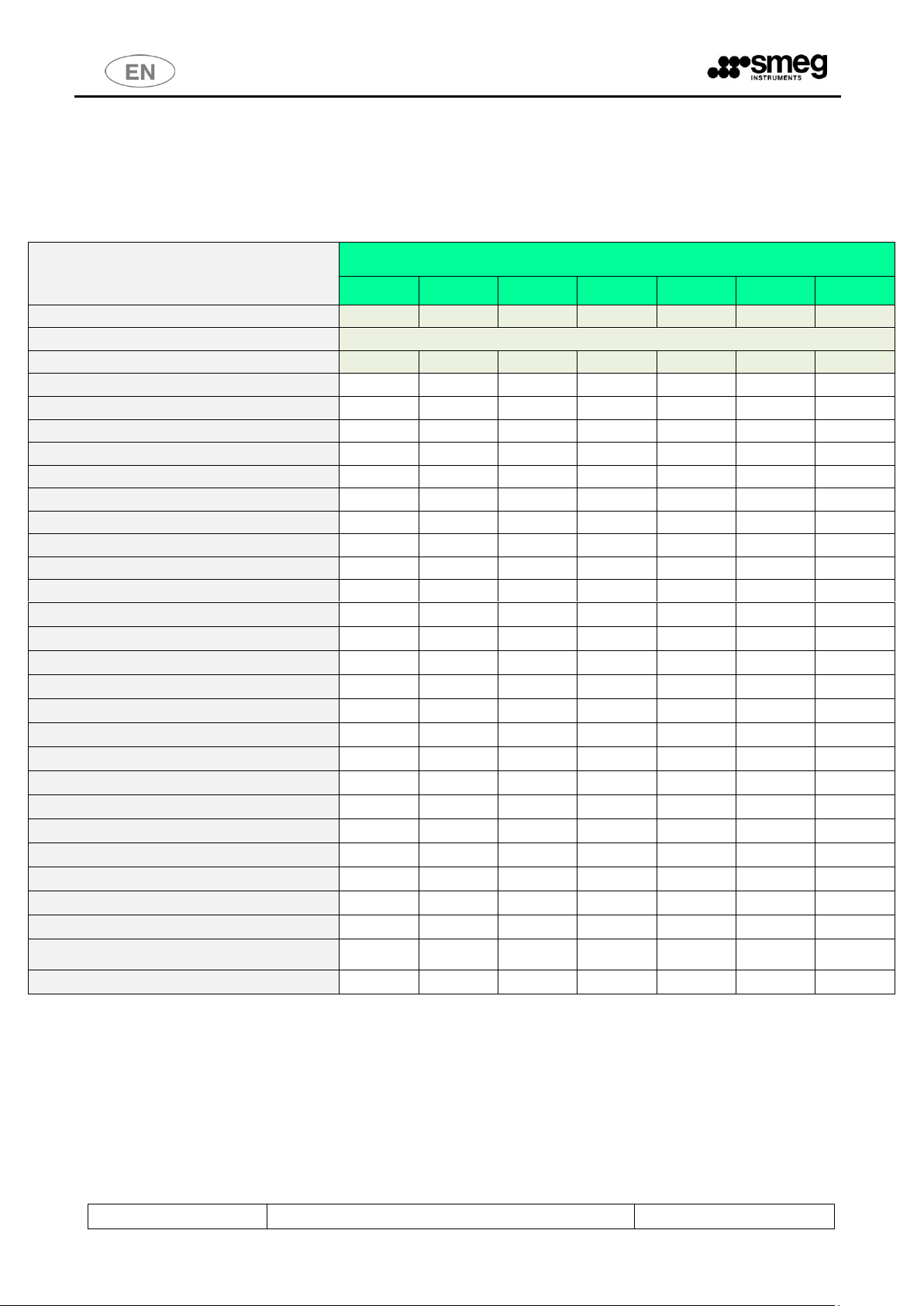
5.1 GW6010
The model is available in different versions, according to the installed elements. Common elements in all versions: tank material AISI316, tempered
glass doors, appearance and interface (touch screen), single washing pump with soft start, single dryer engine, floor drain, 3 water pipe
connections.
FEATURES
ID. CODE
860507
860512
860567
860576
860579
860596
860642
Model name
GW6010M
GW6010
GW6010M6
GW6010M36
GW6010-6
GW6010TM
GW6010MP
Door type (Drop down/ sliding)
Drop down
Doors number (tank access: single/ double)
Single
Double
Single
Single
Double
Single
Single
Detergent peristaltic pump P1
Acid neutraliser peristaltic pump P2
Optional peristaltic pump P3
Optional peristaltic pump P4
Check detergent dosage P1 – FM1
Check acid neutraliser dosage P2 – FM2
Check detergent dosage P3 – FM3
Check detergent dosage P4 – FM4
Check tank level P1 – SL1
Check tank level P2 – SL2
Check tank level P3 – SL3
Check tank level P4 – SL4
INTEGRATED printer
LAN connection
USB serial port
Demineralised water pump (pressure re-launch)
Integrated drain pump for wall drain
Drying absolute filter HEPA H13
Lighting tank kit “LED6010”
Vapours condenser
Warm water boiler
- - - - - -
Demineralized water boiler
- - - - - -
Conductivity check
Mains frequency
50 Hz
50 Hz
60 Hz
60 Hz
60 Hz
50 Hz
50 Hz
Notes for electrical connection
STD
STD
380-400V
3N~
220-230V
3~
380-400V
3N~
STD
STD
Various notes
- - - - - - Petrol
Page 20
USER MANUAL
GW6010 – GW7010 – GW7015
Page 20 - 138
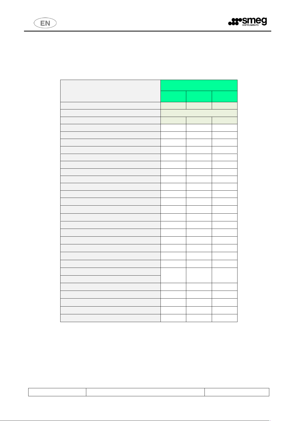
5.2 GW7010
The model is available in different versions, according to the installed elements.
Common elements in all versions: tank material AISI316, tempered glass doors, appearance and interface (touch screen), single washing pump with
soft start, single dryer engine, floor drain, 3 water pipe connections.
FEATURES
VERSION ID. CODE
860598
860599
860646
Model name
GW7010M
GW7010
GW7010T
Door type (Drop down/ sliding)
Sliding
Doors number (tank access: single/ double)
Single
Double
Double
Detergent peristaltic pump P1
Acid neutraliser peristaltic pump P2
Optional peristaltic pump P3
Optional peristaltic pump P4
Check detergent dosage P1 – FM1
Check acid neutraliser dosage P2 – FM2
Check detergent dosage P3 – FM3
Check detergent dosage P4 – FM4
Check tank level P1 – SL1
Check tank level P2 – SL2
Check tank level P3 – SL3
Check tank level P4 – SL4
INTEGRATED printer
LAN connection
USB serial port
Demineralised water pump (pressure re-launch)
Integrated drain pump for wall drain
Drying absolute filter HEPA H13
Lighting tank kit “LED6010”
Vapours condenser
Warm water boiler
-
-
Demineralized water boiler
-
-
Conductivity check
Mains frequency
50 Hz
50 Hz
50 Hz
Notes for electrical connection
STD
STD
STD
Various notes
- - -
Page 21
USER MANUAL
GW6010 – GW7010 – GW7015
Page 21 - 138
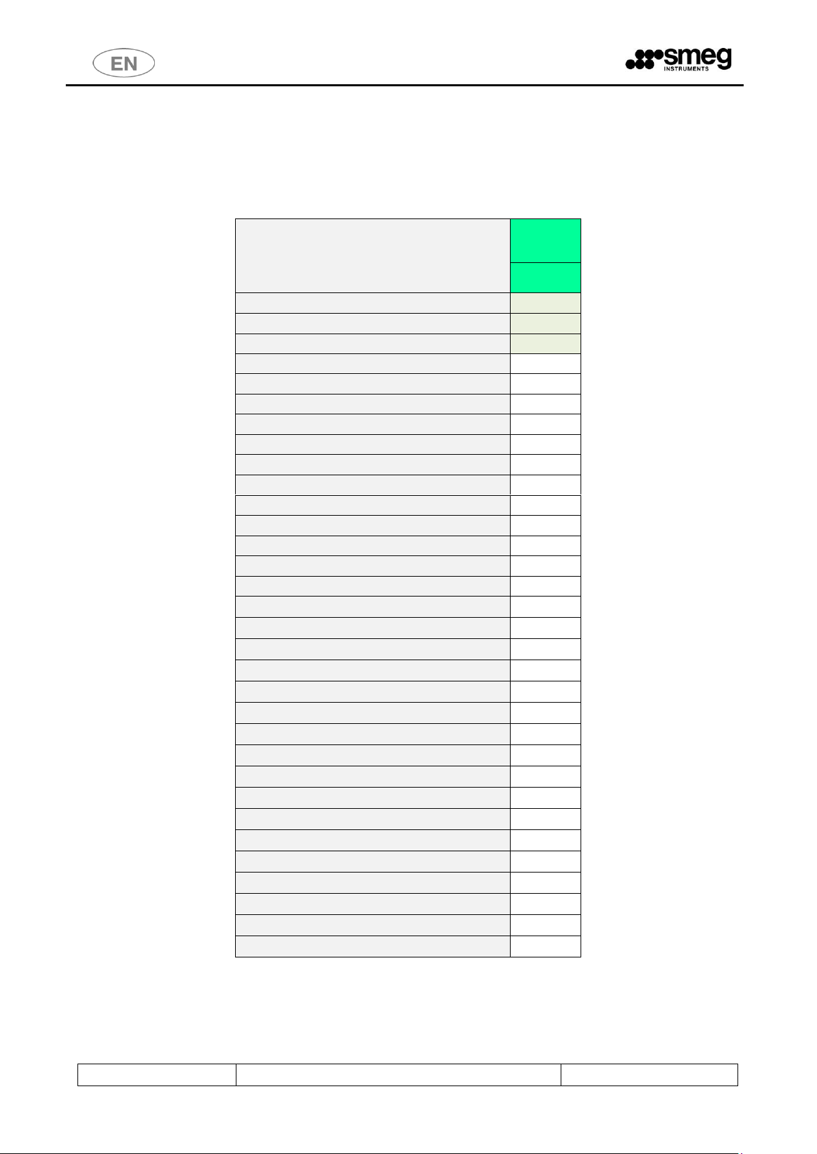
5.3 GW7015
The model is available in different versions, according to the installed elements.
Common elements in versions: tank material AISI316, tempered glass doors, appearance and interface (touch screen), double washing pump with
soft start, double dryer engine, floor drain, 3 water pipe connections., Door type: “Sliding”.
FEATURES
VERSION ID.
CODE
860681
Model name
GW7015
Door type (Drop down/ sliding)
Sliding
Doors number (tank access: single/ double)
Double
Detergent peristaltic pump P1
Acid neutraliser peristaltic pump P2
Optional peristaltic pump P3
Optional peristaltic pump P4
Optional peristaltic pump P5
Check detergent dosage P1 – FM1
Check acid neutraliser dosage P2 – FM2
Check detergent dosage P3 – FM3
Check detergent dosage P4 – FM4
Check detergent dosage P5 – FM5
Check tank level P1 – SL1
Check tank level P2 – SL2
Check tank level P3 – SL3
Check tank level P4 – SL4
Check tank level P5 – SL5
INTEGRATED printer
LAN connection
USB serial port
Demineralised water pump (pressure re-launch)
Integrated drain pump for wall drain
Drying absolute filter HEPA H13
Lighting tank kit “LED6010”
Vapours condenser
Warm water boiler
-
Demineralized water boiler
-
Conductivity check
Mains frequency
50 Hz
Notes for electrical connection
STD
Various notes
-
Page 22
USER MANUAL
GW6010 – GW7010 – GW7015
Page 22 - 138
6 SAFETY AND HANDLING PRECAUTIONS
6.1 KEY TO THE SYMBOLS USED IN THE MANUAL AND ON THE MACHINE
Below are the symbols used on the machine and in this manual, in compliance with par. 5.4.4.e IEC61010-2040:2005.
SYMBOL
MEANING
Particular attention must be paid when reading this.
This symbol indicates particularly important regulations or recommendations.
“ON” Power
Standardized symbol (5007 IEC 60417-1): it is on the disconnector (main switch) to indicate
connection to the electrical supply.
“OFF” Power
Standardized symbol (5008 IEC 60417-1): it is on the disconnector (main switch) to indicate no
connection to the electrical supply.
Manufacturer
The symbol appears on the product’s technical dataplate, accompanied by the name and address of
the medical device's Manufacturer.
(Symbol 5.1.1 ISO 15223-1, ISO 7000 no.3082)
Consult instructions for use.
The symbol appears on the product’s technical dataplate to indicate that users must consult the
instructions for use of the device.
(Symbol 5.4.3 ISO 15223-1, ISO 7000 no.1641)
Warning, danger: consult the manual.
This symbol is placed on the specific plate of the product to highlight that it is necessary to read the
manual before using the device.
This symbol is found next to the safety regulations as well.
Warning, warm surface.
This symbol is placed on the machine next to parts that can overheat and present burning hazards –
avoid any contact with parts next to the symbol. This symbol is also found in the manual to highlight
the safety regulations regarding burning hazards.
Warning, risk of electric shock.
The symbol is placed next to live parts – it is necessary to disconnect from the electrical supply source
before carrying out any operations on these parts. Avoid any contact with live parts if electricity is on.
Specific notes and regulations for Laboratory sector.
USB port – data communication and device setup
Transport, storing and unpacking regulations.
Biohazard.
Fire danger.
Page 23

USER MANUAL
GW6010 – GW7010 – GW7015
Page 23 - 138
SYMBOL
MEANING
The symbol of a “crossed out wheelie bin” (attachment IV directive 2002/96/EC): placed on the
specific label and package of the product: at the end of its service life, the product must be sent to
the disposal facilities for recovery and recycling, in compliance with the regulations in force in the
country where it is installed. Contact the specialized disposal installations.
Since January 2008, according to D.Lgs. 151/05, the management of WEEE (Waste of electrical and
electronic equipment) has been in the hands of manufacturers, whose duty is to plan and manage the
collection system; today it is possible to deliver the waste directly to the dealer for free, when
purchasing a device of the same type.
If purchasing a new equivalent device to replace the previous one, the disposal fees are at the
expense of the manufacturer of the new device.
At the end of its service life the machine might be contaminated, in particular the tank and water
circuit (e.g. end of service life caused by a malfunction which compromised the efficiency of the last
thermal disinfection cycle): use proper caution in the disposal operations. By making sure that this
product is disposed of properly, the user contributes in preventing any possible negative effects on
the environment and health.
The disposed device must be made unusable. Remove the power cable after unplugging it / after
disconnecting the cable from the power outlet.
CE marking.
The manufacturer guarantees compliance with the EU directives applicable to the product.
This symbol appears on the machine’s technical data label and in this manual.
Page 24
USER MANUAL
GW6010 – GW7010 – GW7015
Page 24 - 138
6.2 GENERAL RECOMMENDATIONS
MAXIMUM LOADING WEIGHT
Leaning or sitting on the device door when open may cause it to overturn with a
consequent danger for people. The main function of the door is not to support unnecessary
weight.
Devices with hinged doors: The The maximum weight that can be loaded on the door must
never exceed 60 kg.
Apart from the cart and the instrument baskets, the maximum weight of the load to be
treated must never exceed:
- GW6010, GW7010: 30 kg.
- GW7015: 45 kg
To obtain an optimal DRYING, the load to be treated must never exceed the maximum
recommended weight.
MULTI-PURPOSE TROLLEY
Sliding door devices: The multi-purpose trolley is a necessary device for the safe handling of
washing carts: for inserting the cart in the chamber and removing it.
Cart loading and removal operations performed without the aid of the multi-purpose
trolley constitute "misuse".
MALFUNCTIONS
In the event of malfunction (e.g. water leaks or unexpected operation) disconnect the device
from the electrical source and turn off the water taps. Refer to the “ALARMS” section of this
manual and, if necessary, contact the closest authorized Service Center.
The machine can be used only by staff properly trained on its functioning.
The machine tank was not designed for the operator to enter inside. The operator must
never enter completely inside the tank – this might compromise its safety (rif. 7.102
IEC61010-2-040:2005).
If the display (loading or unloading side) remains off or unresponsive even with the main
switch correctly set ON: do not touch the display as this may trigger unexpected operation
of parts of the device. Switch the device off using the main switch. Wait at least 10 seconds
after switching off before switching back on again.
Refer to the "ELIMINATION OF SMALL TROUBLES" section.
DOOR OPENING
The door is equipped with safety door-locking mechanism. Do not force the opening
manually. It is possible to unlock the door with the touch interface of the device and it is
permitted only when the washing or drying cycle is not in progress.
MACHINE WITH SLIDING DOORS
DO NOT APPROACH THE DOORS during automatic opening or closure.
The machine is fitted with doors which are opened/closed automatically.
Before enabling door opening/closure, check that other operators are not in a potentially
hazardous position.
Never attempt to open the door with a program running. The appliance's control system
prevents this for safety reasons. Never attempt to force the door open by hand.
The tops of the doors are fitted with pressure-sensitive edges: if the sensitive edge
encounters an obstacle while the door is in motion, door travel is first stopped and then
reversed to prevent crushing hazards.
Pressure-sensitive edges:
1. considerably reduce the crushing hazard for the user;
Page 25
USER MANUAL
GW6010 – GW7010 – GW7015
Page 25 - 138
2. reduce the possibility of closing the door with objects obstructing its travel.
The user must still take the greatest care during automatic operation of the doors, and
never:
1. allow any incorrectly positioned object to obstruct free travel of the doors;
2. touch moving parts.
The user is unable to open or close the door on the opposite side of the machine. Nor is it
possible to open both doors simultaneously.
The tank of the appliance is not designed for users to climb into, even for extraordinary
maintenance. The user must never climb into the tank - this might put his safety at risk.
DETERGENT COMPARTMENT DOOR
The bottom door, giving access to the detergent compartment, must be closed correctly to
enable automatic door opening and closure.
Do not open the bottom door during automatic door operation.
The bottom door must be correctly fitted and closed to allow use of the machine: safety
devices are installed to restrict operation of the machine if the door is not correctly
positioned.
INTERNAL TANK LIGHTING - OPTIONAL "LED6010” KIT
The appliance's lighting system is classified in the "EXEMPT" risk category (under the IEC
62471 standard): there is no photobiological risk in normal conditions of use.
DEMINERALIZED WATER
The demineralized water connection is required to install the device.
In case demineralized water is not available, it is the user’s responsibility to verify that the
quality of the water supplied to the device does not cause the deposit of mineral salts or
other substances.
FLAMMABLE SUBSTANCES
Do not introduce flammable substances to the device. Do not use flammable detergents.
Do not introduce alcohol or solvents such as turpentine, which might cause an explosion. Do
not introduce materials dirty with ash, wax or paint.
Page 26
USER MANUAL
GW6010 – GW7010 – GW7015
Page 26 - 138
CHEMICAL DISINFECTION
Warning: if possible, thermal disinfection is always more advisable than a chemical
disinfection process. According to regional regulations, the decontamination process with
chemical agents might be considered invalid by the responsible authorities, and can be used
only if the loaded items cannot bear the specific temperature of thermal disinfection.
The suggested washing and chemical disinfection cycles are specifically designed for the
recommended products and can be inappropriate with other chemical products. Do not use
products that were not specified by the manufacturer.
The authority responsible for the device and the decontamination process is also
responsible for the selection of the most appropriate treatment cycle.
CLOG WASHING AND DECONTAMINATION
The device where clogs are washed and decontaminated should be assigned to this specific
function, in order to avoid mistakes of use. Clogs require specific supports and specific cycles,
which are different from those used to process instruments.
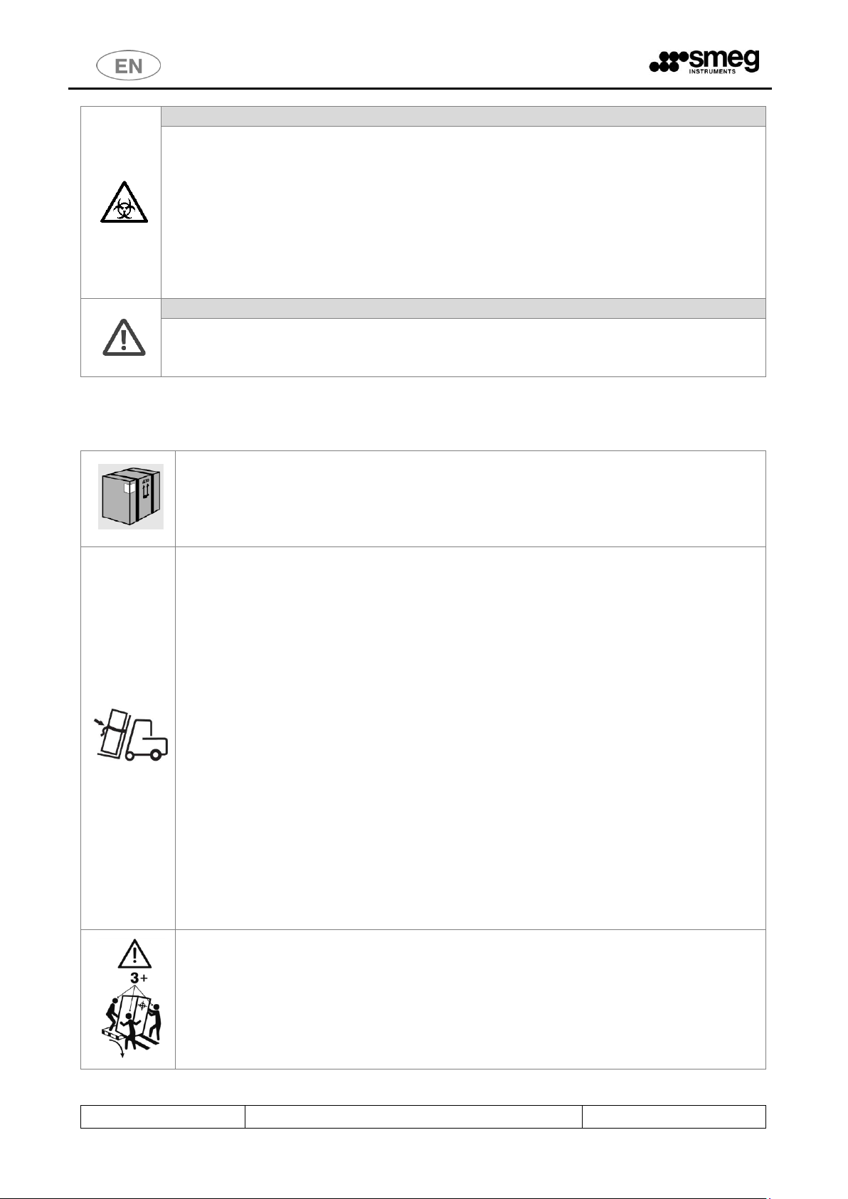
6.3 RECOMMENDATIONS FOR TRANSPORT
The machine is initially packaged: it is positioned and secured on wooden pallets,
wrapped in protective nylon for dust and water infiltrations and covered in cardboard.
Do not use devices which were damaged during transport.
STORING: The device must be preserved in a closed environment, not in the open air, in
temperature and moisture conditions similar to those specified for its functioning.
Transport of the machine to the place of its actual installation is at the client’s expense
ad requires a lift truck.
Refer to the product’s technical sheet to know its net weight and gross weight with
packaging.
When using the lift truck the product must be secured with belts to prevent it from
overturning in the event of braking.
Unpacking operations:
1. Take the external strapping off the packaging
2. Open and remove the cardboard and the nylon wrapping
3. Do not place the machine on its side
4. Remove the polystyrene corner protectors
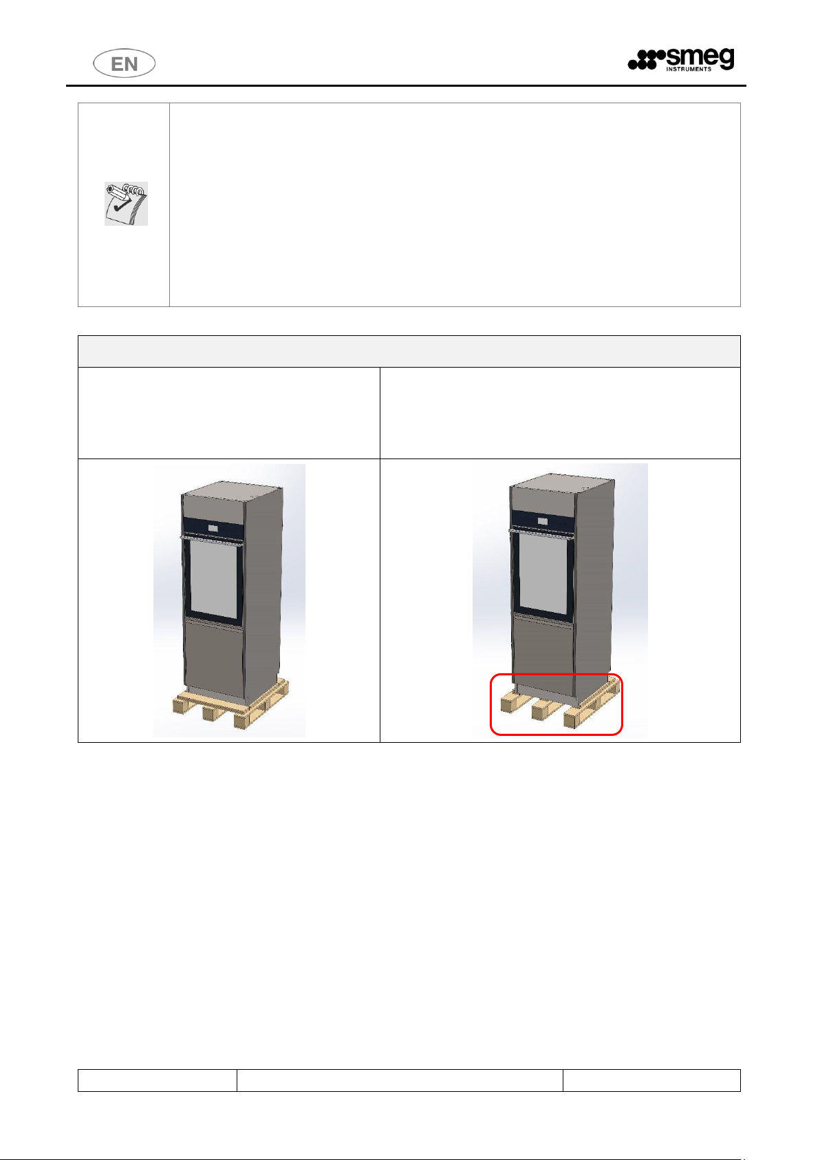
5. The machine base is fastened to a pallet to be lifted and transported. When the
machine is placed in the position for actual operation, the pallet holders, made with
self-tapping wood screws, must be removed.
6. Place the machine on a horizontal plane with a maximum gradient of 2°; level it
using the adjustable feet.
7. Do not place the machine on a flammable surface.
8. Do not use the door handles to transport the product.
Manual transportation of the product must be avoided as far as possible. The use of a tail
lift is recommended.
If manual transportation is necessary: involve at least 3 people or more to transport the
product. Use a “ramp” to take the device off the pallet more easily. Take care to secure the
ramp to the wooden pallet to prevent unexpected repositioning.
Page 27
USER MANUAL
GW6010 – GW7010 – GW7015
Page 27 - 138
POSITIONING THE MACHINE in the area of proper use
In the “double door” versions: the loading side is characterized by a small lower door which
gives access to the detergent compartment and the electric disconnector – be careful not to
confuse the loading side with the unloading side.
LEVELING
Once the machine has been placed, screw or unscrew the feet in order to adjust its position
and level it with the bubble level so that it is perfectly horizontal (maximum angular
tolerance permitted: 0.5°, corresponding to a maximum gap permitted on the extreme
points of the machine of about 5mm).
Levelling the device properly helps its correct operation.
Moving the machine, taking it off the pallet
1. Once the cardboard packaging has been removed, the
machine lies on a wooden pallet.
2. The front wooden holder can be removed to take the machine off
the pallet more easily. The structure of the machine is fastened to
the pallet: it must be unfastened to move the machine. The use of a
tail lift is recommended.
Page 28
USER MANUAL
GW6010 – GW7010 – GW7015
Page 28 - 138
6.4 ACCESSING AND REUSING THE DEVICE AFTER AN INCOMPLETE CYCLE
Instructions on the safety of the device in case of incomplete operation are given in compliance with the
par. 5.4.4.g and 13.1.102 IEC61010-2-040:2005.
In particular, these precautions are applied in the event the device is used to treat biologically
contaminated material.
WARNING
If a disinfection cycle is interrupted (by the operator or if an alarm arises): pay attention in
handling all instruments of the load inside the washing chamber.
The loaded items and internal parts of the machine might be infected/ biologically
contaminated.
Before handling the instruments or before any maintenance operation: start a complete cycle
of thermal disinfection or, if it is not possible to start a complete cycle, handle the instruments
cautiously (using the protection devices suitable for handling infected instruments, e.g. gloves,
smock).
WARM SURFACE DANGER
The machine operates a cycle of thermal disinfection using high temperature water, up to 93°C,
and detergents. If, in case of malfunction, the door is open and there is water inside the tank:
avoid skin contact, for burning and irritation danger due to the toxicity of chemical products.
Never touch the heating elements in the tank.
Contact authorized technicians in case of malfunction.
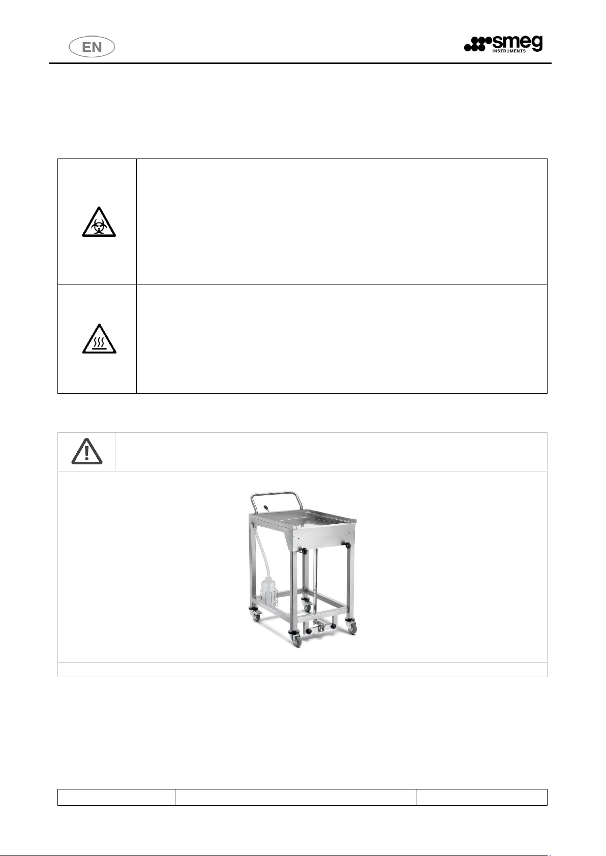
6.5 USE OF MULTI-PURPOSE TROLLEY
Sliding door devices: The use of a multi-purpose trolley is necessary for the safe transport the
washing cart inside and outside the machine.
Contact the authorized dealer for information about the most suitable multi-purpose trolley.
Sample image of the multi-purpose trolley for washing cart transport and device tending.
Page 29
USER MANUAL
GW6010 – GW7010 – GW7015
Page 29 - 138
6.6 DOOR OPENING
Machine with hinged doors: The machine is equipped with an automatic door lock system.
Machine with automatic sliding doors: the machine is equipped with an automatic door opening and
closure system.
Below is the procedure to open the door of the device to ease the access to the machine tank.
Connect the machine to the electricity source.
Switch the disconnector ON.
Check that the bottom door giving access to the detergent compartment is properly closed.
Wait for the device to start.
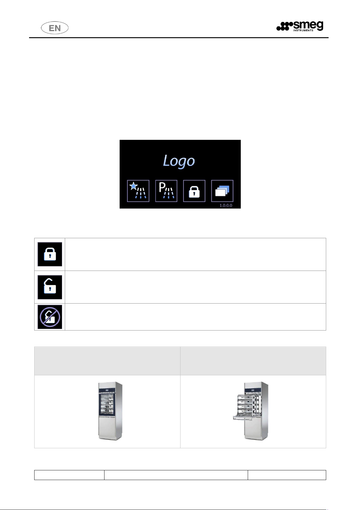
The device is equipped with a touch screen user interface, below is the home screen:
The actions correlated to the buttons differ slightly depending on the model being used.
6.6.1 GW6010
Button for DOOR UNLOCK. The closed lock means “locked door”. Please do not manually
force the door if the button is active.
“Double door” machine: a door can be unlocked only if the opposite side door is closed and
locked.
LOCK BLOCK: Button to activate door-locking mechanism.
The door must be closed in order to be locked.
If the lock is open, the machine is unlocked: it is possible to open the door by pulling the
handle.
Open door. If the door is open the door-locking and unlocking mechanism cannot work. The
display shows the symbol aside. Close the door manually to activate the locks.
To open the door without connecting the machine to electricity (i.e. in case of emergency or power failure,
it is necessary to use the manual unlock system (see next paragraph).
If the machine door is closed, it can be locked or
unlocked with the touch screen.
If the machine door is open, it is not possible to
activate / deactivate the safety door-locking
mechanism.
Page 30

USER MANUAL
GW6010 – GW7010 – GW7015
Page 30 - 138
DOOR OPENING
In the following images the door handle is highlighted.
The manual opening is allowed only if the door is unlocked. The door must be opened by pulling the handle from the center.
fig. 1 – View of Smeg 6010, the glass door to access the tank is equipped with a handle. The manual opening is allowed only if the door is unlocked,
being it equipped with automatic double electric lock. Do not force the opening of the door if it is locked.
DOOR CLOSING
Please note
Before closing the door,
Always make sure that the
washing trolley is
COMPLETELY INSERTED
inside the washing chamber.
Use the handle to close the door.
Before closing the door the washing cart must be completely inside the tank. Do not close the door if the
cart is extracted, even partially. Sequence of operations:
1. Let the cart slide completely inside the washing tank
2. Close the door of the device using the handle
3. When the door is closed, it is possible to lock the door using the touch interface “lock” symbol.
Page 31

USER MANUAL
GW6010 – GW7010 – GW7015
Page 31 - 138
6.6.2 GW7010 – GW7015
“PADLOCK” button for access to the door operating or "Door Control" screen.
DOOR LOCKED ICON - the locked padlock means "door locked”.
Never force the door open manually if the button is in this status.
Machine with "double door": A door can only be opened if the door on the other side is
locked.
DOOR OPEN ICON - The open padlock means "door open”.
Page 32

USER MANUAL
GW6010 – GW7010 – GW7015
Page 32 - 138
Icons – buttons in the Door Control screen, sch.1300.
OPEN: Button for opening the sliding door (DOWNWARD travel).
CLOSE: Button for closing the sliding door (UPWARD travel).
OPERATION NOT POSSIBLE: the icon informs the user that the automatic operation
requested is not possible: this occurs if
- the door on the other side is open,
- the door is in motion,
- the bottom door, giving access to the detergent compartment, is open.
Door opening button
Icon – door 1 current
status, unclean side
Icon – door 2 current
status, clean side
The blue bar indicates the
active side for the user.
Page 33

USER MANUAL
GW6010 – GW7010 – GW7015
Page 33 - 138
Machine with sliding doors - detailed views
Closing the inner panel covering
the detergent compartment.
Closing the bottom door.
Machine correctly closed.
N.B.: The bottom door, giving access to the detergent compartment, must be closed correctly to enable
automatic door operation.
6.7 MANUAL DOOR UNLOCK
Only if necessary, or in case of malfunction or power failure, it is possible to open the machine manually
using the dedicated device. When the door is opened, the devices that could be dangerous for the operator
(such as the washing pump) are automatically blocked.
At any rate, all precautions must be observed. To learn more about the precautions in detail, refer to the
paragraph called ACCESSING AND REUSING THE DEVICE AFTER AN INCOMPLETE CYCLE.
Contact the authorized technicians for detailed information on how to unlock doors manually.
Page 34

7 OPERATING PROCEDURES
After the device has been correctly installed, it must be set for operating use. Execute the following steps:
-Set current date and time.
- Set desired language.
- Prepare the detergent, neutralizer, and any other chemical agents to be used.
-Upon installation an authorized technician is required to activate the peristaltic pumps manually so that
the detergent charging hoses are correctly filled.
-Run, empty load, a complete program including thermal disinfection.
Once these steps have been successfully completed, the machine is ready for use.
7.1 Access to detergent compartment
Front view of the device – loading side: for both hinged and sliding door machines, the steel bottom door giving
access to the detergent compartment is underneath the main door of the tank.
The detergent compartment door has a handle allowing it to be opened by hand.
The detergent compartment is able to take up to:
- 6010 and 7010: N.3 x 5 litre jerrycans plus a N.1 x 2 litre bottle
- 7015: N.3 x 5 litre jerrycans plus N.2 x 2 litre bottles.
(refer to the chemical products and jerrycans supplied by the device's manufacturer).
Frontal view of the device. Under the main door of
the tank there is a steel door that opens to the
detergent compartment.
The detergent compartment door is equipped with a handle
for manual opening.
Page 35

USER MANUAL
GW6010 – GW7010 – GW7015
Page 35 - 138
7.1.1 WD6010 - GW6010
Besides the detergent jerrycans, the lower
door opens to the red main switch
(“disconnector”) and to the printer (optional).
Detailed view: inferior detergent compartment, electric
disconnector, printer.
Page 36

USER MANUAL
GW6010 – GW7010 – GW7015
Page 36 - 138
7.1.2 WD7010 - GW7010 – WD7015 – GW7015
ATTENTION
For all machines with sliding doors, opening of the detergent compartment disables the
automatic door opening system.
Always make sure that the two doors giving access to the detergent compartment are
properly closed before giving the command to open the loading side door.
To access the detergent compartment, open the
outer bottom door - loading side.
There is an additional metal panel protecting the jerrycan
compartment. This must be removed to access the jerrycans.
7.2 USE OF DETERGENTS
The machine is equipped with automatic devices for liquid detergent dosage.
1. Pump P1, liquid detergent dosage, neutral or weakly alkaline
2. Pump P2: acid neutralizer dosage.
3. Pump P3: optional.
4. Pump P4: optional.
5. Pompa P5: optional and installable only on 7015.
DOSAGE DEVICE
Standard Configuration
Pump function on
machines hospital sector -
WD
Pump function on
Laboratory device - GW
Color key
P1
Alkaline Detergent
Alkaline detergent
White
P2
Acid Neutralizer
Acid neutralising agent
Red
P3
Disinfectant
Optional - degreaser
Blue
P4 Lubricant
Optional – antifoam
Green
P5
Enzymatic detergent
Additional detergent
Yellow
Key: present characteristic, Optional characteristic, - non installable characteristic
WARNINGS
In case there are no level sensors in the jerrycan, periodically check the product level in the jerrycans
/ bottles to avoid running empty cycles.
During installation and after replacing the jerrycan, run an empty “SERVICE” program to load the
liquid. This refills the duct that runs from the jerrycan to the pump and ensures correct product dosage
in the following wash cycles.
Page 37

USER MANUAL
GW6010 – GW7010 – GW7015
Page 37 - 138
7.2.1 LIQUID DETERGENT SUCTION SYSTEM
Configuration with LEVEL SENSOR.
1. Suction lance with integrated level sensor and a cone-shaped rubber support for positioning in the
jerrycan.
2. Flexible silicone tube to connect the suction hose to the peristaltic pump.
3. Detergent suction filter, mounted directly on the lance suction cannula.
WARNING
The label attached to the suction tube must be congruent with the type of detergent used.
Please refer to the colour code above.
Connection mistakes impair the efficiency of the process and may damage parts of the circuit.
Any error leading to improper connection of the detergent suction system voids the warranty
agreement between the involved parties.
The suction tube is equipped with a suction filter. Make sure that the filter is always there and
placed correctly in order to preserve the good functioning of the detergent inflow system. Check
periodically that the silicone tube is adequately secured to the suction tube and that there is no
leakage.
fig. 2 – STANDARD Configuration of detergent suction device. Place of detergent suction tube in the jerrycan. Fit the rubber cap to the jerrycan
opening for optimal placement. The tube is equipped with a suction filter.
Page 38

USER MANUAL
GW6010 – GW7010 – GW7015
Page 38 - 138
8 DETERGENTS
Detergent is one of the most important components to a good washing process.
The manufacturer guarantees excellent washing results with the recommended products.
Please contact the manufacturer for recommendations about the detergent types that most suit your
needs, and their proper use.
The effectiveness and the proper functioning of the machine cannot be guaranteed when
non-recommended detergents are used.
WARNINGS
Always follow the REGULATIONS provided by the detergent MANUFACTURER, in
particular for what concerns the ADVISED DOSAGE and the proper TEMPERATURE.
Safety information on dosage, provided in accordance to 5.4.4.s IEC61010-2-040:2015.
Please refer to the product instructions and material safety data sheets.
The data sheets are available on request.
Note: third pump P3 and fourth pump P4 are optional accessories.
Advised detergents for GW products – Laboratory sector
P1 – Alkaline detergents
DETERLIQUID D
Liquid alkaline detergent. 10 litre container.
DETERLIQUID D2
Liquid alkaline detergent, phosphate-free.
5 litre container.
DETERLIQUID SP
Liquid alkaline detergent for water and pharmaceutical analysis, phosphate-free. 5
litre container.
P2 – Acid neutralizers
ACIDGLASS P
Liquid acid neutraliser for laboratory glassware. 5litre container.
ACIDGLASS P2
Liquid acid neutraliser for laboratory glassware. 5litre container.
ACIDGLASS C2
Neutralizing acid detergent. 5-liter container, phosphate-free.
P3 – Optional
Please contact the manufacturer for suggestions about the best additive, according to use.
P4 – SPECIAL ADDITIVES
F1S
Silicon defoaming additive for petrol cycles, phosphate-free.
1 litre container.
P5 – Optional
Please contact the manufacturer for suggestions about the best additive, according to use.
Page 39

USER MANUAL
GW6010 – GW7010 – GW7015
Page 39 - 138
DETERGENT GENERAL WARNINGS
HANDLE THE DETERGENT JERRYCANS WITH CARE
Warning: detergent may be TOXIC.
Please consult the product material safety data sheets.
Once finished, the exhausted tank must be replaced with a new one of the same product.
When the jerrycan is being replaced, particular care should be made not to overfill new
containers, in order to avoid overflow when inserting the suction devices.
Protective gloves are recommended during product replacement and jerrycan transfer
operations, as well as suction devices insertion. Information provided in accordance to
5.4.3.o, 5.4.4.n, 5.4.4.q IEC61010-2-040:2015.
EMERGENCY MEASURES IN CASE OF CONTACT WITH DETERGENT
Prescriptions in accordance with par. 5.4.4.p IEC61010-2-040:2015.
Take off contaminated clothing and set them aside in a safe place.
Skin and eye contact: rinse affected area immediately with plenty of water. If possible, apply sterile
gauze. Please consult a doctor.
If swallowed: rinse mouth with plenty of water. Consult a doctor immediately.
DETERGENT MATERIAL SAFETY DATA SHEETS
The SAFETY DATA SHEETS of the detergents should be kept:
1. In proximity to the place where detergents are stored.
2. In proximity to the device.
In easily accessible locations.
Updated safety data sheets should be regularly (e.g. once a year) requested.
The data sheets will be provided by the manufacturer upon request.
DISPOSAL
Information provided in accordance with par. 5.4.4.L IEC61010-2-040:2015.
DISPOSAL of possible product residues and containers (bottles and cans): please refer to the safety
data sheet of the product, in the "DISPOSAL CONSIDERATIONS" section.
The person responsible for the equipment must proceed with the disposal of the detergents residues
and their containers in accordance to the existing national or local standards.
FLAMMABILITY
Always refer to the material safety data sheets of the detergents to assess product flammability.
Never use flammable products in a car.
Page 40

USER MANUAL
GW6010 – GW7010 – GW7015
Page 40 - 138
9 LOAD PREPARATION FOR WASH CYCLE AND DISINFECTION
Regulations on loading modalities are provided in compliance with 5.4.4-k IEC61010-2-040:2015.
An effective washing begins in the load preparation phase: the load must be adequately placed in the
appropriate supports.
Before loading the wash elements into the designated wash baskets, it is necessary to
eliminate any coarse residue resulting from previous activities, through the appropriate
wash, treatment, and rinse phases.
The load must be properly placed to prevent wash elements from overlapping as well as
the formation of “grey areas”; all areas of the wash load must be reached by the spray arm
and/or injectors’ water in the wash and rinse phases.
The open side of the container must face downward so that the load elements are correctly
washed and dried at the end of the cycle.
The machine is supplied without washing carts.
Please refer to the washing cart manuals for instructions on proper use.
The operator must avoid direct contact with the dirty load.
Use extreme caution by wearing all personal protective equipment both before and after
the treatment.
Before processing glassware or other objects in the instrument washer, check the
manufacturer instructions to verify that they are approved for automatic treatment in
the thermal disinfector and check the compatible maximum washing temperature.
Avoid introducing glassware with labels applied on: the labels, detaching during the
washing, can obstruct the washing filters, compromising the good success of the cycle.
Warning
Washing carts are never symmetrical; they contain a manifold for the cart’s water supply. The cart must
be placed so that the manifold is on the right side of the machine (as viewed from the unclean side).
Below: hinged door machine, correct washing cart loading position.
“UNCLEAN” SIDE or
“LOADING” SIDE
“CLEAN” SIDE or
“UNLOADING” SIDE
Page 41

USER MANUAL
GW6010 – GW7010 – GW7015
Page 41 - 138
Below: sliding door machine, correct washing cart loading position. Looking at the device from the
loading side ("unclean" side), the cart manifold is on the right-hand side of the machine.
The manifold must
be placed on the
right side.
Page 42

USER MANUAL
GW6010 – GW7010 – GW7015
Page 42 - 138
10 BASIC OPERATIONS
10.1 HOME SCREEN – ID 1.0.0.0
The device is provided with a touch screen user interface.
Button to enter the FAVOURITE PROGRAMS MENU (last 4 different programs used).
Button to enter the COMPLETE MENU of WASHING CYCLES.
Door control – door lock/unlock, open/close button.
The button icon changes depending on the door's status (padlock closed means door locked
closed, padlock open - door open).
SETUP: Button for settings and diagnostics options.
10.1.1 DOOR CONTROL - MACHINES WITH HINGED DOORS
Button for DOOR UNLOCK. The closed lock means “locked door”. Please do not manually
force the door if the button is active.
LOCK BLOCK: Button to activate door-locking mechanism. The door must be closed in order
to be locked.
10.1.2 DOOR CONTROL - MACHINES WITH SLIDING DOORS
Door control screen access button.
Press this button to access the Door control screen.
A user can only operate the door on his own side, and the "clean side" door can only be opened if the
wash cycle has been performed and completed successfully.
DOOR LOCKED ICON - The locked padlock means "door locked”.
Never force the door open manually if the button is in this status.
Machine with "double door": A door can only be unlocked if the door on the other side is
locked.
Page 43

USER MANUAL
GW6010 – GW7010 – GW7015
Page 43 - 138
DOOR OPEN ICON - The open padlock means "door open”.
OPEN: Button for opening the sliding door (DOWNWARD travel).
CLOSE: Button for closing the sliding door (UPWARD travel).
STOP: button for halting automatic movement of the sliding doors.
Door status
Screen 1300 provides information about the status of the doors. There are three possible stages for each
door:
1. Closed – door at closed limit stop position. The door can only be opened.
2. Open – door at open limit stop position. The door can only be closed.
3. Intermediate – door in an intermediate position between the two limit stops. The door can only be
closed.
The door can only be in an intermediate position if opening or closure has not been correctly completed.
The possible causes are:
1. Power failure with door in motion,
2. Travel halted by tripping of safety devices, e.g. due to opening of the detergent compartment door.
Door opening button
Page 44

USER MANUAL
GW6010 – GW7010 – GW7015
Page 44 - 138
10.2 PROGRAMS COMPLETE MENU - ID.1.1.0.0
Use the arrow-indicators to the right of the screen (UP/DOWN) to browse the menu entries.
Touch the preferred program button to open PROGRAM START. Click the “Home” button on the upper-right corner to
return to the previous screen.
Door lock/unlock button is also active on the main screen.
10.3 FAVOURITE PROGRAMS MENU - ID.1.1.0.0
The screen displayed is similar to the COMPLETE PROGRAMS MENU.
The last 4 programs chosen by the user are displayed; menu scroll options do not appear since the menu consists only
of 4 entries.
At the top-right: reference button to return to the complete programs menu.
10.4 PROGRAM START - ID. 1.1.1.0
On the screen the main parameters of the selected program are summarized.
Press the bottom right button, “START”. The program begins.
In the top right window, main cycle parameters are reported (Ao and maximum temperature). These are always visible
throughout the cycle execution.
Page 45

USER MANUAL
GW6010 – GW7010 – GW7015
Page 45 - 138
10.4.1 EXTERNAL PERIMETER BUTTONS AND DATA.
PROGRAM NAME
UNIVOCAL ID
PROGRAM
“HOME” to go back to the previous
screen.
“LOCK/UNLOCK” to lock or unlock
the door.
“START” to start the program
ID screen
N. machine
cycles
Date and time
“OPTIONS” to select cycle options
in action.
Page 46

USER MANUAL
GW6010 – GW7010 – GW7015
Page 46 - 138
10.4.2 “INTERNAL PERIMETER” SCREEN DATA
10.4.3 SELECTED CYCLE OPTIONS – ID. 1.6.1.0
Only staff well-trained in choosing the wash cycle and related options can have access to the following
functions.
Through the button on the screen of the selected cycle it is possible to move on to “Cycle options” screen
to activate and regulate some options for the ongoing cycle.
Since 7.16.0 CPU Master version software (July 2017), the screens dedicated to the selected program
options (1610) have been modified.
In detail, you have the following new options for the cycle:
1. select/deselect the conductivity check “Cond. Check”
2. save the drying phase and conductivity check settings, to make them permanent for the selected
cycle;
3. the existing Delay start and No demi water options are still available: these options apply to the
current cycle and, given their meaning, cannot be saved as permanent settings.
Selected program 1110.
Select the "gear pair" icon on the right to enter the
Program options.
Detergent pumps
activated by the
cycle and related
dosages
Button to browse the list
of activated pumps and
dosages
Tmax: highest wash temperature of the
cycle
Ao: Ao value which characterizes the
cycle
The values are “0” if they are not
defined for the selected cycle.
N. of cycle
phases
Drying: target
temperature and
duration of the phase
in minutes.
Estimated cycle
duration
Icon that shows the
selected cycle type
Page 47

USER MANUAL
GW6010 – GW7010 – GW7015
Page 47 - 138
Program options - screen 1610.
To do so, either check or uncheck the “Cond. Check”
box.
Use the “Save” button on the right to confirm this
option for the program in question.
Save button details - New button for saving changes to
the program.
Temporary options - Press the down arrow to access
the temporary options for the current program.
For the preceding versions of firmware (before july 2017), the cycle options were:
1. Drying. The drying option is labelled with the symbol “fan”: it is possible to exclude the drying
phase from the cycle or to decrease target temperature and duration, within the limits fixed by the
device.
2. Postponement: it is possible to set up a postponed cycle start, in case the unloading operations of
the machine must be synchronized with user availability.
3. Exclusion of purified water: by selecting this option, cold water will be used only during the
following cycle instead of purified water.
The option is activated by ticking the related box.
Selected option may be regulated through the +/-buttons, located on the right side.
The data is effectively changed by touching the CONFIRMATION button, located at the bottom right
corner of the screen.
Page 48

USER MANUAL
GW6010 – GW7010 – GW7015
Page 48 - 138
10.4.4 CYCLE START – “USER CHECK” FUNCTION ACTIVE
If the superuser has activated the “User check” function requiring the user to be identified, in order to start the cycle
users must:
1. Be on the list of users enabled by the superuser.
2. Select their user ID (e.g. User_01) – using the “Right arrow" button.
3. Enter their passwords and confirm.
10.4.5 NOTES
Regarding thermal disinfection cycles versus chemical disinfection cycles, see suggestions from the product standard
ISO EN 15883.
Extracted from ISO EN 15883-1:
“4.1.5 Disinfection is specified by reference to time and temperature for thermal disinfection or as time,
Temperature and concentration for chemical disinfection.
Whenever practicable, thermal disinfection is preferred. Thermal disinfection processes are more easily
controlled and avoid the hazards to staff, patients and the environment that can occur through the use of
chemical disinfectants.”
Regarding significance of the Ao parameter, see Annex B, EN ISO 15883-1.
The parameter expresses “comparative lethality of moist heat processes”, and associates a numeric value with thermal
disinfection effectiveness. A0 concept — “Comparative lethality of moist heat processes”
10.5 PROGRAM UNDER WAY - 1.1.1.3
During an ongoing cycle, the only possible action for the user is the cycle interruption, through the bottom right “STOP”
button.
The screen summarizes relevant data recorded by temperature probes, peristaltic pumps doses, remaining time. Next
to the “CLOCK” icon, the remaining cycle time is displayed. The icon flashes while cycle is active.
“CONFIRMATION” button to
confirm data and go back to the
screen of the selected cycle.
Touch the box with numeric value
to activate regulation.
Page 49

USER MANUAL
GW6010 – GW7010 – GW7015
Page 49 - 138
ICON
PHASE TYPE
- Prewash -
.Structure: phase without any activation of heating elements or addition of chemical agents..
.Applications: used to remove larger spots and therefore to limit the formation of suds in the
following phases.
- Simple wash -
.Structure: Basic wash cycle that removes dirt from the load elements, accomplished through
appropriate dosage of chemical elements at controlled temperatures.
.Applications: this phase washes the load without disinfecting it.
- Wash with chemical disinfection -
.Structure: wash phase characterized by application of chemical elements with a bactericidal
effect on the load elements.
This cycle is generally not associated with any thermal disinfection phases.
.Applications: used to wash elements that do not need any thermal disinfection or are
sensitive to elevated temperatures. This cycle washes and disinfects the load chemically.
.Cautions: Whenever practicable, thermal disinfection is preferred. Thermal disinfection processes
are more easily controlled and may prevent hazards to staff, patients and the environment that can
occur through the use of chemical disinfectants.
N. current phase
of the cycle
During drying phase:
Value interpreted by
the TL probe
Icon that shows the
current cycle type:
drying
“STOP” button to
interrupt the cycle
Temperature
measured by TL
working probe
Temperature measured
by TCL control probe
Tmax: maximum wash temperature of
the cycle
Ao: Ao value that characterizes the
cycle.
N. current phase
of the cycle
Ao, current value of
the parameter
Remaining time of
the current cycle
Icon that shows
the cycle type
“STOP” button to
interrupt the cycle
Page 50

USER MANUAL
GW6010 – GW7010 – GW7015
Page 50 - 138
ICON
PHASE TYPE
- Thermal disinfection -
.Structure: phase in which, through combination of time and temperature, the chosen
parameter value “Ao” can be reached, and load elements are disinfected. The thermal
disinfection phase is preceded by cycles to remove dirt from the load elements and properly
prepare it for the chemical disinfection phase.
This cycle is generally not associated with any chemical disinfection phases.
.Applications: used to wash elements that can withstand elevated heat treatment (reference
target values are 80°C, 90°C, 93°C). The phase thermo disinfects, with the Ao parameter value
dependent on the temperature reached and cycle time.
.Cautions: Whenever possible, thermal disinfection is preferred. Thermal disinfection processes
are more easily controlled and may prevent the hazards to staff, patients and the environment that
can occur through the use of chemical disinfectants.
- Drying -
.Structure: phase characterized by air target temperature and duration expressed in minutes.
.Applications: load drying.
- Service -
.Cycle structure: “free” structure, cycle functional to maintenance operations, only accessible
to authorized technical staff.
.Applications: cycle for technical staff use. This cycle does not handle the load in the washing
drum, but it is functional to technical staff operations, e.g. water circuit and detergent circuit
replenishment. This cycle may also be used as test cycle that rapidly verifies the proper
operation of the machine parts.
.Cautions: the cycle cannot be activated to handle the load in the washing drum.
Page 51

USER MANUAL
GW6010 – GW7010 – GW7015
Page 51 - 138
10.6 SUBPHASES IN PROGRESS
The information regarding the cycle in progress is supplied with graphic icons, indicating the current
subphase. The icons are located in the lower right part of the display.
Table of icons and the indicated subphases
Cold water loading
Hot water loading
Demineralized water loading
Cold + Hot water loading
Loading of
cold water
in progress
Loading of
hot water in
progress
Loading of
demi water
in progress
Loading of
cold + hot
water in
progress
Heating active
Boiler hot water
Boiler demi water
Boiler hot + demi water
Drainage
heating
element
active
Heating
hot boiler
active
Heating
demi boiler
active
Heating
hot and
demi
boiler,
both
active
Tank
drainage
10.6.1 PROGRAM IN PROGRESS “DISPLAY EASY”- 3.4.2.1
It is possible to set up a simplified visualization of the cycle in progress, identified as “Display Easy” (see the
section of menu “Setup”).
In the simplified visualization of the cycle in progress, the display only shows:
1. The name of the program
2. The time of the cycle in progress (time left or current, depending on the settings).
3. The progress bar
Touching the display, with the “Easy” visualization active, it will show the standard visualization for a few
seconds; here it is possible to monitor a greater amount of parameters.
Page 52

USER MANUAL
GW6010 – GW7010 – GW7015
Page 52 - 138
10.7 COMPLETED PROGRAM - 1.1.1.4
At the end of the cycle, the screen displays an icon to indicate the status of the completed cycle (“END – Cycle complete”)
relevant data about the cycle performed.
It is possible to execute only the following options:
1. Unlock the door through “lock/unlock” button to open it and extract load – ordinary operation.
2. Go back through the “Home” button to select a further additional cycle without unlocking or opening
the door – only useful in case a load must undergo additional consecutive cycles.
3. Last cycle reprint button.
This function, which reprints the last cycle, is available from July 2017 (Master CPU firmware
release 7.16.0), and it is only active if the printer is present and enabled.
The function reprints a completed program if the previous printout was incomplete, due to
lack of paper, for instance.
If the printer is enabled but not present on the machine, the button is still present and
enabled, but has no effect.
END
CYCLE
ICON
MEANING
The cycle was successfully completed.
The washing part of the cycle was successfully completed, but the drying was interrupted or
some problems occurred during the drying.
The cycle failed. Anomalies occurred during operation or the user forced the cycle to stop.
Icon that shows the
end of the cycle.
Page 53

USER MANUAL
GW6010 – GW7010 – GW7015
Page 53 - 138
11 SETUP OPERATION - 1.4.0.0
The device has a setup modality to modify functional parameters.
The setup menu consists of entries that regulate the parameters of the machine, start maintenance and
control operations on the device.
Access to these menus is password-protected and restricted to use only by approved technical staff.
Between the basic user and technical staff there is an intermediate level, called “superuser”.
The superuser consists of the authority responsible for the device in the structure where it is installed.
The superuser level password is shared with the individual in charge of the device.
Depending on the firmware versions actually installed, some aspects of the device setup menu may be
different from that described in this manual. Contact authorised engineers to have your device's firmware
updated.
SETUP ENTRY
DESCRIPTION
PASSWORD LEVEL
Date and time
Setup current date and time
Superuser
Language selection
Select language
User
Counters
Device counters access
User (view only)
Technical staff (counters reset)
Archive and printer
Archive and printer parameter setup
Superuser
Machine parameters
Setup operation parameters
- Chemical dosing
- Water (Technicians only)
- Program enable
- Optional (Technicians only)
- Password
- Restore values (Technicians only)
- Restore configuration (Technicians only)
- Calibrations (Technicians only)
- LAN parameters
- Full S/N and MAC (Technicians only)
- Heating type
- Water conductivity
- Trolley check
- Spray arms check
- Automatic operation
Superuser / Technical staff (the
superuser has limited access)
Programs editing
Function for customizing the "custom”
programs.
Superuser
Page 54

USER MANUAL
GW6010 – GW7010 – GW7015
Page 54 - 138
SETUP ENTRY
DESCRIPTION
PASSWORD LEVEL
I/O Diagnostic
Technical maintenance and control
operations
Technical staff
Sounds and Display
Display settings and sound signal
activation, “Display easy” mode selection.
User
About…
Description of installed version.
User
User password
For modifying the user's password
User (this option can only be
accessed if the "User check"
function has been enabled on the
device).
Print latest cycle
Last cycle reprint.
User
Page 55

USER MANUAL
GW6010 – GW7010 – GW7015
Page 55 - 138
11.1 SET UP DATE AND TIME – ID.1.4.2.1
Password level required: Superuser or superior level
On the screen: sequence of touch-screen operations to regulate “Date and time” fields.
Please note: it is very important to set up the date and time correctly for operations
traceability.
- From the Master CPU 5.6.0 (and later) firmware version, the password input screen requires
selection of the current user. The device's manager must select "superuser" to enter the relevant
password and then confirm the input.
“UP/DOWN” buttons
used to regulate the
activated field (“Year”
in the picture)
“Confirmation” button
to save and confirm the
inserted values
Page 56

USER MANUAL
GW6010 – GW7010 – GW7015
Page 56 - 138
11.1.1 ENTER PASSWORD – ID.1.5.0.4
N.B.:
From the Master CPU 5.6.0 (and later) firmware version, the password input screen requires selection
of the current user. The device's manager must select "superuser" to enter the relevant password and
then confirm the input.
11.2 LANGUAGE SELECTION – ID. 1.4.2.2
No password is required to set up this function.
On the screen: sequence of touch-screen operations to select the device LANGUAGE.
Note on "Russian" language setting
When the language selected is Russian, the display will show the Russian text correctly but the printer will
use the English language strings.
User selection button
Page 57

USER MANUAL
GW6010 – GW7010 – GW7015
Page 57 - 138
11.3 COUNTERS – ID. 1.4.6.1
Access from menu “Setup” -> Counters. Access can be visualized by the user.
(Access with the possibility to reset the partial counters for the technician).
The screen shows n.4 different counters. The former two are “absolute” counters, the latter two are partial counters
and can be reset by the authorized technician.
Number of machine
cycles
Absolute counter of the performed cycles.
Dryer hours
Absolute counter of the operation hours of the dryer system (drying)
Partial number of
cycles
counter of the performed cycles since the last maintenance (the technician resets it in
the moment of maintenance)
Partial dryer hours
counter of the operation hours of dryer since the last technical maintenance
(replacement of the drying filter).
Page 58

USER MANUAL
GW6010 – GW7010 – GW7015
Page 58 - 138
11.4 ARCHIVE AND PRINTER - ID 1.4.6.2
Access from “Setup” menu -> Archive and printer. Access to superuser.
Archive and printer parameter setup function.
Description
Illustration
Access the Setup menu.
Select “Archive and printer”, then enter the
“Superuser” password.
(N.B.: in firmware releases earlier than 5.6.0
Master Main, this option is called simply
“Archive”).
Step 2: this accesses the printer setup screen,
screen 1462 “Cycles archive”.
Commands available:
a) To enable printing: flag on “Print enable”;
b) select “Ink” for the WD-PRINTEINK thermal
ink transfer printer. Select “Thermal” for
purely thermal printer (e.g. PRINTS6010 or
WDPRINTP6010 panel printer).
c) Choose “Reverse” or “Normal” to print the
text in the standard or "upside-down"
direction. Default: “Reverse”.
d) Confirm with the tick button in the bottom
right-hand corner of the screen.
The Master CPU firmware 7.16.0 (July 2017) updates the format in which the archive displays, as acquired
by the WD-CONNECT application.
The update is intended to improve the legibility of the data.
Page 59

USER MANUAL
GW6010 – GW7010 – GW7015
Page 59 - 138
Terms and abbreviations and their meanings
CW
Cold water. Example: “Load CW / 23L” means: load cold water, 23 litres.
HW
Hot water
DW
Demineralised water (demi water)
CW+HW
Cold water and hot water
L
Litres – the amount of water loaded during a phase.
PREWASH,
WASH,
THERMAL
DISINFECTION,
RINSE,
CHEMICAL
DISINFECTION,
DRYING
Descriptions of the various types of phases.
P1, P2…
The codes indicate the batching of chemical products by peristaltic pump P1, P2 …
Example: “P1 = 117 ml” – amount batched by peristaltic pump P1.
Holding time
The time for which the phase temperature setpoint is maintained.
If no temperature setpoint is set (indicated as “0°C”), the holding time corresponds to
the total duration of the phase, once water loading has terminated.
If timed heating is set (indicated as “N.D.”), the holding time corresponds to the total
heating time once water loading has terminated.
Heating ON
Identifies the initial instants when the heating elements are turned on. Not all
activations are registered; only those which mark the start of heating.
Min-Max
At the end of the holding time, the min/max temperatures of the holding time are
registered.
N.D.
Not Defined, used to indicate when no temperature setpoint has been set for the phase
and heating is timed. In this case, “Holding time” identifies the time for which heating is
active.
K
Conductivity value read by the probe.
K_t
Conductivity threshold, as set by the superuser
Check OK!
The conductivity check is positive when K<K_t. The phase continues normally.
Check KO
K ≥ K_t. All the water in the chamber is drained out and the same amount loaded, so
that a new check can be run.
Notes to aid in understanding the archive
Each phase:
- starts by loading a certain amount of water, indicated in the archive since it is characterised by the type
and amount of water loaded;
- terminates by completely emptying out the water from the chamber. This is not registered as an event in
the archive.
Page 60

USER MANUAL
GW6010 – GW7010 – GW7015
Page 60 - 138
Example cycle archive
Description of items
2017/05/29 12:48:41 Cycle started
ID. 12
Operator 255
Cycle N. 59
. . . . . . . . . . . . . . . . . . . .
12:48:41 Start phase N. 1
WASH
12:48:41 Load CW / 23L
12:52:29 P1 = 117 ml / 27°C
12:52:29 TL 27.90°C Required: N.D.
12:52:29 Holding time: 2:01
12:52:29 Heating ON
12:54:31 Min-Max 27.90°C - 33.70°C
. . . . . . . . . . . . . . . . . . . .
12:55:25 Start phase N. 2
THERMAL DISINFECTION
12:55:25 Load CW / 23L / 34°C
12:58:38 P1 = 117 ml / 23°C
12:58:38 Heating ON
13:13:00 TL 93.10°C Required: 93 °C
13:13:00 Holding time: 5:01
13:14:20 Heating ON
13:18:02 Min-Max 93.10°C - 94.20°C
. . . . . . . . . . . . . . . . . . . .
13:18:59 Start phase N. 3
RINSE
13:18:59 Load HW / 23L / 91°C
13:21:52 P2 = 72 ml / 41°C
13:21:52 TL 41.60°C Required: N.D.
13:21:52 Holding time: 2:01
13:21:52 Heating ON
13:23:54 Min-Max 41.60°C - 46.60°C
. . . . . . . . . . . . . . . . . . . .
[…]
. . . . . . . . . . . . . . . . . . . .
13:35:19 Start phase N. 6
RINSE
13:35:19 Load DW / 23L / 48°C
13:38:24 Heating ON
K = 20 us/cm
K_t = 20 us/cm
Check KO
13:43:35 Heating ON
K = 18 us/cm
K_t = 20 us/cm
Check OK !
13:45:33 Heating ON
13:52:40 TL 75.10°C Required: 75 °C
13:52:40 Holding time: 1:01
13:53:42 Min-Max 75.10°C - 76.60°C
13:54:38 DRYING
TL1 = 75.80 TA1 = 66.80
14:24:42 Drying complete
. . . . . . . . . . . . . . . . . . . .
Successfully completed cycle
Ao 7579.70
Cycle started: date and time of cycle start.
ID.12 - the ID number of the program (“ID_prog” in the
program table).
Cycle N. 59 – 59th program run by the machine.
Each phase has a header line: Start phase N.
This is followed by a description of the phase, such as:
WASH.
Load CW / 23L Load cold water, 23 litres.
P1 = 117 ml / 27°C amount of detergent batched by
pump P1
TL 27.90°C Required: N.D. – temperature of probe TL
and phase temperature setpoint. “N.D.” stands for Not
Defined: Heating is timed if no temperature setpoint is
specified; the duration is equal to the indicated holding
time.
Holding time: 2:01 – duration of phase, 2 minutes.
Min-Max 27.90°C - 33.70°C the minimum and
maximum temperatures TL for the most recent holding
time.
The record TL 93.10°C Required: 93°C identifies the
start of the holding time.
The record Min-Max 93.10°C - 94.20°C identifies the
end of the holding and the minimum and maximum
temperatures reached by the system during that time.
Conductivity check reading
K = 20 us/cm
K_t = 20 us/cm
Check KO
K is the value read by the machine's conductivity
probe, in µS/cm.
K_t is the threshold setting (t=threshold)
If K<K_t, the result is positive (“Check OK !”),
if not, it is negative (“Check KO”).
If the result is negative, the water is drained out of the
chamber, reloaded and a new check is run:
K = 18 us/cm
K_t = 20 us/cm
Ao 7579 is the value of the parameter Ao, calculated
during the thermal disinfection phase.
Page 61

USER MANUAL
GW6010 – GW7010 – GW7015
Page 61 - 138
11.5 MACHINE PARAMETERS – ID. 1.4.2.0
Setup-> Machine parameters: Submenu of parameter setting accessible with password level “superuser” or
superior.
Menu entry
Access level
Chemical dosing
Superuser
Water
Technician
Program enable
Superuser
Optional
Technician
Password
Superuser
Restore values
Technician
Restore configuration
Technician
Calibrations
Technician
LAN parameters
Superuser
Full S/N, MAC, ID
Superuser
Heating type
(From CPU Firmware Main 6.2.0 and subsequent).
Superuser (To choose the washing chamber
heating type: Steam or electrical. This entry can
only be accessed if the optional Steam heating
system is installed on the machine).
Conductivity probe
Superuser (This entry can only be accessed if the
optional conductivity probe is installed)
Trolley check
Superuser (the option is only enabled if the
optional "RACKREC" Trolley Check system is
installed)
Spray arms check
Superuser (the option is only enabled if the
optional "ARMREC" Spray Arms Check system is
installed)
Automatic operation
Superuser (the option is only active for devices
with sliding doors).
Various active entries are detailed in the following sections.
Page 62

USER MANUAL
GW6010 – GW7010 – GW7015
Page 62 - 138
11.5.1 DETERGENT DOSAGE SETUP (“Chemicals dosing”) – ID. 1.4.2.3
Password-level required: Superuser or superior level
From the “Setup” menu, please select “Device parameters” and then “Detergent dosage,” entering the password
when requested.
By selecting the preferred measuring pump, e.g. P1 for alkaline detergent, the amount of detergent used during the
wash phase can be regulated. The side buttons “Increase” e “Decrease” (+ / -) may be used to adjust the regulation.
Please note: Only by ticking the “Use as default values” box and selecting the check-box will the
values inserted be active for all washing programs. Otherwise, the values are saved but not active.
Page 63

USER MANUAL
GW6010 – GW7010 – GW7015
Page 63 - 138
11.5.2 PROGRAMS ACTIVATION (“Programs enable”) – ID. 1.4.6.0 - 1.4.6.4
Password level “superuser” or superior is required to access the function.
Starting from menu “Setup”, select “Machine parameters” and then “Activate Programs”, entering the password
when required.
The screen “Activate Programs” allows, through appropriate setting, to view the Programs menu and to start the
desired programs only. (This function was introduced since the Firmware Main 2.14.0 version).
Default: all programs are enabled, “1” in the line corresponding to program name.
To exclude a program from visualization it’s necessary to set “0” next to the program name:
1. Select the program from menu “Activate Programs”
2. You enter in the summary screen of the program itself (it reports the name and program ID in the
first line of the screen, and other significant values in the remaining sections).
3. Remove the flag from the “Enabled” entry -> “0” will appear next to program name in the menu.
Always consult the complete table of programs before the deactivation.
See below the sequence to access the function.
Page 64

USER MANUAL
GW6010 – GW7010 – GW7015
Page 64 - 138
Page 65

USER MANUAL
GW6010 – GW7010 – GW7015
Page 65 - 138
11.5.3 PASSWORD – ID. 1.5.0.1
Function introduced from firmware version Master CPU 5.6.0.
The superuser (device manager) can use the Password Control functions to:
1. Activate the User Check function to identify the user who is selecting and starting the wash cycle.
2. Activate the function which identifies the user who is unlocking/opening the washing tank door at the end of
the cycle, by selecting the “Opening phase" flag.
3. Enable users to operate the device.
4. Print out a report of the active users and their passwords.
5. Modify his own and the lower level passwords.
Select the "Password" option from the “Machine
Parameters" menu.
This accesses the password control screen.
Functions available:
1. “User Check” – flag for activating the user check at the start
of the cycle.
2. “Opening phase” – flag for activating the check on the user
who is opening the door of the machine.
3. “Enable” – button for accessing the user enabling submenu -
> screen 1502
4. “Modify password” – for customising the passwords. The
superuser can modify his own and the lower level user
passwords.
5. “Print report” -> if the printer is installed and switched on
only, pressing this button forces printout of the active users
and the associated passwords.
N.B.:
The “Reset Tech” button can only be activated by the
authorised engineer, for the complete reset of the
technical passwords entered.
User enabling menu
Press the “Enable” button in screen 1501 to access the
User List menu.
Next to the ID of each user, the screen shows their
enablement status for use of the machine:
1 - enabled
0 - not enabled.
The superuser can press a line to switch the status. The
"Confirm" button in the bottom right-hand corner saves
the settings made.
Page 66

USER MANUAL
GW6010 – GW7010 – GW7015
Page 66 - 138
Change password.
In this screen, the superuser can modify his own and the
basic level user passwords.
Procedure:
1. Press next to New (the upper one) and enter the
new password.
2. Press next to New (the lower one) and confirm
the new password.
N.B.: a user password is a number between 0 and 999.
11.5.4 LAN PARAMETERS – ID. 1.4.8.0 – 1.4.8.2
Access with password Superuser.
The screen is used to manage and insert the parameters for communication in LAN network; it is accessible only if the
optional for communication is installed (WD-LAN60).
Fields to set up:
DHCP – enable/disable by touch-screen (flag)
IP - parameter
NETMASK - parameter
GATEWAY – parameter
Next to each parameter there is a key to insert and modify the parameter itself.
Next is an example of the IP parameter insertion:
1. Select the button “IP” -> you enter the screen for insertion of the field
2. The parameter consists of 4 fields. Touching a field you activate the modification mode of the field.
3. Field must be cancelled in order to be rewritten, cancellation by button “<<” of the numeric keypad.
4. Field insertion by numeric keypad.
5. Confirmation of the inserted button by lower right button “CONFIRM”.
11.5.5 FULL S/N, MAC, ID (device labels) – ID. 1.4.8.1
This function is for the superuser staff, for visualization of FULL S/N (“Full serial number”) e MAC address related to
the device.
Button “Confirm” to
save and confirm the
inserted values.
Button “<<” to cancel
the values in the active
field.
Page 67

USER MANUAL
GW6010 – GW7010 – GW7015
Page 67 - 138
Full S/N and MAC are permanent parameters of the machine: the user can read Full S/N on the characteristic plate of
the equipment.
MAC address is defined only if the optional for communication in LAN network is installed. In case it is necessary to
know the values because of network settings, the authorized technician should be asked.
Features introduced with the firmware update, April 2016.
Identification labels - there are 3 alphanumeric label, editable by the superuser, useful for device identification.
1. Label machine: "Name"
2. Label Department: "Dep."
3. N.ro inventory: "N."
1. From Machine Parameters, select the item “Full S/N,
MAC, ID”
2. From the screen the following item are visible:
1. Full S/N (non-editable field)
2. MAC (non-editable field)
3. Name
4. Dep.
5. N.
3. To insert or change any of the 3 fields "Label"
(Name, Dep, N.): select the corresponding
button. You access the keypad that allows you
to assign an identification text.
Page 68

USER MANUAL
GW6010 – GW7010 – GW7015
Page 68 - 138
4. The identification "Label" entered will be
recorded in the archive of the machine and in
the cycles print report.
Page 69

USER MANUAL
GW6010 – GW7010 – GW7015
Page 69 - 138
11.6 DIAGNOSTICS OPERATIONS – ID.1.4.3.0
Password-level required: technical staff only. Through these screens the device loads can be manually
activated and the load entries supervised. The screens are separated by operation:
Drum Water Loading – ID.1.4.3.1:
Solenoid valve activation
Check water turbine calculation
Check pressure switches status
Detergent loading – ID.1.4.3.2:
Detergent peristaltic pumps activation
Check flowmeter calculation
Check level sensors in the tank
Wash – ID. 1.4.3.5
Wash pump activation
Heater elements activation
Check temperature probes
Check pressure switches
Check thermostats status
Check sprinklers rotation sensors
Check carriages identification sensors
Drying – ID.1.4.3.3
Mechanical fan activation
Drying heater elements activation
Check temperature probes status
Check of thermostats status
Doors (hinged) – ID.1.4.3.8
Door lock activation, unclean side
Door lock activation, clean side
Check door lock status, unclean side
Check door lock status, clean side
Sliding doors – ID.1.4.4.3
Unclean side motor start
Clean side motor start
Unclean side limit switch check
Clean side limit switch check
"Doors locked" relay status check
Safety control unit status check
Drain – ID.1.4.4.0
Drain valve activation
Drain pump activation
Check pressure switches status
Check thermostats status
Boiler demi – ID.1.4.4.1
Demi loading valve activation
Boiler demi resistance activation
Boiler demi drainage solenoid activation
Check boiler temperature probe
Check boiler thermostats status
Check boiler water level
Boiler hot – ID.1.4.4.2
Hot loading valve activation
Page 70

USER MANUAL
GW6010 – GW7010 – GW7015
Page 70 - 138
Boiler hot resistance activation
Boiler hot drainage solenoid activation
Check boiler thermostats work
Check boiler safety thermostats status
Check boiler water level
Page 71

USER MANUAL
GW6010 – GW7010 – GW7015
Page 71 - 138
11.7 PROGRAMS EDITING – ID. 3.4.2.1
Preliminary Note: the editing of a washing program requires specific knowledge in relation to the loadtreatment process, and to the device parameters. For this reason, the function is protected by password.
Always proceed according to the rules in force in the place of installation: a custom program, used to
process the load, must be validated according to the standards and regulations applicable.
Consult the authorized technical service for clarification.
The modifiable programs:
1. are identified in the documents as "custom" programs;
2. Are part of the installed programs;
3. are "queued up" compared to the factory programs that cannot be modified;
4. are marked by specific icons of the custom programs (presence of "little man" icon)
Specific icons for the custom programs
Prewash
Wash
Thermal
disinfection
Chemical
disinfection
Drying
Service
Warning: when creating a custom program, do not include more than two thermal disinfection
phases at 93°C for 10min.
Steps to modify a custom program.
1. Select the "Setup" icon in the main screen
sch.1000 and then select "Programs Editing".
Page 72

USER MANUAL
GW6010 – GW7010 – GW7015
Page 72 - 138
2. Insert the “Superuser” password
3. You gain access to the list of custom programs
from which you can select the specific program
you want to change.
4. “Programs Editing” starting screen (sch.1411)
from which you can activate the individual
phases using flags and, by pressing the “Phase”
buttons (eg. "Phase 1" button), move on to edit
the selected phase.
Only the phases selected through the flags are
actually executed by the program. The Phase 1
must remain always active.
To the right of the program name: the ID number
of the program "IdProg" can be seen: this
identifier cannot be changed.
5. From the previous screen, pressing the "Arrow
Down" button (right part of the screen) will give
access to the second program editing screen,
where, in addition to the phases, the drying stage
can be activated:
a. Drying presence through the flag.
b. target temperatures and holding time in
minutes entered by pressing the
appropriate buttons and acting on the
side control buttons (+ and -).
Only by pressing the "Confirmation" button at the bottom
right, the program will be saved.
6. Press the “Esc” button to exit the editing screen.
Confirmation screen request will appear.
Page 73

USER MANUAL
GW6010 – GW7010 – GW7015
Page 73 - 138
7. Pressing "Phase 1" button to enter in the editing
screens for the phase “1 Programs Editing”. It is
possible to select:
c. Phase Type (using the “right arrow”
button): pre-washing, washing, thermal
disinfection ... This information is used to
display the selected icons while the cycle
is in progress. If you select the type
“Thermodisinfection”: This information is
used to calculate and to display the Ao
value.
d. Type of water to be loaded (Cold, Hot,
Demi): Multiple selections are allowed.
e. Amount of water expressed in deciliters.
f. Using reset button (bottom right) will
reset the data entered for the stage.
g. Press the "down arrow” button to switch
to other options for the phase.
h. "Gears" button for the advanced options.
8. Among the advanced options, you can activate
for the current phase:
i. Conductivity check.
j. Drain recovery
These and other options are effective only if the related
option is installed on the device, they are otherwise
neglected during the execution of the cycle.
Optional tools and documentation references:
1. Conductivity Sensor.
2. Double drain valve "WD-VDS6010".
9. “2 Programs Editing”: Possibility to adjust the
detergent dosage and the detergent injection
temperatures.
10. “3 Programs Editing” Target temperature settings
and holding times. There is an option (flag) for
the activation of “Not controlled heating”: if
selected, the heating will last for the holding time
set, without a target temperature value to reach.
Page 74

USER MANUAL
GW6010 – GW7010 – GW7015
Page 74 - 138
11. “3 Programs Editing” Thermodisinfection phase
type only: it is possible to enter a specific value
for the Ao parameter.
12. The procedure is similar for every phase.
-
13. The program, once customized and saved, can be
selected and started by the user from Programs
Menu.
11.7.1 Customizing the program name
1. From the “Programs Editing” screen (sch.1411)
by selecting the “Name” button you can give a
personalized name to the program.
2. Indicative screen of the keyboard. Pressing the
"Arrow down" you have access to the numeric
keypad. Pressing the "confirmation" button at
the bottom right, you save the entered name.
3. Numeric Keypad, can be used to assign a name to
the program.
11.7.2 Customizing the program icon
1. From “Programs editing” screen (sch.1411) by
selecting "Advanced" (“gears" button), you can
assign a custom icon to the program.
Page 75

USER MANUAL
GW6010 – GW7010 – GW7015
Page 75 - 138
2. Using the “right arrow” button you can select the
icon to assign to the program. Use the table
above to select the appropriate icon.
11.8 DISPLAY AND SOUNDS – ID. 3.4.2.1
Functions accessible at the level “user” or superior.
Starting from menu “Setup”, skim menu entries and select “Display and sounds”.
Available entries:
1. “Active sounds” -> if flagged, it enables acoustic signals.
2. “Display easy” -> if flagged, it enables simplified visualization of the cycle in progress.
3. “Cycle remaining time” (or “Program Expected time”) ->
a. If flagged, the visualized time with cycle in progress is the estimated time left.
b. If not flagged: the visualized time with cycle in progress is the progressive time from the start of the
cycle (instant 00:00) to the end of the cycle.
Display easy: In the simplified visualization of the cycle in progress, the display only shows:
4. Program name
5. Time of the cycle in progress (time left or progressive time depending on the settings).
6. The progress bar
11.9 ABOUT – ID. 1.4.5.0 – 1.4.5.1
Screen accessible at the level “user” or superior.
It shows the values and dates of issue of the FW installed on the electronic boards of the device.
Page 76

USER MANUAL
GW6010 – GW7010 – GW7015
Page 76 - 138
11.10 USER PASSWORD – ID. 1503
From firmware version Master CPU 5.6.0 the device is equipped with a function allowing identification of:
1. the user who has selected and started the wash cycle,
2. the user who has opened the door of the device at the end of the cycle.
This function is deactivated by default and can be activated by the Superuser.
If this "User check" function is activate, a numerical password is associated to every enabled user.
Basic level users - normal users of the device - can only change their own passwords.
Users are identified by a number, e.g.: user_01, user_02, etc.
The password change procedure is described below.
Scroll the options in the "Setup” menu and select “User
password”.
Users must:
1. select their user ID using the “Right arrow"
button.
2. Enter their current password.
3. Press the "Confirm" button in the bottom right-
hand corner.
Page 77

USER MANUAL
GW6010 – GW7010 – GW7015
Page 77 - 138
The user has access to the change password screen.
3. Press next to the upper New and enter the new
password.
4. Press next to the lower New and confirm the new
password.
N.B.: a user password is a number between 0 and 999.
The superuser password can also be changed.
It is a number between 2000 and 2999.
Page 78

USER MANUAL
GW6010 – GW7010 – GW7015
Page 78 - 138
11.11 HEATING TYPE – ID. 1465
Screen accessible to the level “superuser” or superior.
Starting from Firmware Master CPU 6.2.0, the Machine Parameters menu presents an additional entry:
“Heating type”. If the optional Steam Heating system “STEAMFEED60” is installed, the superuser can
choose the desired heating type:
1. Electric;
2. Steam;
3. Mixed heating – joint use of the steam and electrical systems.
Starting from the "Machine Parameters" menu, scroll
through and select "Heating Type".
If the optional system for steam heating is installed, the
superuser can select the desired heating type.
If the optional system is not installed, the heating can take
place only in electric mode and the superuser cannot
make the choice of alternative types.
The selection function is not active.
Page 79

USER MANUAL
GW6010 – GW7010 – GW7015
Page 79 - 138
11.12 WATER CONDUCTIVITY – ID.1466
Conductivity probe management is performed only if the “IC6010” optional is correctly installed.
Required CPU Master firmare version 7.16.0 (july 2017) or subsequents.
The probe present flag is factory set; the operator – if he has a superuser password – can:
1. enable/disable the probe;
2. set the check threshold value.
A single threshold is used for all programs which include a conductivity check.
The maximum possible value of the threshold is 50µS/cm. This is the full range value of the system installed on the
machine. If the conductivity reading is higher than 50 µS, the actual value is not displayed, but the generic
value “K > 50” displays.
Measure the conductivity of the demineralised water in your system before using it to ensure
you have set an appropriate threshold value.
The machine's threshold value may not be lower than the conductivity of the demineralised
water in your system.
Check the water supply from time to time to check that it maintains its original
characteristics.
Setup - Press the bottom left button in the main screen to
enter the Setup menu.
Machine Parameters - Scroll through the options and select
"Machine Parameters".
You will be prompted for a Superuser password.
Page 80

USER MANUAL
GW6010 – GW7010 – GW7015
Page 80 - 138
Water conductivity - Scroll through the list of machine
parameters to select “Water conductivity”.
This displays screen 1466.
Enable - Touch the Enable box: the check mark indicates
whether the probe is enabled or not.
If the probe is disabled, the cycles run as though the probe is
not installed.
Threshold: Touch the “±” button to enable the +/- buttons for
adjusting the threshold value.
Confirm the setting with the button at the bottom right.
11.12.1 Purpose of the accessory
The conductivity probe, part code IC6010, is an optional kit for determining the conductivity of the rinse
water.
The conductivity value is used to determine whether further rinses are necessary, depending on whether
a given threshold has been satisfied or not.
The accessory must be ordered together with the instrument or glassware washer, and can only be
installed at the factory.
11.12.2 Operation of the machine with the probe active: conductivity check function
To use the conductivity check function, the following must obtain:
1. The probe must be installed;
2. The conductivity threshold must be set;
3. The program must include a conductivity check, identified on the display as “Cond. Check”.
The standard factory programs are configured to include a conductivity check in the last rinse phase.
Custom programs may be edited to include the conductivity check as necessary. In general, we recommend including
the check in the last phase of the program, using demineralised water.
For details on how to edit custom programs, refer to the device's user manual.
Operating mode during the cycle: the machine runs the conductivity check, in the appropriate phase, by comparing
the read value of K with the threshold value K_t (t=threshold).
- If K < K_t - the result is positive and the phase continues normally.
- if K ≥ K_t the chamber is emptied out and supplementary fill and rinse cycles are run (up to 3) until the read value falls
below the threshold.
Page 81

USER MANUAL
GW6010 – GW7010 – GW7015
Page 81 - 138
If the read conductivity is still not lower than the threshold at the end of the last rinse, the machine displays a warning.
The message is saved and printed out in the report (if the printer is installed). The event is classified as a WARNING
(ID.95), not an alarm which stops the machine operating, and the cycle is considered a “Successfully completed cycle”.
To obtain the best conductivity reading, the rinse water must be heated to a known reference temperature.
By default, the water is heated to 40°C for the purposes of the conductivity check.
If the water supply is hotter than 50°C, a higher reference temperature is used.
For this reason, if you use hot demineralised water, or a demi water boiler integrated into the machine, you must specify
the custom cycles accordingly: for instance, it would not be correct to specify a water supply temperature setpoint of
at most 50°C, if the water may already be supplied hotter than this value.
If you need to set a low temperature cycle, use a cold water supply, with a temperature range of 8-35°C.
Page 82

USER MANUAL
GW6010 – GW7010 – GW7015
Page 82 - 138
11.13 TROLLEY CHECK – ID.14A0
[The Trolley Check function can only be used if the "RACKREC" optional is correctly installed on the device,
with the "MAGBAR" optional installed on the racks.
The firmware includes this function with effect from the Master CPU version 11.2.0, issued in February 2019.]
The purposes of this function are:
1. To allow detection of the presence of the rack in the chamber;
2. To recognise the rack type;
3. To associate a specific washing cycle to a specific rack.
4. To save the ID of the rack used on file and print it out.
Presence of the "Trolley Check" optional is set in the factory and can be verified by the authorised tech user.
The operator – if he has a superuser password – can:
1. Enable or disable its operation;
2. Associate the relevant program to each coded rack.
All racks for which the check function is to be used must be fitted with the relevant "MAGBAR" optional.
After consulting the authorised tech user, the operator must assign the code to the racks directly, by
arranging the magnetic elements of the optional accordingly.
N.B.: in alarms and on screens, the terms "Rack" and "Trolley" are used as synonyms.
The washing rack zone on which the coding magnets are installed are highlighted in the photograph
below.
The photograph shows the rack viewed from the left, loading side. The arrows indicate the direction of
loading in the washing chamber. B1, B2, B3, B4 and B5 are the elements used for setting the rack code.
Page 83

USER MANUAL
GW6010 – GW7010 – GW7015
Page 83 - 138
N.B.
The “MAGBAR” optional consists of a set of magnets used to identify a washing rack via a code.
The rack presence magnet (B5) must always be fitted on the rack.
The other magnets must be arranged on the rack on the basis of the codes permitted by the manufacturer,
as stated in the table provided below.
Table of washing rack permitted codes and default names.
Permitted
codes [B1,
B2, B3, B4].
1000
0100
0010
0001
0111
1011
1101
1110
Default
name of
coded rack
Rack_1
Rack_2
Rack_3
Rack_4
Rack_5
Rack_6
Rack_7
Rack_8
Element
position in
relation to
the
diagram
above
Page 84

USER MANUAL
GW6010 – GW7010 – GW7015
Page 84 - 138
Example:
Code "1000" means:
B1=1, B2=0, B3=0, B4=0
The first element, "B1", is fitted; the others are not.
The following is the procedure used to activate the optional and associate the relevant program to your
racks coded using the MAGBAR.
Setup - Press the bottom left button in the main screen to
enter the Setup menu.
Cycle Parameters - Scroll through the options and select "Cycle
Parameters".
You will be prompted for a Superuser password.
Select the "Trolley Check" option from the Cycle Parameters
menu.
This displays screen 14A0 - Trolley Check
Enable - Touch the Enable box: the check mark indicates
whether the function is enabled or not.
Depending on the type of "Rack-Washing Program" association,
the operator has a choice of two operating modes:
Page 85

USER MANUAL
GW6010 – GW7010 – GW7015
Page 85 - 138
a) Binding program: the association is binding and it is
not possible to perform a washing program different
from the one associated to the rack loaded.
b) Suggested prog: the association sets a suggested
program for the process, but the operator is free to
choose a different program by accepting the
indication on the display. (The device's log records the
operator override).
To proceed with the association:
1 - Load the device with the relevant washing rack already
equipped with the MAGBAR optional.
2 - Close the door.
3 - Press the “Read” button in screen 14A0.
If the rack is read and recognised correctly, this accesses screen
14A1, where you can:
1 – Associate an individual name to the rack (by clicking the
“Name” button).
2 – Display the rack code.
[The bit on the far right of the screen relates to the status of
the rack presence magnet (B5). The one on the far left is
associated to the status of magnet B1].
3 – Associate a preset program to the rack, using the
“Associate Prog." button.
4 – Reset the association between the program and the rack
using the reset symbol button.
5 – Display the ID of the program associated to the rack
“ID_prog”.
Pressing the “Associate Prog.” button accesses the screen for
selecting the program to be associated to the rack.
Once the program has been confirmed, the display returns to
screen 14A1.
To associate other racks:
1. Open the door and remove the rack loaded earlier.
2. Load a new rack, with a different code, and repeat the
procedure starting from the Trolley Check screen (screen
14A0), pressing the “Read” button to activate reading of the
new code.
Page 86

USER MANUAL
GW6010 – GW7010 – GW7015
Page 86 - 138
When all the coded racks available have been configured, the
overall status of the associations can be viewed by pressing the
"Racks list" button.
-
11.13.1 OPERATION WITH OPTIONAL ACTIVE – TROLLEY CHECK
The device's operation varies depending on the operating mode chosen by the superuser.
There are two possible operating modes, depending on the settings: BINDING PROGRAM and SUGGESTED
PROGRAM.
A - "BINDING PROGRAM" mode: the RACK - PROGRAM association is binding and it is not possible to perform a
washing program different from the one associated to the rack loaded.
1. When the coded rack is loaded into the chamber:
the check screen (14A1) appears. It identifies:
- The rack loaded (“Rack_2”).
- the associated program (ID_prog).
2. Confirm to accesses the cycle start screen.
Press the Start button to start the cycle.
3. If the rack code is not recognised:
a blocking alarm message is triggered.
Accept the alarm message to return to the initial screen (Screen
1000).
N.B.: when the racks to be used include uncoded racks, the
"Suggested Prog." mode must be selected in the "Trolley
Check" screen.
Page 87

USER MANUAL
GW6010 – GW7010 – GW7015
Page 87 - 138
B- "SUGGESTED PROG." mode: the association sets a suggested program for the process, but the operator is free
to choose a different program by accepting the indication on the display (the device's log records the operator
override).
When the coded rack is loaded into the chamber:
the check screen 14A1 appears. It identifies:
1. The rack loaded (“Rack_1”)
2. the associated program (ID_prog).
To select a program other than the associated program: press
button "P" to access the complete program menu.
A program can be chosen from the list.
Pressing the Confirm button in screen 14A1:
gives direct access to the start screen of the program
associated to the rack.
Only if the program being started is different from the one
associated to the rack, a warning message appears, and the
user must agree to it before proceeding.
The event is saved in the log (and printed in the cycle report if a
printer is installed).
Page 88

USER MANUAL
GW6010 – GW7010 – GW7015
Page 88 - 138
11.14 SPRAY ARMS CHECK - ID 14A0
[The Spray Arms Check function can only be used if the "ARMREC" optional is correctly installed on the device,
with the "MAGARM" optional installed on the racks.
The firmware includes this function with effect from the Master CPU version 11.2.0, issued in February 2019.]
The purposes of this function are:
1. to check that the spray arm rotation speed is correct;
2. to signal any spray arm rotation anomalies.
Presence of the "Spray Arm Check" optional is set in the factory and can be verified by the authorised tech user.
The operator – if he has a superuser password – can:
1. Enable or disable its operation;
2. Select the optional's operating mode from the two options available:
a) Blocking – device behaviour: if spray arm rotation speed anomalies are detected during the cycle, a
specific alarm message is triggered and the cycle is blocked and is classified as failed.
b) Non-Blocking – device behaviour: if spray arm rotation speed anomalies are detected during the cycle,
this is only signalled at the end of the cycle, via a "warning" message. The program is considered
successfully concluded if no other anomalous events have occurred.
All racks for which the function is to be used must be fitted with the relevant "MAGARM" optional.
The following is the procedure used to activate the optional.
Setup - Press the bottom left button in the main screen to
enter the Setup menu.
Cycle Parameters - Scroll through the options and select "Cycle
Parameters".
You will be prompted for a Superuser password.
Page 89

USER MANUAL
GW6010 – GW7010 – GW7015
Page 89 - 138
Select the "Spray Arm Check" option from the Cycle
Parameters menu.
This displays screen 1490 - Spray Arm Check.
Enable - Touch the Enable box: the check mark indicates
whether the function is enabled or not.
Operating modes:
a) Blocking: in the event of a spray arms check anomaly,
the current cycle is blocked and an alarm message is
triggered.
b) Non-blocking: in the event of a spray arms check
anomaly, a warning is given at the end of the cycle,
which is still completed and is considered "successfully
concluded".
Note on the Cycle Options
The operator is able to disable or enable the washing rack spray
arms check for a specific cycle by removing the flag from the
"Rack spray arms check" box.
This setting can be used only for the cycle being started, or it
can be saved as a program setting (the superuser level
password is required to save it).
This option is provided to allow racks without the "MAGARM"
optional to be used without triggering warnings or alarms.
Cycle Options
A new “Options reset" button is provided to eliminate cycle
customisations and restore the default settings.
Page 90

USER MANUAL
GW6010 – GW7010 – GW7015
Page 90 - 138
11.14.1 SPRAY ARMS CHECK – CYCLE IN PROGRESS
With the “Spray arms check” active and a cycle in progress, specific icons indicate the status of the check
when it is active.
Washing rack spray arms check status indicator icons
The icons are blue if the
spray arms have reached the
correct rotation speed.
The icons are grey if the spray
arms have not reached the
correct rotation speed.
Some levels are at the correct rotation
speed (blue icons) and others have not
reached the set speed (grey icons).
Cycle in Progress screen - Spray Arms Check active
The icons appear in "grey" if the spray arm
rotation speed is below the threshold value set.
The icons appear in "blue" if the spray arm rotation
speed is correct.
The 4 icons are associated to the 4 levels monitored on the rack.
The upper and lower spray arms mounted directly on the chamber are also monitored, but their status is
not displayed in the cycle in progress screen.
Note - Levels identification on the Rack:
Level A is the lower level of the washing rack.
Levels B and C are the intermediate levels.
Level D is the upper level.
Page 91

USER MANUAL
GW6010 – GW7010 – GW7015
Page 91 - 138
11.15 AUTOMATIC OPERATION - ID.146B
This screen can be accessed by superuser level or above and allows activation of some device automatic
mechanisms associated to opening and closing of the doors. N.B.: the screen is only accessible for devices
with sliding doors.
Cycle Parameters - Scroll through the options and select "Cycle
Parameters".
You will be prompted for a Superuser password.
Select the "Automatic Operation" option from the Cycle
Parameters menu.
The following options can be activated for automatic
operation:
1. Opening at end of cycle
2. Automatic closing
3. Automatic start
Opening at end of cycle
If the option is active, the unloading door is opened
automatically at the end of a successfully completed cycle.
Automatic closing
If selected: once the rack has been loaded into the device
correctly, after a short waiting timeout closure of the loading
door is activated automatically.
[This option can only be activated correctly if the "Trolley
check" optional is installed, enabling the device to detect the
rack's presence and position].
Automatic start
If selected, it means that the washing cycle is started with no
intervention from the user except correct loading of the rack.
[It is only visible and can only be activated if the “Trolley
check” optional is present with "Binding program" operating
mode].
Page 92

USER MANUAL
GW6010 – GW7010 – GW7015
Page 92 - 138
12 ALARMS and WARNINGS
The present paragraph provides instructions to interpret alarm signals and undertake possible countermeasures,
information provided in compliance with 5.4.4.j IEC61010-2-040:2015.
The signals associated with unexpected operation are separated into two groups, according to the seriousness:
1. Warnings: they consist of signals provided to users, who must acknowledge them (e.g. lack of
detergent signal). The user must act accordingly to the provided signal, in order to restore the right
conditions (E.g. replacement of the exhausted detergent jerrycan with a new jerrycan of the same
product).
2. Alarms: signals of device malfunctioning. Alarms imply the interruption of the ongoing cycle and
the warning to the user. The user must consult the alarms table in the present handbook to take
the advised measures.
3. Blackout – power failure.
a. In case of power failure – case “washing cycle in progress”: when the power supply
resumed the device behaves as if the cycle had been interrupted by the user. The machine
automatically handles the situation, with a reset cycle which involves the discharge of
water from the tank, water loading for sump washing, and final discharge, with a total
recovery time of approximately 4 minutes (ID 1115 screen). After the restore, the interface
offers the "End of cycle Failed" screen to give clear indication that the cycle, earlier in
course, has not completed successfully.
b. In the event of a blackout – case “no cycle in progress”: when the power supply resumed,
the graphical interface of the device returns to the home screen (ID 1.0.0.0), without any
particular actions/activations of input / output.
A – Cycle interrupted: the device manages automatically the
recovery phase.
B - After a recovery from blackout, the 1114 screen appears,
indicating that the current cycle failed.
After an electric blackout, the device handles the unexpected interruption and, at the end, offer the screen “Cycle Failed”.
Page 93

USER MANUAL
GW6010 – GW7010 – GW7015
Page 93 - 138
12.1 WARNING – ID 1.1.1.2
Warnings are provided:
1. At the start of the selected cycle, through the screen shown above.
2. Most common warnings are also displayed on the home screen when the device is started.
Example of home screen where icons related to the most common warnings are visible on the left.
SYMBOL
MEANING
Lack of detergent
The indicator on the main screen only turns on if detergent level sensors are installed and
one of them is at the “minimum” level.
Warning codes associated with lack of detergent are:
P1: displayed code “68”
P2: code “69”
P3: code “70”
P4: code “71”
The warning is provided at the start of a new washing cycle: please replace the exhausted
jerrycan with a new one, and then return to the device normal functioning.
By such warning active on the device, the wash cycle can still start: just ignore the warning
by pressing the start button again.
When two or more similar warnings are on screen (e.g. jerrycans P1 and P2 empty), it is
necessary to press the Start/Stop button more than once to make the cycle begin. The
internal memory of the device stores the event but allows the cycle to continue.
ID Warning under
way
Button of
awareness of the
warning.
Warning
description
“Warning” icon
Page 94

USER MANUAL
GW6010 – GW7010 – GW7015
Page 94 - 138
SYMBOL
MEANING
Maintenance: drying filter replacement
This warning is active if the dryer and the absolute filter are installed.
The LED indicates that the absolute filter must be replaced.
This warning refers to the operating hours of the drying system, set up at 500h. After this
time, a new filter is required. The replacement operation must be done by authorized staff.
Continuing to use an exhausted filter may compromise the drying results. If the filter is
obstructed, the drying air range decreases.
The useful life of the filter can last less than the default 500h, depending on the dirt level
of the environment. If the drying performances decline, it is advisable to request a filter
replacement in advance. This warning signal refers to a wear only if related to the effective
operating hours.
Machine maintenance
The device monitors the cycles and warns the user about the machine periodical
maintenance by LED activation.
These are control and maintenance operations, accomplished every 1000 cycles, which
must be performed by authorized staff in order to maintain the machine efficient and safe.
Such maintenance operation is not covered by product warranty, which does not imply the
replacement of parts, when their performances decline as results of normal operating
wear.
Boiler installed, functioning in By-pass mode.
The machine functions correctly while performing the cycle, but the boiler is bypassed. The
authorized technician must verify the correct settings of the device.
Boiler is full when the machine is started – emptying boiler cycle is recommended.
Page 95

USER MANUAL
GW6010 – GW7010 – GW7015
Page 95 - 138
12.2 ALARMS – ID 1.1.1.6
A screen with related icon specifies the arising of an alarm.
ARISING OF ALARMS – READ CAREFULLY
By arising of an alarm, the device tends to activate safety conditions.
When an alarm arises it is necessary to: read carefully in the table the code meaning and the
applicable countermeasures. Adopt advised countermeasures case-by-case.
The typical actions charged to the user are, for simplicity, hereinafter summarized:
1. DEFAULT ACTION
The event that provoked the alarm may be caused by a temporary anomaly.
Wait until the device independently manage the anomaly to restore safety conditions. The
“light bulb” icon flashes during handling. It is steady on after the management has finished. At
the end of the handling, the “CONFIRMATION” button and the “tick” symbol appear on the
screen. The user can select it to accept and confirm awareness. Press the “CONFIRMATION”
button.
2. RECOVERY ACTION
Wait until the device independently manage the anomaly to restore safety conditions. At the
end of the management, the “CONFIRMATION” button and the “tick” symbol appear on the
screen and the user can select it to confirm awareness. Press the “CONFIRMATION” button.
Please switch off through power disconnector switch and switch on again through the same
device. (Please wait at least 10 seconds from the switching off and the following reactivation).
3. SAFETY: In the case the alarm, even after the procedures, persists.
1. Turn off the water supply valves.
2. Disconnect the device electrical supply.
3. Verify that the device connection conditions (water and electrical conditions) are
correct and that no variations occurred, as compared to the initial installation
conditions.
4. Contact technical support.
ID alarm under
way
Title of the current cycle
N. current phase
of the cycle
Alarm description
Remaining time of
the current cycle
Alarm icon that
shows an
unexpected
condition under way
“CONFIRMATION” Button of
awareness of the alarm.
“FLASHING” Light bulb during alarm
handling
Page 96

USER MANUAL
GW6010 – GW7010 – GW7015
Page 96 - 138
ID.
DISPLAYED MESSAGE - FAILURE
USER ACTION
ID1
“Water heating failed”
. For the user: perform DEFAULT ACTION as
described above. If the alarm doesn’t stop, perform
the RECOVERY ACTION.
ID2
“TD: Temp. offset TL1-TCL”
ID4
“Overtemperature TL1”
ID5
“Failure: Probe TL1”
Tank work Probe
ID9
“Failure: Chamber temperature”
The problem may relate to the steam control
solenoid valve.
Always take the greatest care to act in conditions of
safety.
Check that the steam connection has been made
correctly and the conditions (temperature, pressure)
of the steam in the system.
ID10
“Failure: Probe TCL”
Tank Control Probe
For the user: perform DEFAULT ACTION as described
above. If the alarm doesn’t stop, perform the
RECOVERY ACTION.
ID11
“Lack of cold water”
Check the water supply:
1. Check that the water inlet valve is open.
2. Check the supply water pressure.
3. Check that the charging hoses are placed
correctly.
Perform DEFAULT ACTION as described above. If the
alarm doesn’t stop, perform the RECOVERY ACTION.
ID12
“Lack of hot water”
ID13
“Lack of Demi water”
Check the water supply – demi water:
1. Check that the water inlet valve is open.
2. In case of water inside a reservoir (with PAD
accessory) verify that it isn’t empty or it isn’t placed
high enough.
3. Check the supply water pressure.
4. Verify that the settings and the hydraulic
connections are consistent with each other (presence
or lack of demi water).
Perform DEFAULT ACTION as described above. If the
alarm doesn’t stop, perform the RECOVERY ACTION.
ID17
“Failure: Cold water load time”
Countermeasures similar to ID11.
ID18
“Failure: Hot water load time”
ID19
“Failure: Demi water load time”
ID22
“Failure: Flowmeter cold water”
Countermeasures similar to ID11.
Page 97

USER MANUAL
GW6010 – GW7010 – GW7015
Page 97 - 138
ID.
DISPLAYED MESSAGE - FAILURE
USER ACTION
ID25
“Failure: Hydraulic circuit pressure”
.Remove the chamber filter unit and clean it
thoroughly (see specific section).
.Check the correct arrangement of the load: the load
must not be arranged so as to hold water in
suspension.
.Evaluate an increase in the water load recalled per
phase / by cycle, in particular for the washing and
thermal disinfection phases.
.Possible presence of foam in the tank.
Check the type of detergent used.
.Particularly dirty materials might cause excessive
foaming: repeat a washing cycle, use one with initial
prewash.
For the user: perform DEFAULT ACTION as
described above. If the alarm does not stop,
perform the RECOVERY ACTION.
ID29
“Failure: Washing chamber drainage”
Verify the water drainage connection, in particular
its position compared to that specified, and any
narrowing in the drainage pipes.
ID32
“Failure: Sump full”
For the user: perform DEFAULT ACTION as described
above. If the alarm doesn’t stop, perform the
RECOVERY ACTION.
In case of leakage: turn the water supply valves off
immediately and contact technical support.
ID37
“Failure: T_target drain”
[Warning - at the end of the cycle]
The use of a mixture of water is an option adopted in
special
cases to cool the water discharged into the drain.
Check:
1. The intake water temperature; if the water is not cold
enough (recommended T<25°C) there may be difficult in
achieving the target temperature.
2. Problems with drain; check that the hoses and drain
connections meet the specified requirements.
ID38
“Failure: Drain cooling”
[Warning - at the end of the cycle]
- Check that the temperature of the inlet cold water is
low enough to perform a mixed drainage.
- Check that the settings of mixed drainage are
correct, increase the threshold temperature if
necessary.
Page 98

USER MANUAL
GW6010 – GW7010 – GW7015
Page 98 - 138
ID.
DISPLAYED MESSAGE - FAILURE
USER ACTION
ID41
“Failure: Detergent 1 inflow”
1. Check if the detergent dip tube is correctly placed
in the jerrycan
2. Check for any detergent leakage, highlighted by
detergent stagnation close to the machine.
3. Check that dip tubes are placed correctly, not
compressed.
The code corresponds to a warning, it is not a
blocking alarm. It is possible for the machine to
continue operating by pressing button Start/Stop.
ID42 … ID45
Similar to above, for detergents 2, …,
5.
Proceed in the same way as ID41.
ID46
“Pump 1 tube clagged”
Countermeasures similar to ID41.
ID47… ID50
Similar to above, for detergents 2, …,
4.
Countermeasures similar to ID41.
ID62
“Heating thermostat ON”
Remove the chamber filter unit and clean it
thoroughly (see specific section).
Perform DEFAULT ACTION as described above. If the
alarm doesn’t stop, perform the RECOVERY ACTION.
ID68
“Jerrycan P1 empty”
Check for detergent in the relative jerrycan or for
the correct operation of the level sensor.
This is a signal, not a real alarm; it is still possible to
start the washing cycle ignoring the signal and
pressing Start again.
The signal is activated when attempting to start a new
program. (The internal memory of the device stores
the event but allows the cycle to continue).
ID69 … ID72
“Tank P2 empty”
Similar to ID68 per P2, P3, P4, P5.
Similar to “A-:68”
ID73
“Memory error”
Perform DEFAULT ACTION as described above. If the
alarm doesn’t stop, perform the RECOVERY ACTION
ID78
“Recovery failed”
ID79
“Program not coherent”
The alarm activates at the start of the cycle, if the
program refers to a peristaltic pomp which is not
included in the equipment parameters.
Verify that the performed programs are congruent
with the actually installed configuration.
ID80
“Failure: Hot water flowmeter”
Countermeasures similar to ID11
ID81
“Failure: Demi water flowmeter”
Countermeasures similar to ID11
ID92
“Change dry filter”
Warning: contact the assistance to replace the dryer
filters. The signal might be temporarily bypassed
pressing the confirmation button.
ID93
“Maintenance requested”
Warning: contact the assistance to perform the
ordinary maintenance. The signal might be
temporarily bypassed pressing the confirmation
button.
Page 99

USER MANUAL
GW6010 – GW7010 – GW7015
Page 99 - 138
ID.
DISPLAYED MESSAGE - FAILURE
USER ACTION
ID95
“Warning: Water conductivity”
The value measured by the conductivity probe is
higher than the threshold value set.
K ≥ K_t
If K ≥ K_t the water in the chamber is pumped out
and filling and rinsing is repeated until the value read
is below the threshold value. The Warning is given if
the conductivity read is not below the threshold
value after the last attempt.
.Check that the threshold value set is correct.
.Check the conductivity of the incoming
demineralised water.
.Check the compatibility of the programme on which
the conductivity check is being performed.
ID96
“Chamber pressure switch PLV”
For the user: perform DEFAULT ACTION as described
above. If the alarm doesn’t stop, perform the
RECOVERY ACTION.
ID97
“Failure: Unsteady pressure PAP1”
.Remove the chamber filter unit and clean it
thoroughly (see specific section).
.Check the correct arrangement of the load: the load
must not be arranged so as to hold water in
suspension.
.Evaluate an increase in the water load recalled per
phase / by cycle, particularly for the washing and
disinfection phases.
.Possible presence of foam in the tank: check the type
of detergent used.
.Particularly dirty materials might cause excessive
foaming: repeat a washing cycle, use one with initial
prewash.
[ Causes and remedies as for ID.25 ]
ID98
“Failure: Pressure switch PAT”
Verify the drain connections.
ID125
“Hydraulic circuit pressure PAP2”
Countermeasures similar to ID25.
ID127
“Failure: Unsteady pressure PAP2”
.Remove the chamber filter unit and clean it
thoroughly (see specific section).
.Check the correct arrangement of the load: the load
must not be arranged so as to hold water in
suspension.
.Evaluate an increase in the water load recalled per
phase / by cycle, particularly for the washing and
disinfection phases.
.Possible presence of foam in the tank: check the type
of detergent used.
.Particularly dirty materials might cause excessive
foaming: repeat a washing cycle, use one with initial
prewash.
[ Causes and remedies as for ID.25 ]
Spray arm rotation alarm messages [130-135]
These events trigger an alarm message and stop the cycle if the "Spray Arms Check" function is set in "Blocking"
mode.
Page 100

USER MANUAL
GW6010 – GW7010 – GW7015
Page 100 - 138
ID.
DISPLAYED MESSAGE - FAILURE
USER ACTION
130
Chamber lower spray arm fault
With a cycle in progress, water intake complete,
fault if:
spray_arm_rpm < threshold_rpm
If the rotation speed of a spray arm is not correct,
check:
1. That no parts of the load are obstructing rotation.
2. For foam in the chamber, due to the type of dirt or
the type and amount of detergents used.
3. Water circuit malfunctions.
4. Check the condition of the rack and spray arms.
The check verifies rotation of 4 levels on the rack.
Some racks may not have one of these levels, so the
relative alarm message/warning will be triggered.
131
Chamber upper spray arm fault
132
Lev. A Spray Arm Fault
[ level A is the bottom level of the
washing rack].
133
Lev. B Spray Arm Fault
134
Lev. C Spray Arm Fault
135
Lev. D Spray Arm Fault
[ level D is the top level of the
washing rack].
Alarm messages associated to the Trolley Check function (in alarm messages and on screens, the terms "Rack"
and "Trolley" are used as synonyms).
The alarm messages and warnings from ID.142 to ID.146 only emerge if the "Trolley Check" optional is installed and
enabled.
142
Fault: Not recognised rack
A rack code is considered "not recognised":
- If the code is not one of those permitted, or
- It is a permitted code but is not associated to a
program.
The event is classified as an alarm if the rack-program
association is "binding program" type.
1. Check the association between the code being
used and the program. The program must have been
actually installed on the device.
2. Warning: during firmware updates, if the identifier
"IdProg" of the programs changes, the operator must
set the association again.
3. Re-check the settings of the "Trolley check"
function. 143
Warning: Not recognised rack
Event as per ID.142, but with "Suggested Program"
rack-program association.
Remedies as per ID.142.
144
Warning: Rack association by-passed
Occurs if the user selects a program different from
the one associated to the rack.
"Suggested Program" type rack-program association.
No remedies; simply a warning to the user, which is
also saved in the log.
145
Fault: Program disabled
The program associated to the rack is disabled.
If the rack-program association is of "Binding
Program" type, the program cannot be started.
Enable the program using the menus, or associate a
new program.
See "Enable program" menu option.
If the association is of "Suggested Program" type, a
new program can be selected. When the start
command is given, warning 144 will be triggered; the
operator can accept it to continue.
 Loading...